Verifying NTP Status with the show ntp
associations Command
Document ID: 15171
Contents
Introduction
Prerequisites
Requirements
Components Used
Conventions
Understanding the show ntp associations Command
Examples of Reach Field Values
Differences When Configured as Master
What Does a Pound Sign Indicate?
Related Information
Introduction
You can use Network Timing Protocol (NTP) to synchronize time and clocks across network connections. On
Cisco routers, you can use the show ntp associations command to see the status of NTP peerings. This
document explains how to use the show ntp associations command output to determine if NTP is working and
communicating properly. There is a considerable amount of information in the output, including packet loss
information. This information is meant to supplement the information available in the Cisco IOS® Command
Reference for the show ntp associations command.
Prerequisites
Requirements
There are no specific requirements for this document.
Components Used
This document is not restricted to specific software and hardware versions.
Conventions
Refer to Cisco Technical Tips Conventions for more information on document conventions.
Understanding the show ntp associations Command
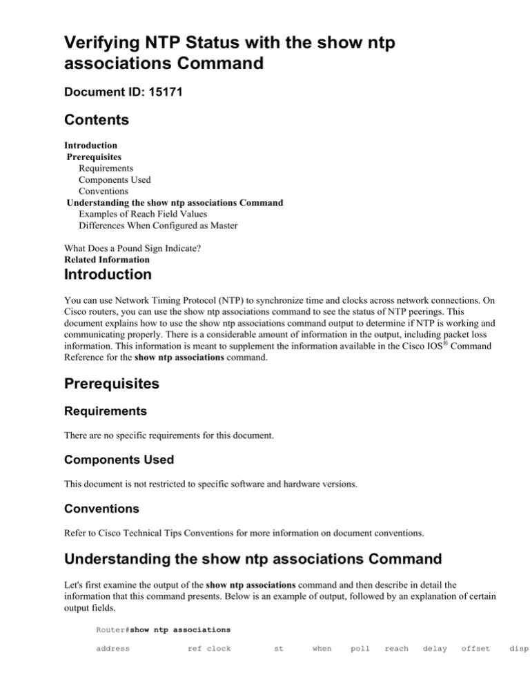
Let's first examine the output of the show ntp associations command and then describe in detail the
information that this command presents. Below is an example of output, followed by an explanation of certain
output fields.
Router#show ntp associations
address
ref clock
st
when
poll
reach
delay
offset
disp
~172.31.32.2
+~192.168.13.33
*~192.168.13.57
* master (synced),
172.31.32.1
5
29
1024
377
4.2
−8.59
192.168.1.111
3
69
128
377
4.1
3.48
192.168.1.111
3
32
128
377
7.9
11.18
# master (unsynced), + selected, − candidate, ~ configured
The poll field represents the polling interval (in seconds) between NTP poll packets. As the NTP server and
client are better synced and there aren't dropped packets, this number increases to a maximum of 1024. The
offset field is the calculated offset (in milliseconds) between the client and server time. The client slows down
or speeds up its clock to match the server's time value. The offset decreases toward zero over time. It probably
will never reach zero since the packet delay between the client and server is never exactly the same, so the
client NTP can't ever exactly match its clock with the server's. Additional details about the output field are
explained in the Basic System Management Commands document.
If there's an asterisk (*) next to a configured peer, then you are synced to this peer and using them as the
master clock. As long as one peer is the master then everything is fine. However, the key to knowing that NTP
is working properly is looking at the value in the reach field. Let's look at this field in more detail.
Examples of Reach Field Values
The reach field is a circular bit buffer. It gives you the status of the last eight NTP messages (eight bits in
octal is 377, so you want to see a reach field value of 377). If an NTP response packet is lost, the missing
packet is tracked over the next eight NTP update intervals in the reach field. The table below provides
explanations for possible reach field values using the loss of an NTP response packet as an example.
Reach Field Value
(Reported/Binary)
377 = 1 1 1 1 1 1 1 1
Explanation
Time 0: Last eight responses from
server were received
376 = 1 1 1 1 1 1 1 0
Time 1: Last NTP response was
NOT received (lost in network)
375 = 1 1 1 1 1 1 0 1
Time 2: Last NTP response was
received
373 = 1 1 1 1 1 0 1 1
Time 3: Last NTP response was
received
367 = 1 1 1 1 0 1 1 1
Time 4: Last NTP response was
received
357 = 1 1 1 0 1 1 1 1
Time 5: Last NTP response was
received
337 = 1 1 0 1 1 1 1 1
Time 6: Last NTP response was
received
277 = 1 0 1 1 1 1 1 1
Time 7: Last NTP response was
received
177 = 0 1 1 1 1 1 1 1
Time 8: Last NTP response was
received
377 = 1 1 1 1 1 1 1 1
Time 9: Last NTP response was
received
1.6
2.3
3.6
Differences When Configured as Master
When the router is using its own clock as a master clock (using the ntp master command), the output from
show ntp associations looks like the following:
address
ref clock
st
when
poll
reach
delay
offset
*~127.127.7.1
127.127.7.1
6
20
64
377
0.0
0.00
* master (synced), # master (unsynced), + selected, − candidate, ~ configured
disp
0.0
The interesting value here is in the stratum field, which is one less than the configured value, ntp master 7 in
this case. The router polls its own internal clock, but the clock is never unreachable, and the router never
increases the poll interval to more than every 64 seconds.
What Does a Pound Sign Indicate?
A pound sign (#) displayed next to a configured peer in the show ntp associations command output indicates
that the router isn't syncing with the peer even though NTP request and response packets are being exchanged.
In this case, check the output of the show ntp associations detail command or the NTP debugs to see why the
clocks aren't syncing. You can use the show ntp associations detail and show ntp status commands to obtain
additional information regarding the state of NTP.
One possible reason for the pound sign is that the NTP client's clock differs by more than 4000 seconds from
the NTP server's clock. On Cisco routers a time difference of greater than 4000 seconds is considered out of
range, and prevents the router from syncing to the server. This doesn't apply when you first configure an NTP
peer on a Cisco router or at a reload. In this case, the NTP client's (the Cisco router's) clock is changed to
match the NTP server's clock, no matter how large the difference.
Make sure you check the time zone of the client's clock; local time is displayed, but time values in NTP
messages are in UTC (GMT) time zone. You can manually change the client's clock to within a few minutes
of the NTP server's clock.
Related Information
• Network Time Protocol (NTP) Issues Troubleshooting and Debugging Guide
• Technical Support & Documentation − Cisco Systems
Contacts & Feedback | Help | Site Map
© 2014 − 2015 Cisco Systems, Inc. All rights reserved. Terms & Conditions | Privacy Statement | Cookie Policy | Trademarks of
Cisco Systems, Inc.
Updated: Mar 19, 2014
Document ID: 15171

