®
Altera Programming
Hardware
January 1998, ver. 4
General
Description
Data Sheet
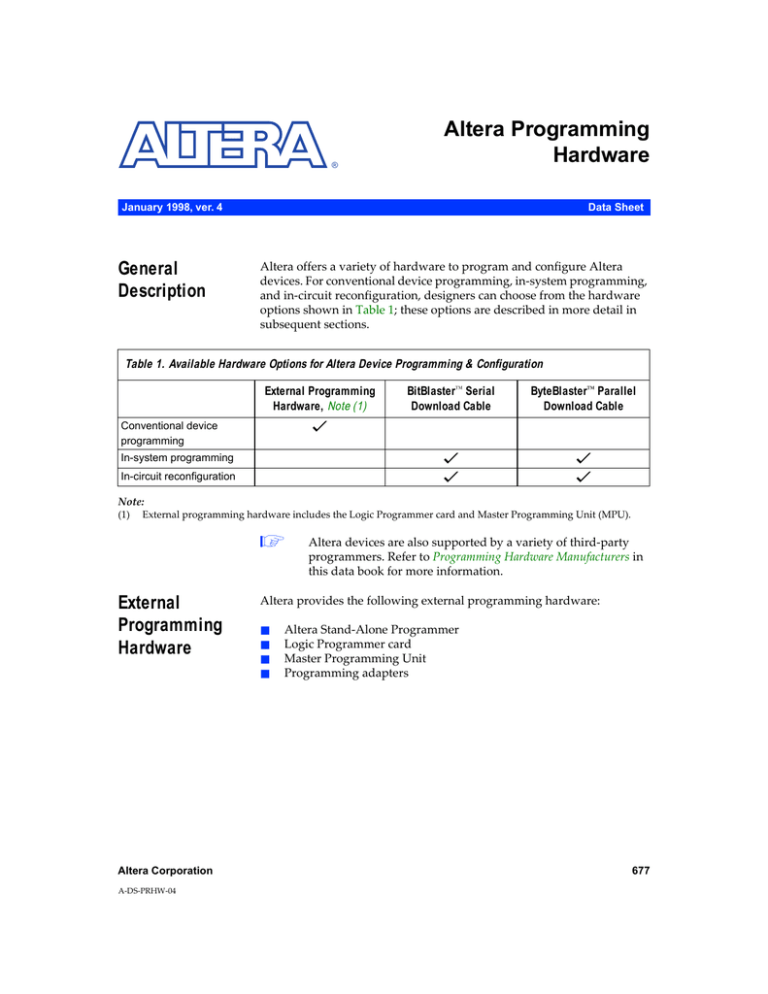
Altera offers a variety of hardware to program and configure Altera
devices. For conventional device programming, in-system programming,
and in-circuit reconfiguration, designers can choose from the hardware
options shown in Table 1; these options are described in more detail in
subsequent sections.
Table 1. Available Hardware Options for Altera Device Programming & Configuration
External Programming
Hardware, Note (1)
BitBlaster™ Serial
Download Cable
ByteBlaster™ Parallel
Download Cable
v
Conventional device
programming
In-system programming
v
v
In-circuit reconfiguration
v
v
Note:
(1)
External programming hardware includes the Logic Programmer card and Master Programming Unit (MPU).
1
External
Programming
Hardware
Altera Corporation
A-DS-PRHW-04
Altera devices are also supported by a variety of third-party
programmers. Refer to Programming Hardware Manufacturers in
this data book for more information.
Altera provides the following external programming hardware:
■
■
■
■
Altera Stand-Alone Programmer
Logic Programmer card
Master Programming Unit
Programming adapters
677
Altera Programming Hardware Data Sheet
Altera Stand-Alone Programmer
The Altera Stand-Alone Programmer (PL-ASAP2), together with the
appropriate programming adapters, provides the hardware and software
needed for programming EPROM- and EEPROM-based devices, and for
configuring SRAM-based devices. PL-ASAP2 includes an LP6 Logic
Programmer card, an MPU, MAX+PLUS® II Programmer software
(which requires Microsoft Windows 3.x, Windows 95, or Windows NT),
and complete documentation. The MAX+PLUS II Programmer supports
device configuration for FLEX® 10K, FLEX 8000, and FLEX 6000 devices,
and device programming for MAX® 9000, MAX 7000, MAX 5000,
Classic™, and Configuration EPROM devices.
Ordering Code:
PL-ASAP2
Logic Programmer Card
The LP6 Logic Programmer card generates programming waveforms and
voltages for the MPU. The software-controlled card can be installed into
any full-length computer expansion slot in an IBM PC or compatible
computer. The LP6 card is available as part of PL-ASAP2 or individually.
Ordering Code:
PLP6
Master Programming Unit
The MPU is a hardware module that is used together with an appropriate
adapter to program Altera devices. The MPU connects to a Logic
Programmer card via a 25-pin ribbon cable. The MPU receives power
from the Logic Programmer card and does not require an external power
supply. Programming and functional test information is transmitted from
the Logic Programmer card through the ribbon cable to the MPU. A
programming status light on the MPU lights up when the unit is active.
When used with the appropriate adapter, the MPU automatically tests for
continuity between the device leads and the programming socket before
programming. It can also apply test vectors to functionally test and verify
programmed Altera devices. Test vectors can be created in waveform or
text format in the MAX+PLUS II Waveform Editor or Text Editor and
applied to the device; results can be viewed in waveform or text format.
The MPU is available as part of the PL-ASAP2 or individually.
Ordering Code:
678
PL-MPU
Altera Corporation
Altera Programming Hardware Data Sheet
Programming Adapters
Altera provides three types of programming adapters for Altera devices:
PLM-prefix adapters, PLE-prefix adapters, and the PLAD3-12
compatibility adapter. Each adapter contains one of the following sockets:
a zero-insertion-force dual in-line package (DIP), plastic or ceramic J-lead
(PLCC/JLCC), pin-grid array (PGA), small-outline integrated circuit
(SOIC), or quad flat pack (QFP). Most adapters for QFP devices with 100
or more pins support Altera’s QFP carriers. Adapters with an “NC” suffix
program QFP devices that are not in a QFP carrier. Table 2 on page 680
lists the adapters required for each Altera device and package option.
f
See the QFP Carrier & Development Socket Data Sheet in this data book for
more information.
PLM-Prefix Adapters
The PLM-prefix adapters plug directly into the MPU. Each adapter
provides programming support for a specific device package.
Additionally, PLM-prefix adapters (except the PLMJ1213 and PLMT1064)
support functional testing of programmed Altera devices. The PLMJ1213
and PLMT1064 adapters can program the Configuration EPROMs used to
configure FLEX 10K, FLEX 8000, and FLEX 6000 devices.
PLE-Prefix Adapters
The PLE-prefix adapters plug into the PLAD3-12 compatibility adapter,
which in turn plugs into the MPU. Each PLE-prefix adapter provides
programming support for a specific Classic device.
PLAD3-12 Compatibility Adapter
The PLAD3-12 compatibility adapter plugs directly into the MPU. This
adapter allows PLE-prefix adapters to be used with the MPU. See Table 2.
Altera Corporation
679
Altera Programming Hardware Data Sheet
Table 2. Programming Adapters & Hardware Support (Part 1 of 3)
Device
Package
BitBlaster &
ByteBlaster
Support
FLEX 10K
All packages
Note (2)
v
FLEX 8000
All packages
Note (2)
v
FLEX 6000
All packages
Note (2)
v
EPC1
DIP
J-Lead
PLMJ1213
PLMJ1213
–
EPC1441
DIP
J-lead
TQFP
PLMJ1213
PLMJ1213
PLMT1064
–
EPC1213
DIP
J-lead
PLMJ1213
PLMJ1213
–
EPC1064
EPC1064V
DIP
J-lead
TQFP
PLMJ1213
PLMJ1213
PLMT1064
–
EPM9320
EPM9320A
J-lead (84-pin)
RQFP (208-pin)
PLMJ9320-84
PLMR9000-208
PLMR9000-208NC
PLMR9000-280
v
PLMJ9400-84
PLMR9000-208
PLMR9000-208NC
PLMR9000-240
PLMR9000-240NC
v
PLMR9000-208
PLMR9000-208NC
PLMR9000-240
PLMR9000-240NC
v
v
PGA (280-pin)
RQFP (304-pin)
BGA (356-pin)
PLMR9000-208
PLMR9000-208NC
PLMR9000-240
PLMR9000-240NC
PLMG9000-280
PLMR9000-304
Note (3)
J-lead
PQFP
TQFP
PLMJ7000-44
PLMQ7000-44
PLMT7000-44
RQFP (240-pin)
EPM9400
EPM9400A
J-lead (84-pin)
RQFP (208-pin)
RQFP (240-pin)
EPM9480
EPM9480A
RQFP (208-pin)
RQFP (240-pin)
EPM9560
EPM9560A
RQFP (208-pin)
RQFP (240-pin)
EPM7032
EPM7032V
EPM7032S
EPM7032A
680
Adapter
Note (1)
v(4)
Altera Corporation
Altera Programming Hardware Data Sheet
Table 2. Programming Adapters & Hardware Support (Part 2 of 3)
Device
EPM7064
EPM7064S
EPM7064A
Package
J-lead (44-pin)
TQFP (44-pin)
J-lead (68-pin)
J-lead (84-pin)
PQFP (100-pin)
BitBlaster &
ByteBlaster
Support
v(4)
TQFP (100-pin)
PLMJ7000-44
PLMT7000-44
PLMJ7000-68
PLMJ7000-84
PLMQ7000-100
PLMQ7000-100NC
PLMT7000-100NC
EPM7096
J-lead (68-pin)
J-lead (84-pin)
PQFP (100-pin)
PLMJ7000-68
PLMJ7000-84
PLMQ7000-100
EPM7128E
EPM7128S
EPM7128A
J-lead (84-pin)
PQFP (100-pin)
PLMJ7000-84
PLMQ7000-100
PLMQ7000-100NC
PLMQ7128/7160-160
PLMQ7128/160-160NC
Note (3)
v(4)
PQFP (160-pin)
TQFP (144-pin)
–
EPM7160E
EPM7160S
J-lead (84-pin)
TQFP (100-pin)
PQFP (100-pin)
PQFP (160-pin)
PLMJ7000-84
PLMT7000-100NC
PLMQ7000-100
PLMQ7128/7160-160
PLMQ7128/160-160NC
PLMT7000-100NC
v(4)
EPM7192E
EPM7192S
PGA (160-pin)
PQFP (160-pin)
PLMG7192-160
PLMQ7192/7256-160
PLMQ7192/256-160NC
v(4)
EPM7256E
EPM7256S
EPM7256A
PGA (192-pin)
PQFP (160-pin)
PLMG7256-192
PLMQ7192/7256-160
PLMQ7192/256-160NC
PLMR7256-208
PLMR7256-208NC
Note (3)
v(4)
RQFP (208-pin)
PQFP (208-pin)
TQFP (144-pin)
Altera Corporation
Adapter
Note (1)
EPM7384A
TQFP (144-pin)
PQFP (208-pin)
BGA (256-pin)
Note (3)
v
EPM7512A
TQFP (144-pin)
PQFP (208-pin)
BGA (256-pin)
Note (3)
v
EPM71024A
PQFP (208-pin)
BGA (256-pin)
Note (3)
v
681
Altera Programming Hardware Data Sheet
Table 2. Programming Adapters & Hardware Support (Part 3 of 3)
Device
Package
Adapter
Note (1)
BitBlaster &
ByteBlaster
Support
EPM5032
DIP
J-lead
PLMD5032A
PLMJ5032A
–
EPM5064
J-lead
PLMJ5064A
–
EPM5128
EPM5128A
J-lead
PGA
PLMJ5128A
PLMG5128A
–
EPM5130
J-lead
PGA
PQFP
PLMJ5130A
PLMG5130A
PLMQ5130A
–
EPM5192
J-lead
PGA
PLMJ5192A
PLMG5192A
–
EP600
EP610
DIP
J-lead
SOIC
PLED610
PLEJ610
PLES610
–
EP900
EP910
DIP
J-lead
PLED910
PLEJ910
–
EP1810
J-lead
PGA
PLMJ1810
PLEG1810
–
Notes:
(1)
(2)
(3)
(4)
Adapters with an NC suffix program QFP devices that are not in QFP carriers.
Configuration of FLEX 10K, FLEX 8000, or FLEX 6000 devices is supported by
Configuration EPROMs (EPC1064, EPC1064V, EPC1213, EPC1441, and EPC1), and
the BitBlaster or ByteBlaster download cable.
A BitBlaster or ByteBlaster download cable is used to program this device via insystem programming.
The BitBlaster and ByteBlaster download cables support in-system programming
of MAX 7000S and MAX 7000A devices.
Ordering Codes:
BitBlaster
Serial
Download
Cable
682
PLExxxx, PLMxxxx, PLAD3-12
The BitBlaster serial download cable is a hardware interface to a standard
PC or UNIX workstation RS-232 port (known as a “COM port” on a PC
and a “ttya port” or “ttyb port” on a UNIX workstation) that provides
configuration data to FLEX 10K, FLEX 8000, and FLEX 6000 devices and
programming data to MAX 9000, MAX 7000S, and MAX 7000A devices.
Altera Corporation
Altera Programming Hardware Data Sheet
The 25-pin female port on the BitBlaster download cable connects to
an RS-232 port with a standard serial cable. The 10-pin female plug
on the BitBlaster download cable connects to a device on a circuit
board via a 10-pin male header. The BitBlaster cable contains status
lights that indicate the state of the device configuration or
programming. Refer to the BitBlaster Serial Download Cable Data Sheet
in this data book for more information.
Ordering Code:
1
ByteBlaster
Parallel
Download Cable
PL-BITBLASTER
To configure/program 3.3-V devices (e.g., FLEX 10KA and
MAX 7000A devices), using a BitBlaster download cable,
connect the cable’s VCC pin to a 5.0-V power supply and the
device to a 3.3-V power supply. FLEX 10KA and
MAX 7000A devices have 5.0-V tolerant inputs, so the
download cable’s 5.0-V output will not harm these 3.3-V
devices. The pull-up resistors should be connected to the
5.0-V power supply.
The ByteBlaster parallel download cable is a hardware interface to a
standard parallel port (also known as an LPT port). This cable
channels configuration data to FLEX 10K, FLEX 8000, and FLEX 6000
devices as well as programming data to MAX 9000, MAX 7000S, and
MAX 7000A devices.
The ByteBlaster download cable has a 25-pin male header that
connects to the PC parallel port, and a 10-pin female plug that
connects to the circuit board. Data is downloaded from the PC’s
parallel port through the ByteBlaster to the circuit board. The
ByteBlaster 10-pin plug is identical to the BitBlaster 10-pin plug.
Refer to the ByteBlaster Parallel Port Download Cable Data Sheet in this
data book for more information.
Ordering Code:
1
Altera Corporation
PL-BYTEBLASTER
To configure/program 3.3-V devices (e.g., FLEX 10KA and
MAX 7000A devices), using a ByteBlaster download cable,
connect the cable’s VCC pin to a 5.0-V power supply and the
device to a 3.3-V power supply. FLEX 10KA and
MAX 7000A devices have 5.0-V tolerant inputs, so the
download cable’s 5.0-V output will not harm these 3.3-V
devices. The pull-up resistors should be connected to the
5.0-V power supply.
683
Altera Programming Hardware Data Sheet
Programming
Techniques
Table 3 summarizes programming/configuration techniques.
Table 3. Programming/Configuration Techniques by Device Family
Device Family
FLEX 10K, Note (1)
Programming/Configuration Techniques
Download configuration data via the BitBlaster or ByteBlaster download cables, or
an embedded microprocessor using the JTAG ports.
FLEX 10K, FLEX 8000, or In passive serial (PS) mode, download configuration data via the BitBlaster or
FLEX 6000
ByteBlaster download cables.
Configure devices via an on-board microcontroller.
FLEX 10K and FLEX 6000 Configure devices via an EPC1 or EPC1441 Configuration EPROM.
FLEX 8000
Configure devices via an EPC1, EPC1441, EPC1213, EPC1064, or EPC1064V
Configuration EPROM.
Program devices in-system via the BitBlaster or ByteBlaster and the JTAG ports.
MAX 9000, MAX 7000S,
and MAX 7000A, Note (1) Program devices via the MPU and the LP6 card and the appropriate adapters.
Program devices via third-party programming hardware.
Program devices in-system via in-circuit test (ICT) equipment or an on-board
microcontroller.
MAX 7000
MAX 5000
Classic
Program using the MPU and the LP6 card and the appropriate adapters.
Program using third-party programming hardware.
Note:
(1)
684
To configure or program 3.3-V devices (e.g., FLEX 10KA and MAX 7000A devices) using a BitBlaster or ByteBlaster
download cable, connect the cable’s VCC pin to a 5.0-V power supply and the device to a 3.3-V power supply.
FLEX 10KA and MAX 7000A devices have 5.0-V tolerant inputs, so the download cable’s 5.0-V output will not harm
these 3.0-V devices. The pull-up resistors should be connected to the 5.0-V power supply.
Altera Corporation
Copyright © 1995, 1996, 1997, 1998 Altera Corporation, 101 Innovation Drive,
San Jose, CA 95134, USA, all rights reserved.
By accessing this information, you agree to be bound by the terms of Altera’s
Legal Notice.


