Historical Development of the Shack-Hartmann Wavefront Sensor
advertisement

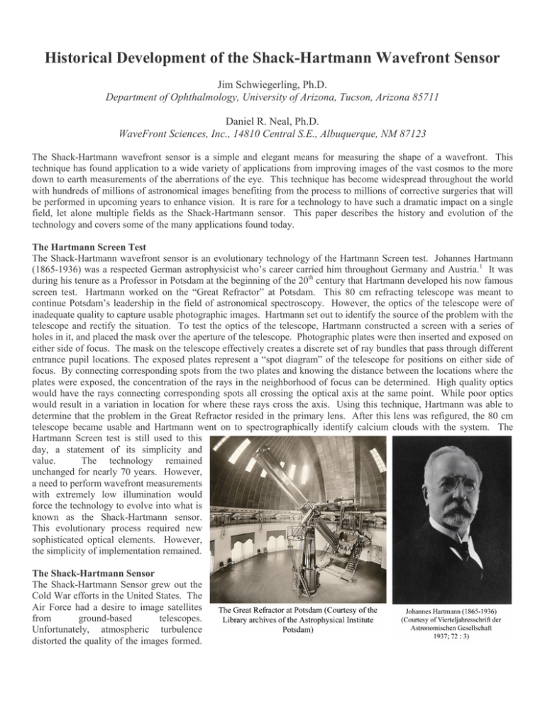
Historical Development of the Shack-Hartmann Wavefront Sensor Jim Schwiegerling, Ph.D. Department of Ophthalmology, University of Arizona, Tucson, Arizona 85711 Daniel R. Neal, Ph.D. WaveFront Sciences, Inc., 14810 Central S.E., Albuquerque, NM 87123 The Shack-Hartmann wavefront sensor is a simple and elegant means for measuring the shape of a wavefront. This technique has found application to a wide variety of applications from improving images of the vast cosmos to the more down to earth measurements of the aberrations of the eye. This technique has become widespread throughout the world with hundreds of millions of astronomical images benefiting from the process to millions of corrective surgeries that will be performed in upcoming years to enhance vision. It is rare for a technology to have such a dramatic impact on a single field, let alone multiple fields as the Shack-Hartmann sensor. This paper describes the history and evolution of the technology and covers some of the many applications found today. The Hartmann Screen Test The Shack-Hartmann wavefront sensor is an evolutionary technology of the Hartmann Screen test. Johannes Hartmann (1865-1936) was a respected German astrophysicist who’s career carried him throughout Germany and Austria.1 It was during his tenure as a Professor in Potsdam at the beginning of the 20th century that Hartmann developed his now famous screen test. Hartmann worked on the “Great Refractor” at Potsdam. This 80 cm refracting telescope was meant to continue Potsdam’s leadership in the field of astronomical spectroscopy. However, the optics of the telescope were of inadequate quality to capture usable photographic images. Hartmann set out to identify the source of the problem with the telescope and rectify the situation. To test the optics of the telescope, Hartmann constructed a screen with a series of holes in it, and placed the mask over the aperture of the telescope. Photographic plates were then inserted and exposed on either side of focus. The mask on the telescope effectively creates a discrete set of ray bundles that pass through different entrance pupil locations. The exposed plates represent a “spot diagram” of the telescope for positions on either side of focus. By connecting corresponding spots from the two plates and knowing the distance between the locations where the plates were exposed, the concentration of the rays in the neighborhood of focus can be determined. High quality optics would have the rays connecting corresponding spots all crossing the optical axis at the same point. While poor optics would result in a variation in location for where these rays cross the axis. Using this technique, Hartmann was able to determine that the problem in the Great Refractor resided in the primary lens. After this lens was refigured, the 80 cm telescope became usable and Hartmann went on to spectrographically identify calcium clouds with the system. The Hartmann Screen test is still used to this day, a statement of its simplicity and value. The technology remained unchanged for nearly 70 years. However, a need to perform wavefront measurements with extremely low illumination would force the technology to evolve into what is known as the Shack-Hartmann sensor. This evolutionary process required new sophisticated optical elements. However, the simplicity of implementation remained. The Shack-Hartmann Sensor The Shack-Hartmann Sensor grew out the Cold War efforts in the United States. The Air Force had a desire to image satellites from ground-based telescopes. Unfortunately, atmospheric turbulence distorted the quality of the images formed. The military approached Aden Meinel and the Optical Sciences Center (OSC) at the University of Arizona to undertake a project that would resolve the imaging problem. It was Meinel who first suggested tapping into the incident light and using a Hartmann test to determine atmospheric aberrations at the time the image of the satellite was captured. Armed with the knowledge of these aberrations, the resulting image could be processed to improve its quality. Roland Shack, who Meinel had recruited to OSC several years earlier, was given the task of determining if this technique was feasible. Several severe limitations of the Hartmann technique became immediately obvious. Satellites themselves send little light to the ground-based telescopes. Most of this light is needed to record the image of the satellite, so only a small fraction of the available light can be sent to the Hartmann screen. The Hartmann Screen furthermore dramatically reduces the amount of light since it blocks all but the photons passing through its holes. Shack’s first innovation was to place lenses within each of the holes in the Hartmann Screen. By adding lenses, the light passing through the apertures would be concentrated to a focal spot. This concentration would aid in boosting the photon density and allowing the spot to be recorded. Shack’s second insight was that the screen itself was no longer needed. If the diameters of the lenses expanded until their edges met, then all of the photons incident on the screen would find their way to a focal spot. Consequently, this setup creates the most efficient use of the incident light possible, an ideal situation for a system that suffers from too few photons. The next step in the implementation of the technique was to obtain a suitable array of lenses Lenslet Array Fabrication The concept of the lenslet array was not new and arrays were commercially available. Some high-speed photography systems utilized lenslet arrays to capture images in low-lighting conditions at the expense of resolution. However, the dimensions and focal lengths of the commercially available lenslets were not appropriate for the satellite-imaging problem, and manufacturers wanted immoderate fees to fabrication a suitable array. Fabrication of the lenslet arrays for this project needed to be performed within OSC. Ben Platt, a graduate student at OSC, was assigned to Shack to work on the development of the lenslet arrays. After multiple failed attempts, they devised a scheme for fabricating the lenslet arrays.2 The fabrication technique involved grinding and polishing a series of concave cylindrical grooves into glass plates. A nylon rod of roughly 120 mm in diameters was mounted on a steel rod so that the nylon rod could be slid back and forth along the steel rod. A glass plate was placed under the nylon rod with some polishing compound. Repeatedly, stroking the nylon rod over the glass plate created a polished cylindrical groove in the glass plate. Once the groove reached a width of 1 mm, the nylon rod was lifted, the glass plate translated by 1 mm and the polishing process repeated. In this manner, an array of concave grooves was formed in the glass. The glass array was then split into two pieces and used as master mold lenslet arrays. One-millimeter thick thermal plastic (Plexiglass) was molded between the two orthogonally oriented pieces of the glass master. The molded part consequently had an array of cylinder lenses along one side and a second array cylinder lenses rotated by 90 degrees on its other side. For the 1 mm aperture of the lenslets, the combined cylindrical lenses are indistinguishable from a spherical lens. With the lenslets in hand, the wavefront sensor was complete and delivered to the Air Force satellite-tracking telescope in Cloudcroft, New Mexico. Unfortunately, the system was never used, and it is unknown what became of this original wavefront sensor. High Energy Laser Applications The application of the Shack-Hartmann technique diverges somewhat from the point in the early 1970s when OSC delivered the original system to the Air Force. The Department of Defense certainly had interest in being able to measure wavefront aberrations. High-energy gas dynamic and chemical lasers had been developed at this time under classified programs. At such high energies, mirrors would distort under the heat loads. Adaptive correction of the mirrors was needed to correct these distortions and, consequently, wavefront sensors were needed to measure the wavefront distortions. Much of the work that went on during the 1970s and 1980s was, or is, classified, so it is difficult to relay much of this history. Ben Platt, the student who originally fabricated the lenslet arrays, worked within this community. Dale Neal, the father of one of the authors (DN) was also the program manager for several of these projects. Dale Neal notes: “As early as 1972 both the Air Force and Navy had gotten at least 100 kw out of Gas Dynamic and Chemical lasers respectively (built by Pratt and Whitney and TRW} in a CW mode. By 1980 the GD laser had produced about 350 kw and the chemical laser over 1 MW. At the time these numbers were classified. The DoD recognized early on (by at least 1972) that they had problems with mirror distortion under heat loads from the lase, and that they needed adaptive optics. In fact, I think the term "adaptive optics" was coined by someone in the DOD community. Leaders in this area at the time were Itek, Hughes, Perkin-Elmer and United Technologies Research Center. Itek and Perkin Elmer built some of the early wavefront sensors, mostly shearing interferometers back in the 74-76 era. Julius Feinleib, then at Itek but later at AOA, built one of the first Shack-Hartmann sensors sometime about 1977. Hughes and UTRC built the first deformable mirrors (cooled) for the AFWL and the Navy. PE later built a modal DM for AFWL around 1976.” “The AFWL itself had several key engineers and scientists doing research and development on AO, including Ben Platt, who then worked for UDRI. For over 20 years starting in around 1970, a lot of work went on in-house on wavefront sensors, DMs and control system techniques. Thermal blooming was recognized as a problem in the atmosphere around 1975, and a lot of work was done to solve that problem, including the low speed wind tunnel that I managed (but Jim Harvey and Bruce Pierce built). In the 80's, a lot of the emphasis shifted to the Space Based Laser, which did not have the thermal blooming problem but still had mirrors that distorted under heat load.” In the late 1970s and throughout the 1980s, there were numerous developments for the high-energy laser community in Shack-Hartmann wavefront sensing and adaptive optics. While these are mostly classified, there is some published work that describes the development.11,12,16 Dan Neal also has an extensive history of utilizing this technology for high-energy laser applications and has commercialized the technology into WaveFront Sciences. More about his history and the evolution of the commercialized technology can be found in his article Shack- Hartmann sensor engineered for commercial measurement applications contained in this volume. Astronomy Applications In parallel with the Department of Defense, the civilian astronomy community slowly latched onto the potential of the Shack-Hartmann technique. The University of Arizona is located in the heart of American astronomy community. Interest in Shack’s technology failed to appear from this group though. In the early to mid 1970s, Shack handed out lenslet arrays to visiting astronomy researchers, but the value of his work was not realized until Ray Wilson from the European Southern Observatory visited OSC in 1976.3 Wilson first conceived active optics correction of astronomy telescopes in 1968.4 His concept was that if the amount and directions of the various aberrations associated with the large mirrors could be measured, then they could be actively compensated. What was lacking at this point however was a wavefront measuring that could quickly perform the analysis. The classical Hartmann test was too slow to allow active correction. Following a second visit to OSC in 1977, Wilson returned with one of the original lenslet arrays and used it to demonstrate active optical correction of a 1 m mirror. The other key technology that made the active system feasible was the advent of the CCD camera. The ShackHartmann wavefront sensor provided precise measurement of the mirror aberrations and the CCD camera allowed for rapid capture and analysis of the resulting spot patterns. Significant development in satellite imaging was eventually unclassified to allow application to the astronomical community.13-15 Even with the concept demonstrated, the ShackHartmann technique was not implemented on a telescope until the 1980s. The ESO 3.6 m telescope saw first light in March of 1989 and represented the first actively corrected astronomical telescope. The processed images from this telescope illustrated details well beyond that of the undercorrected images. Following this real demonstration, the astronomers from around the world became highly interested in the technique, and while several other wavefront measuring techniques have been implemented for correcting astronomical telescopes, the Shack-Hartmann technique is by far the most actively used technology today. Ophthalmic Applications In the mid-1980s, Shack visited Josef Bille at the University of Heidelberg. Bille was the first to apply the Shack-Hartmann technique to the eye. The technique was first applied to measuring corneal topography5 and later to measuring the aberrations of the entire eye.6-7 This initial work by Bille and his students has enabled the modern treatment of refractive error and the enhanced visualization of the structure of the retina. The advent of the excimer laser has enabled precise sculpting of the cornea. By reshaping the curvature of the cornea, myopia, hyperopia and astigmatism can be corrected. Millions of people have been treated with this technology to dramatically reduce their defocus and astigmatism. Correction of individual aberrations is a natural endpoint for this technology and the Shack-Hartmann technique has played a pivotal role in enabling the customization of refractive surgery. As with astronomy, other wavefront measuring techniques have been implemented, but yet again the Shack-Hartmann sensor is the most widespread and well known technology for performing customized correction. By treating aberrations in the eye, the normal 20/20 acuity is often improved upon, and even the poor outcomes are nearly always achieving “normal” 20/20 vision. While the Shack-Hartmann sensor connected to a refractive surgery laser has enabled a better look out of the eye, the wavefront sensor connected to an adaptive optics mirror and a fundus camera has enabled a better look into the eye. Armed with this technology, ophthalmologists and vision scientists may be able to provide better treatment for retinal disease and a better understanding of the underlying structure of the retina. Researchers from the University of Rochester have been largely responsible for first demonstrating the techniques and performing some of the most advanced research in retinal imaging.8-9 They were the first group to be able to resolve individual photoreceptors in vivo. The aberrations of the eye are sufficiently large to prevent imaging of the cones without this type of adaptive correction. While commercial Shack-Hartmann systems are available for refractive surgery10, the application of the Shack-Hartmann technique and adaptive optics to ophthalmic applications is just beginning to mature. Commercial versions of adaptive-optics-based fundus cameras, phoropters and scanning laser ophthalmoscopes will soon appear. Summary In researching the history of the Shack-Hartmann wavefront sensor, Ray Wilson provided a wonderful quote from Roland Shack: “It is very strange that everyone is satisfied with my work, except for me.” This dissatisfaction illustrates a desire to strive beyond the status quo and achieve one’s full potential. It is the results of these efforts that have led to a simple and elegant technology that has advanced our knowledge of the universe and has enhanced our perception of the world. It is rare for technologies to have such a broad impact in multiple disciplines. We applaud Roland’s work and the benefits it has provided to all. References 1. Labitzke P. Neue Deutsche Biografie, 1966; 7:744-45. 2. Platt BC, Shack R. History and principles of Shack-Hartmann wavefront sensing, J Refract Surg 2001; 17:S573-S577. 3. Wilson RN. Addendum to the history and development of the ESO active optics system. ESO Messenger 2003; 114:9. 4. Wilson RN. The history and development of the ESO active optics system. ESO Messenger 2003; 113:2-9. 5. Goelz S, Persoff JJ, Bittner GD, Liang J, Hsueh CT, Bille JF. A new wavefront sensor for metrology of spherical surfaces. SPIE 1991; 1542:502-511. 6. Liang J. A new method to precisely measure the wave aberrations of the human eye with a Hartmann-ShackWavefront-Sensor. PhD dissertation, University of Heidelberg (1991). 7. Liang J, Grimm B, Goelz S, Bille JF. Objective measurement of wave aberrations of the human eye with the use of a Hartmann-Shack wave-front sensor. J Opt Soc Am A 1994; 11:1949-1957. 8. Liang J, Williams DR, Miller DT. Supernormal vision and high-resolution retinal imaging through adaptive optics. J Opt Soc Am A 1997; 14: 2884-2892. 9. Roorda A, Williams DR. The arrangement of the three cone classes in the living human eye. Nature 1999; 397: 520522. 10. Krueger, Applegate, and MacRae, Wavefront customized visual correction: the quest for super vision II, Slack Inc, 2004. 11. A J. W. Hardy, “Adaptive optics-a progress review,” SPIE 1542, pp. 2-17 (1991). 12. B D. Greenwood and C. A. Primmerman, “The history of adaptive-optics development and the MIT Lincoln Laboratory,” SPIE 1920, pp. 220 – 234 (1993). 13. R. Q. Fugate, “Measurement of atmospheric distortion using scattered light from a laser guidestar,” Nature 353, pp. 144-146 (Sept 12, 1991). 14. R. Q. Fugate, et al, “Two generations of laser-guide-star adaptive optics experiments at the Starfire Optical Range,” JOSA A, 11(1), pp. 310-324 (1994). 15. R. Q. Fugate, “Observations of faint objects with laser beacon adaptive optics,” SPIE 2201, pp. 10 – 21 (1994). 16. B. A. Horwitz, “Comparison approach for wavefront sensors,” SPIE 1920, pp. 186 – 192 (1993).


