ME 5550 Intermediate Dynamics Bearing Loads on a Simple Crank Shaft
advertisement
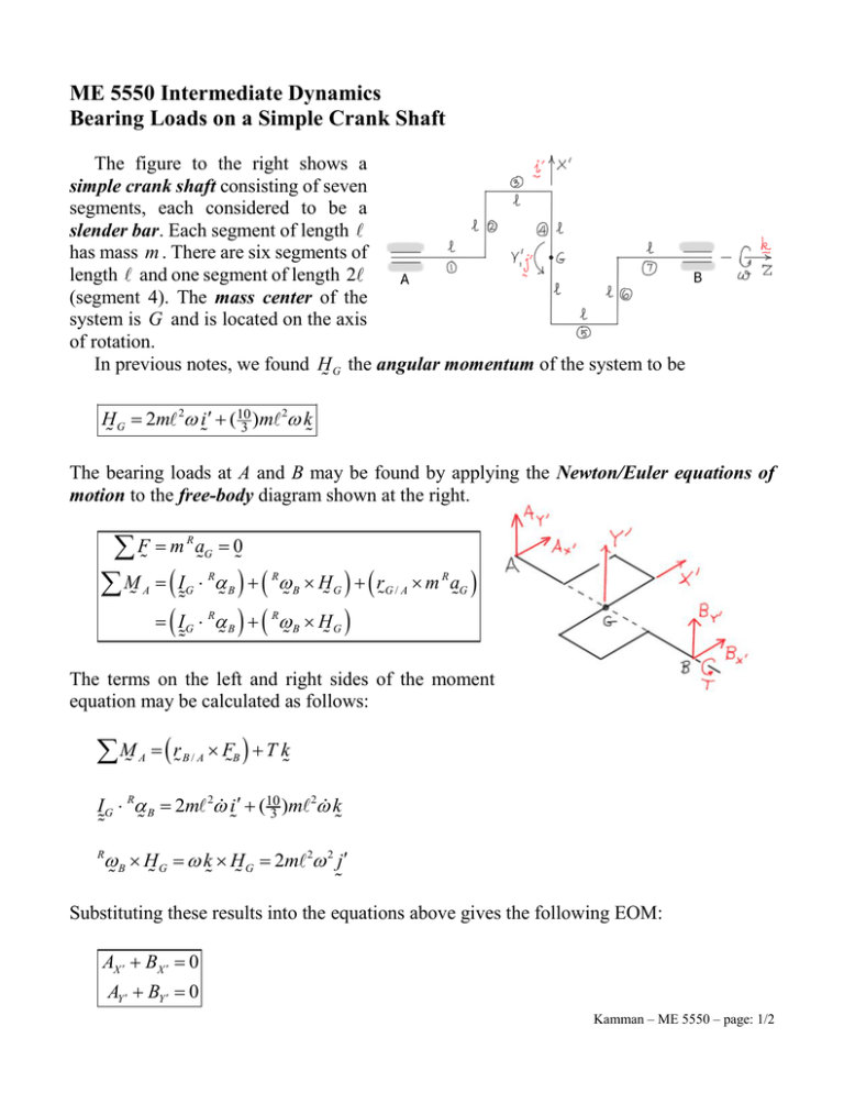
ME 5550 Intermediate Dynamics Bearing Loads on a Simple Crank Shaft The figure to the right shows a simple crank shaft consisting of seven segments, each considered to be a slender bar. Each segment of length has mass m . There are six segments of length and one segment of length 2 (segment 4). The mass center of the system is G and is located on the axis of rotation. In previous notes, we found H G the angular momentum of the system to be 2 H G 2m 2 i (10 3 )m k The bearing loads at A and B may be found by applying the Newton/Euler equations of motion to the free-body diagram shown at the right. F m M I A R G aG 0 R B R B H G r G / A m R aG I G R B B HG R The terms on the left and right sides of the moment equation may be calculated as follows: M A r B / A FB T k 2 IG R B 2m 2 i (10 3 )m k B HG k H G 2m 2 2 j R Substituting these results into the equations above gives the following EOM: AX BX 0 AY BY 0 Kamman – ME 5550 – page: 1/2 4 BY 2m 2 4 BX 2m 2 2 T 103 m 2 Solving these equations gives the following results BX 12 m 2 AX BY 12 m AY T 103 m 2 Kamman – ME 5550 – page: 2/2
