MODELING THE SYSTEM IMPACT OF COOLING PERFORMANCE ON A
advertisement

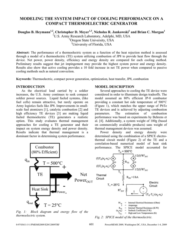
MODELING THE SYSTEM IMPACT OF COOLING PERFORMANCE ON A COMPACT THERMOELECTRIC GENERATOR Douglas B. Heymann1,2, Christopher D. Meyer1,3, Nicholas R. Jankowski1 and Brian C. Morgan1 1 U.S. Army Research Laboratory, Adelphi, MD, USA 2 Oregon State University, USA 3 University of Florida, USA Abstract: The performance of a thermoelectric system as a function of the heat rejection method is assessed through a model of a thermoelectric (TE) system utilizing combustion of JP8 to provide heat flow through the device. Net power, power density, efficiency and energy density are compared for each cooling method. Preliminary results suggest that jet impingement may provide the highest system power and energy density. Results also show that active cooling provides a 10 fold increase in net TE power when compared to passive cooling methods such as natural convection. Keywords: Thermoelectric, compact power generation, optimization, heat transfer, JP8, combustion INTRODUCTION MODEL DESCRIPTION As the electrical load carried by a soldier increases, the U.S. Army continues to seek compact soldier power sources. Liquid fueled systems, (like fuel cells) remain attractive, but rarely operate on Army logistics fuels like JP8. Improvements in smallscale fuel atomizers [1], catalytic combustion [2] and high efficiency TE devices [3] are making liquid fueled thermoelectric (TE) generators a realistic option. This study evaluates thermal management approaches for cooling a TE generator and their impact on system energy density and power density. Results indicate that thermal management is a dominant factor in determining system performance. Several approaches to cooling the TE device were considered in order to illuminate design tradeoffs. The model assumed an 80% efficient JP-8 combustor providing a constant hot side temperature of 500°C (Figure 1), which matches the upper range of PbTe TE devices and is achieved by adjusting combustion parameters. The estimation of combustion performance was based on experiments by Behrens et al. [4]. Additionally, a system weight of 100g (based on commercially available products) sans weight of thermal management devices was assumed. Power density and energy density were determined using the combination of a SPICE electrothermal circuit model (Figure 2) of the TE and a correlation-based numerical model of heat sink performance. The SPICE model accounted for Fig. 1: Block diagram and energy flow of the thermoelectric system. 0-9743611-5-1/PMEMS2009/$20©2009TRF Fig. 2: SPICE model of the thermoelectric. 601 PowerMEMS 2009, Washington DC, USA, December 1-4, 2009 for a volume of fluid per unit time (Q) to overcome a pressure difference (ΔP), taking into account an assumed fan efficiency (ε) of 25%. ℘ = ΔPQ ε (2) The net power is defined as the power output from the TE (PTE) minus the pumping power requirements. The power density is the net power divided by the mass of the device. The system efficiency (η) is defined as: η= Fig. 3: Illustration of TE power output as a function of cold side heat transfer coefficient for ZT=1.0. 1 1 hL = 0.664 Re 2 Pr 3 kf (3) Where Qin is the heat input into the thermoelectric. The energy density (e) is defined as: conductive heat flow through the device and power transfer between thermal and electrical domains. Material properties used in the model were gathered from present-day bulk PbTe materials having a figure of merit ZT=0.5 [5], with simulations for ZT=1.0 included to show potential improvements from new materials. A detailed definition of ZT is found in [5]. The SPICE results were used in the numerical heat sink algorithms to ascertain TE power as a function of cold side thermal resistance. The SPICE results are best visualized through Figure 3. This figure shows the power output possible from the system illustrated in Figure 2. Benefits in net power output are realized from heat transfer coefficients greater than 100 W/m2-K. These heat transfer coefficients are possible with airflow through characteristic dimensions less than 1mm. This yields a low thermal resistance, given that thermal resistance is the inverse of the product of convective surface are and heat transfer coefficient. The cold side heat transfer coefficient was calculated from the appropriate Nusselt number correlation [6, 7], and cooling method cost was determined from the additional mass and pumping/fan power. The Nusselt number (Nu) is the ratio of convective to conductive heat transfer coefficient for a particular configuration; a particular example of a correlation which involves the ratio of inertial to viscous forces (Re) of the flow and the ratio of viscous to thermal diffusion (Pr) of the fluid is: Nu = PTE −℘ Qin e= (PTE −℘)Δt (m sys + m& fuel Δt ) (3) Where Δt is the length of the mission, msys is the mass & fuel is the mass flow rate of the of the system and m fuel. The net power, power density and efficiency are presented as functions of fan power (Figures 4, 5 & 6) for each cooling design. Each design was selected to contrast the differences in power and weight penalties versus power output. The designs include naturally convected pin fins and geometry optimized jet impingement and forced convection over pin fins (all utilizing air as the working fluid). The following describes each cooling method. Pin Fins, Natural Convection The thermal resistance of approximately 5.0 K/W was used for a flared pin-fin heat sink from Cool Innovations (model no. 3-202010G). The heat sink adds a weight of approximately 60 g to the system. There are no additional pumping requirements. Jet Impingement A flat plate is used as a heat transfer surface but instead of flow parallel to the plate, nozzles direct airflow orthogonally to the plate’s surface. The resulting flow creates a relatively higher convection coefficient [6]. It is assumed that the jets are machined out of a light material, thus keeping the weight low in comparison to a convectional pin or finned heat sink. In the design of the subsequent heat sinks, a characteristic dimension is varied to illustrate its effects on net power/energy density and pumping (1) The pumping power (℘, Watts) is the power needed 602 Figure 4 illustrates the predicted net power from the thermoelectric system as a function of pumping power for all designs considered. Net power is the power output of the thermoelectric minus the power to pump air through the heat sink (i.e. pumping power), accounting for fan efficiency. Note in Figures 4 – 7 that a maximum exists, which marks the point where the most power is generated. At higher pumping powers, the energy cost does not justify the gain in TE power. The energy cost eventually exceeds TE power at which point net power becomes negative. When comparing the pin fins with jet impingement, one would expect that the increase in surface area would make the pin fin thermal resistance lower than that of jet impingement. However, Figure 4 shows that jet impingement results in lower thermal resistance because of a large heat transfer coefficient. The enhanced heat transfer coefficient results from large temperature gradients associated with the development zone around the jet’s impingement area, a more detailed explanation is provided in [6]. While net system power is a useful metric for evaluating the performance of a design, it fails to quantify the weight of the device. Power density is defined as the net power of the system divided by the weight of the system. This elucidates the weight penalty which aids in qualifying a system for portable or uncrewed air vehicle applications. Figure 5 illustrates the net system power density as a function of pumping power for each design. The jet impingement design increases its performance difference with the pin fin design (when compared with Figure 4) by approximately 14% because of the lack of added weight from a heat sink. Conversely, the difference in performance between the jet impingement and pin fin designs becomes less when system efficiency is analyzed. This is evident in Figure 6, where lower power systems such as the pin fin and natural convection designs require fewer watts of heat input per watt of power output. Fig. 4: Net thermoelectric system power as a function of pumping power. Fig. 5: Net thermoelectric system power density as a function of pumping power power. In the case of jet impingement, this dimension is the jet diameter. The number of jets is determined as the necessary number of jets to fill the heat sink area with a fixed spacing of 2mm. Pin Fins, Forced Convection Airflow is directed across N number of copper pin fins. The pressure drop and Nusselt number correlations are provided by [7]. This design has obvious disadvantages due to additional mass and fan power, but significantly enhanced surface area. The characteristic dimension varied is the pin width. N is determined as the necessary number of pins to fill the heat sink area with a fixed spacing of 2mm. Table 1: Summary of designs considered. Device Pin Fins (NC) Pin Fins (FC) Jet Impingement Dimension Varied None Pin Diameter (1-3mm) Jet Diameter (100μm-4mm) Weight Power Required 220g Varies (200300g) No Yes (Fan) Negligible Yes (Fan) These approaches to cooling the TE device were considered in order to illuminate design tradeoffs between net power, weight and efficiency and are outlined in Table 1. However because of poor performance, the flat plate configuration results were omitted from Figures 4 – 7. RESULTS AND DISCUSSION 603 Fig. 6: System efficiency as a function of pumping power. Fig. 7: Net thermoelectric system energy density for the jet impingement and pin fin designs as a function of mission length. Figure 7 displays a plot of net energy density as a function of mission length for the pin fin and jet impingement designs. This assumes that the power requirements of the pump and conversion electronics are negligible (i.e. on the order of 10-3 W). The net energy density asymptotically approaches the energy density of JP8 (335 W-hr/kg, accounting for a 7% TE and 80% combustor efficiency, using jet impingement with a ZT=0.5) for mission lengths near and greater than 60 hours due to the weight of the fuel for long missions being much greater than the weight of the device. A mission would need to be greater than 10 hours in order for a thermoelectric generator to compete the energy density of lithium ion batteries (150 W-hr/kg). REFERENCES [1] [2] [3] [4] CONCLUSIONS The results show that maximum net system power in Figure 4 (approximately 6.5 watts) is achieved by jet impingement. An investment in active cooling results in a 10X increase in net TE power output when compared to natural convection. Furthermore, active cooling adds an additional degree of freedom to the system control in terms of fan power. The power output may be throttled by adjusting fan speed to match a desired load. When system weight is accounted for, jet impingement is found to have a 4.8X better net power density than the pin finned heat sink. Additionally, improvements in the TE bulk material could result in a 2X increase in net power. These effects are mirrored in the system efficiency seen in Figure 5. Finally, the results show that with proper choice of a heat sink, catalytic combustion TE generators could perform at energy densities in excess of 300 W-hr/kg using existing bulk TE materials. [5] [6] [7] 604 W. Deng, C.M. Waits, B. Morgan and A. Gomez, 2009, ”Compact Multiplexing of Monodisperse Electrosprays”, Journal of Aerosol Science, 40, pp. 907-918. J.A. Federici, D.G. Norton, T. Brüggmann, K.W. Voit, E.D. Wetzel, and D.G. Vlachos, 2006, ”Catalytic Microcombustors with Integrated Thermoelectric Elements for Portable Power Production. Journal of Power Sources, 161, pp. 1468-1478. R. Venkatasubramanian, Proc. Power MEMS 2006, pp. 1-5. D.A. Behrens, I.C. Lee and C.M. Waits, 2009, ”Catalytic Combustion of Alcohols for Microburner Applications”, Journal of Power Sources (Submitted for review on August 7, 2009). D. Rowe, 2006, Thermoelectrics Handbook: Macro to Nano (Boca Raton, FL, USA, Taylor and Francis) F.P. Incroperera and D.P. DeWitt, 2006, Fundamentals of Heat and Mass Transfer (New Jersey, Wiley and Sons) S. Ndao, Y. Peles and M. Jensen, 2009, Multi-objective Thermal Design Optimization and Comparative Analysis of Electronics Cooling Technologies, International Journal of Heat and Mass Transfer, 52, pp. 43174326.

