BROADBAND EXCITATION OF RESONANT ENERGY HARVESTERS
advertisement
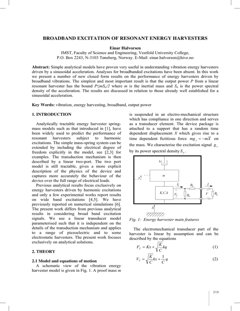
BROADBAND EXCITATION OF RESONANT ENERGY HARVESTERS Einar Halvorsen IMST, Faculty of Science and Engineering, Vestfold University College, P.O. Box 2243, N-3103 Tønsberg, Norway. E-Mail: einar.halvorsen@hive.no Abstract: Simple analytical models have proven very useful in understanding vibration energy harvesters driven by a sinusoidal acceleration. Analyses for broadbanded excitations have been absent. In this work we present a number of new closed form results on the performance of energy harvesters driven by broadband vibrations. The simplest and most important result is that the output power P from a linear resonant harvester has the bound PmSa/2 where m is the inertial mass and Sa is the power spectral density of the acceleration. The results are discussed in relation to those already well established for a sinusoidal acceleration. Key Words: vibration, energy harvesting, broadband, output power 1. INTRODUCTION Analytically tractable energy harvester springmass models such as that introduced in [1], have been widely used to predict the performance of resonant harvesters subject to harmonic excitations. The simple mass-spring system can be extended by including the electrical degree of freedom explicitly in the model, see [2,3] for examples. The transduction mechanism is then described by a linear two-port. The two port model is still tractable, gives a more explicit description of the physics of the device and captures more accurately the behaviour of the device over the full range of electrical loads. Previous analytical results focus exclusively on energy harvesters driven by harmonic excitations and only a few experimental works report results on wide band excitations [4,5]. We have previously reported on numerical simulations [6]. The present work differs from previous analytical results in considering broad band excitation signals. We use a linear transducer model parameterised such that it is independent on the details of the transduction mechanism and applies to a range of piezoelectric and to some electrostatic harvesters. The present work focuses exclusively on analytical solutions. 2. THEORY 2.1 Model and equations of motion A schematic view of the vibration energy harvester model is given in Fig. 1. A proof mass m is suspended in an electro-mechanical structure which has compliance in one direction and serves as a transducer element. The device package is attached to a support that has a random time dependent displacement X which gives rise to a time dependent fictitious force mg x mX on the mass. We characterise the excitation signal g x by its power spectral density S a . Fig. 1: Energy harvester main features The electromechanical transducer part of the harvester is linear by assumption and can be described by the equations K kq (1) FT Kx C VT K 1 kx q C C (2) 319 where FT is the force applied to the mechanical port of the transducer and VT is the voltage across its electrical terminals. The displacement is denoted x and the excess charge on an electrode is denoted q . The transducer is characterised by three parameters: A stiffness K, a capacitance C and an electromechanical coupling factor k. Shown in the figure, are also the load resistor and stray resistances. The total force acting on the proof mass is then F FT mg x bx , (3) where we have added a mechanical damping b. From Newton’s second law and Kirchhoff's laws, the equations of motion for the harvester are Z0 Z0 2 k 2 x Z 0 x x q gx (4) Q * and Z Z* q 0 q 0 kx 0 (5) r r where we have introduced some characteristic quantities. These are the mechanical resonance angular frequency Z 0 K / m , a mechanical excited by an acceleration that has a flat PSD around the resonance of the harvester and has a bandwidth that is larger than that of the harvester. The total output power is found by integrating (7) using the method of [7]. The result is 2 · § rP ¸¸ ¨¨ P r r r L ¹ © P S 2 rL k Q u , (8) 1 (1 / Q k 2 Q)r r 2 which is illustrated in Fig. 2. The power increases with k 2 Q which can be considered a figure of merit for the harvester. For any choice of parameters we always have P d mS a / 2 . (9) We find an optimum load resistance by maximizing (8) over rL. The optimum value is mS a 2 rLO 2 rS 1 (1 / Q k 2 Q)rS 2rS / rP . (10) 2 1 (1 / Q k 2 Q) / rP 1 / rP For vanishing stray electrical losses (rS=0, rP=), the optimum is rLO 1 . quality factor Q mZ 0 / b for the electrically open circuit, dimensionless resistances rD Z 0 CRD (D P, S, L) and r rP (rS rL ) /(rP rS rL ) , and the quantity * KC which has the dimension of a transduction factor. 2.2 Output power Since the energy harvester is linear, it is convenient to analyze in the frequency domain. Let the frequency response of the output current IT to the input acceleration be denoted h (Z ) . It is easily found by Fourier transforming Eqs. (4) and (5) and reads 2 h (Z ) iZk* / (1 k 2 )Z 0 (1 r / Q)Z 2 (6) 2 iZZ 0 1 / Q r (1 Z 2 / Z 0 ) The output PSD delivered into the load is then ^ > @` 2 2 · ˆ § RP ¸¸ h(Z ) S a (Z ) . (7) S (Z ) RL ¨¨ © R P RS R L ¹ In order to predict the output power, we assume constant S a in the following calculations. This is exact for a white noise excitation. In practice, it is a good approximation for a linear harvester that is 320 Fig. 2: Total power delivered to load vs. load resistance for Q 1000 , rS 0 and rP f . In the case of a harmonic excitation, the optima are strongly dependent on the mechanical losses. In our notation the optimal loads for a harmonic excitation rLO are rLO 1 / 1 k 2 (k 2 Q) 2 1 (k 2 Q) 2 and when driven at the undamped resonance 1 k 2 Z 0 or undamped anti-resonance Z 0 respectively. A comparison between the harmonic and broad band cases is made in Fig. 3 which shows contour plots of S (also proportional to the output power for a harmonic excitation). The harmonic case has two optima with very peaked and narrow responses for the optimal choice of load resistance and drive frequency. The broadband optimum load gives close to maximum bandwidth, though the PSD is much lower. Fig. 3: Solid lines: Contours (one decade spacing) of output PSD for rS 0 , rP f , k 2 0 .1 and Q 1000 . Dotted line: optimal load, harmonic excitations. Black spots: local optima, harmonic excitation. Dashed line: optimal load, broad band excitation. 2.3 Proof mass displacement The electrical loading causes damping and affects the motion of the inertial mass. Using the same approach as above, we find the variance of the position: V x oc 2 1 r / Q (1 k 2 )r 2 V x2 (11) 1 k 2 1 (1 / Q k 2 Q)r r 2 where SaQ (12) V x oc 2 3 2Z 0 is the open circuit variance. The RMS displacement is illustrated in Fig. 4. Starting from a small load resistance, the displacement quickly drops as the resistance increases. The maximum electrical damping (minimum RMS displacement) is near the optimum load for small electromechanical coupling, while for large coupling the displacement is small for a wide range of load resistances. As the coupling approaches unity, we see from (11) that the fluctuations diverge. In this limit the system has zero short circuit stiffness, is dominated by damping forces and the fluctuations will be limited by mechanical stoppers. Fig. 4: RMS displacement for rS Q 2 0 , rP f, 1000 and several values of k . 2.4 Second order model It is also possible to apply a broadband excitation to the second order model in [1] which our model maps onto in the limit of small load resistance. Rearranging and iterating (5), we find r q *kx *kx O(r 2 ) (13) Z0 which by insertion into (4) gives the equation of motion of a standard mass-spring system x Z 02 (1 k 2 ) x Z0 Q (1 k 2 Qr ) x gx (14) with undamped resonance 1 k 2 Z 0 and total damping b+be where the electrical damping is (15) be mZ 0 k 2 r . Following the same approach as above, we calculate the power dissipated in the electrical damper for a broadband excitation and find 2 · rL k 2 Q mS a § rP ¨¨ ¸ P (16) 2 © rP rS rL ¸¹ 1 k 2 Qr The maximum output power for this expression is found for the load resistance 321 1 k 2 QrS 2rS / rP 2 (17) rLO rS rP 1 k 2 QrP which predicts an infinite optimum load resistance for vanishing stray electrical losses. From the analysis of the full linear model above, we know that this is wrong. The second order model is only valid for small load resistances and has an electrical damping proportional to the load resistance. Therefore, when trying to apply it beyond its region of validity, the response will be smeared out and cover a wide band instead of approaching the true open circuit resonance. 2 3. DISCUSSION AND CONCLUSION Energy harvesters behave qualitatively quite differently when exposed to broadband instead of harmonic excitations. We have seen that when subject to a wide band excitation the output power vs. load resistance has a different optimum than when the harvester is subject to a harmonic excitation. By analogy with a filter, it is clear that this analysis is valid when the excitation signal has sufficiently large bandwidth compared to that of the harvester and is sufficiently flat over that bandwidth. Our analysis has, of course, relevance when one attempts to harvest from wide band acceleration signals. In addition, a resonant energy harvester designed for a particular operation frequency may have a very narrow bandwidth around that frequency. Therefore, it does not require much line width in the excitation signal before the device operates in a way that is better described by a broadband excitation. When the excitation bandwidth exceeds that of the harvester itself, this must be accounted for. The simpler second order model does not correctly predict the optimal load and is not accurate at the true optimal load. This is different from the case of a harmonic excitation which is accurately described by this model at the resonance even though the anti-resonance is lost. Therefore more physically accurate models, such as the linear model used here, should be used for analysis of broadband excitations. In summary we have analyzed vibration energy harvesters subject to broadband acceleration signals and given closed form solutions of the 322 expected output power, variance of proof mass displacement and optimal load values. A particular simple and useful result is the bound PmSa/2 on output power. Our formalism can be applied also to more general excitation signals by appropriate choice of the acceleration PSD. ACKNOWLEDGEMENTS Stimulating discussions with Svein Husa are gratefully acknowledged. This work was in part supported by regional government funds through the project BTV-Teknologi and in part by the Research Council of Norway through grant no. 176485. REFERENCES [1] C. Williams and R. Yates, Analysis of a Micro-Electric Generator For Microsystems, Transducers ’95 / Eurosensors IX, pp. 369– 372, 1995. [2] R. Amirtharajah and A. Chandrakasan, Selfpowered signal processing using vibrationbased power generation, IEEE J. Solid-State Circuits, vol.33, no.5, pp. 687–695, 1998. [3] N. E. duToit, B. L. Wardle, and S. G. Kim, Design considerations for MEMS-scale piezoelectric mechanical vibration energy harvesters, Integr. Ferroelectr., vol. 71, pp. 121–160, 2005. [4] H. A. Sodano, D. J. Inman, and G. Park, Comparison of Piezoelectric Energy Harvesting Devices for Recharging Batteries, J. Intel. Mat. Syst. Str., vol. 16, pp. 67–75, 2005. [5] E. Lefeuvre, A. Badel, C. Richard, D. Guyomar, and L. Petit, Optimization of piezoelectric electrical generators powered by random vibrations, DTIP 2006, http://hdl.handle.net/2042/6520, Stresa, April 2006. [6] E. Halvorsen, L.-C. J. Blystad, S. Husa, and E. Westby, Simulation of Electromechanical Systems Driven by Large Random Vibrations, MEMSTECH 2007, May 23-26, 2007, Lviv, pp. 117-122. [7] R. S. Phillips in Theory of Servomechanisms, H. M. James, N. B. Nichols, and R. S. Phillips, Eds., McGraw-Hill (1947) 369-370.

![Solution to Test #4 ECE 315 F02 [ ] [ ]](http://s2.studylib.net/store/data/011925609_1-1dc8aec0de0e59a19c055b4c6e74580e-300x300.png)
