Improvement of Micro Solid Rocket Array Thruster for Reliable
advertisement

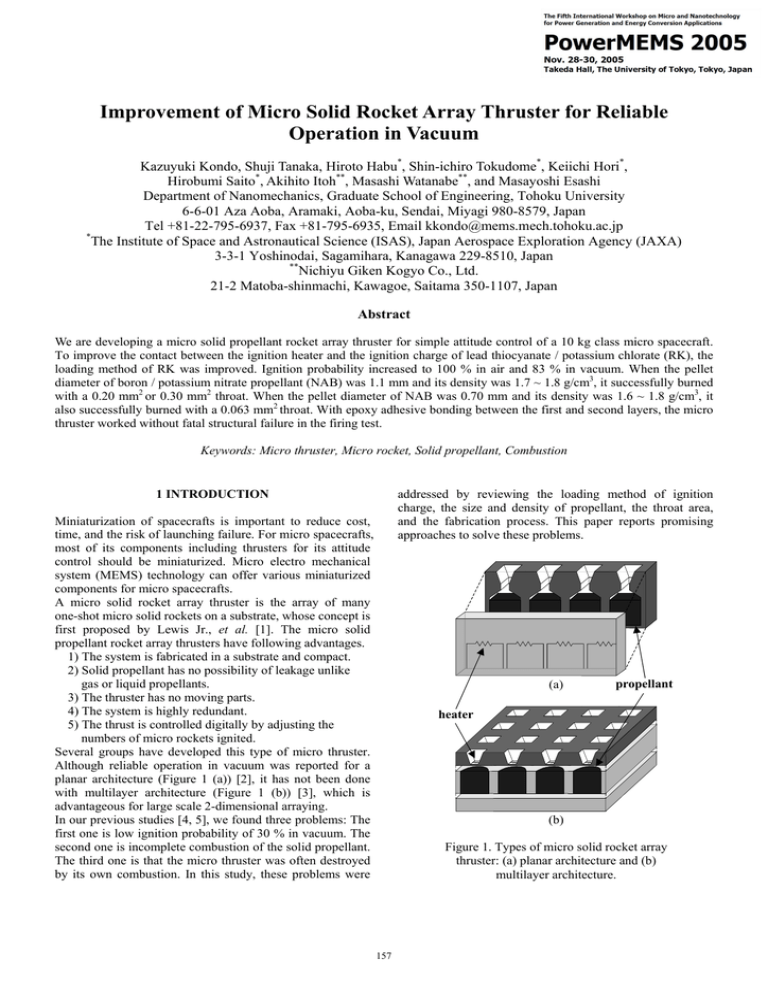
Improvement of Micro Solid Rocket Array Thruster for Reliable Operation in Vacuum Kazuyuki Kondo, Shuji Tanaka, Hiroto Habu*, Shin-ichiro Tokudome*, Keiichi Hori*, Hirobumi Saito*, Akihito Itoh**, Masashi Watanabe**, and Masayoshi Esashi Department of Nanomechanics, Graduate School of Engineering, Tohoku University 6-6-01 Aza Aoba, Aramaki, Aoba-ku, Sendai, Miyagi 980-8579, Japan Tel +81-22-795-6937, Fax +81-795-6935, Email kkondo@mems.mech.tohoku.ac.jp * The Institute of Space and Astronautical Science (ISAS), Japan Aerospace Exploration Agency (JAXA) 3-3-1 Yoshinodai, Sagamihara, Kanagawa 229-8510, Japan ** Nichiyu Giken Kogyo Co., Ltd. 21-2 Matoba-shinmachi, Kawagoe, Saitama 350-1107, Japan Abstract We are developing a micro solid propellant rocket array thruster for simple attitude control of a 10 kg class micro spacecraft. To improve the contact between the ignition heater and the ignition charge of lead thiocyanate / potassium chlorate (RK), the loading method of RK was improved. Ignition probability increased to 100 % in air and 83 % in vacuum. When the pellet diameter of boron / potassium nitrate propellant (NAB) was 1.1 mm and its density was 1.7 ~ 1.8 g/cm3, it successfully burned with a 0.20 mm2 or 0.30 mm2 throat. When the pellet diameter of NAB was 0.70 mm and its density was 1.6 ~ 1.8 g/cm3, it also successfully burned with a 0.063 mm2 throat. With epoxy adhesive bonding between the first and second layers, the micro thruster worked without fatal structural failure in the firing test. Keywords: Micro thruster, Micro rocket, Solid propellant, Combustion addressed by reviewing the loading method of ignition charge, the size and density of propellant, the throat area, and the fabrication process. This paper reports promising approaches to solve these problems. 1 INTRODUCTION Miniaturization of spacecrafts is important to reduce cost, time, and the risk of launching failure. For micro spacecrafts, most of its components including thrusters for its attitude control should be miniaturized. Micro electro mechanical system (MEMS) technology can offer various miniaturized components for micro spacecrafts. A micro solid rocket array thruster is the array of many one-shot micro solid rockets on a substrate, whose concept is first proposed by Lewis Jr., et al. [1]. The micro solid propellant rocket array thrusters have following advantages. 1) The system is fabricated in a substrate and compact. 2) Solid propellant has no possibility of leakage unlike gas or liquid propellants. 3) The thruster has no moving parts. 4) The system is highly redundant. 5) The thrust is controlled digitally by adjusting the numbers of micro rockets ignited. Several groups have developed this type of micro thruster. Although reliable operation in vacuum was reported for a planar architecture (Figure 1 (a)) [2], it has not been done with multilayer architecture (Figure 1 (b)) [3], which is advantageous for large scale 2-dimensional arraying. In our previous studies [4, 5], we found three problems: The first one is low ignition probability of 30 % in vacuum. The second one is incomplete combustion of the solid propellant. The third one is that the micro thruster was often destroyed by its own combustion. In this study, these problems were (a) propellant heater (b) Figure 1. Types of micro solid rocket array thruster: (a) planar architecture and (b) multilayer architecture. 157 2 STRUCTURE 3 PROPELLANT LOADING FOR HIGHER IGNITION PROBABILITY The tested micro thruster has micro solid propellant rockets (φ 0.8 mm × 1 mm or φ 1.2 mm × 1 mm) on a 22 mm × 22 mm substrate as shown in Figure 2. Figure 3 shows the cross-sectional structure of the micro thruster. It consists of three layers: The first silicon layer has nozzles and ignition heaters on diaphragms. The nozzles are fabricated by etching the silicon substrate using ethylene diamine pyrocatechol water (EPW). The ignition heaters are made of Pt/Cr, and have resistance of 60 ~ 450 Ω. The p++ silicon diaphragm, which bursts after ignition, thermally insulates the ignition heaters, and also seals solid propellants. The second glass layer contains the solid propellants, and the third one covers them. The first and second layers are bonded with epoxy adhesive, and then the solid propellants are inserted from the second layer. Finally, the second and third layers are bonded using epoxy adhesive. As a propellant, we selected boron / potassium nitrate (NAB, Nichiyu Giken Kogyo). This is because NAB has ignition temperature as low as 500 ºC, and easily starts to burn in vacuum compared to other propellants such as hydroxyl-terminated polybutadiene / ammonium perchlorate (HTPB/AP) [6], glycidyle azide polymer (GAP) [3], and zirconium perchlorate potassium (ZPP) [3]. φ 0.7 mm × 0.5 mm or φ 1.1 mm × 0.6 mm NAB pellets shaped using a punch and die, are inserted to the propellant cylinders. Lead thiocyanate / potassium chlorate (RK, Nichiyu Giken Kogyo), whose ignition temperature is about 200 ºC, is put between the ignition heater and the NAB pellet as ignition charge. In the previous study, the first and second layers were bonded by anodic bonding technique. In this method, the bonded layer often separated during combustion, because only a part of the silicon surface without the ignition heaters and their wiring is bonded. In this study, we used epoxy adhesive to increase the bonding strength. In this method, the whole substrate surfaces are bonded, and each micro rocket is isolated from other micro rockets. As a result, there is no risk that RK spreads to the neighboring microrockets during loading, which results in the simultaneous ignition of the microrockets. In our previous study [4], the ignition probability remained as low as 30 % due to the poor adhesion of the ignition charge to the ignition heater. This problem was caused by the RK loading method. RK is an explosive fine powder, and is dispersed in acetone to prevent firing. When loading RK, acetone rapidly evaporates from a droplet of the RK-acetone mixture in air, and the powdered RK is difficult to put on the ignition heater. The powdered RK has poor adhesion to the ignition heater, therefore heat transmission from the ignition heater to the RK is not enough to ignite it. In order to solve this problem, we changed the RK loading method. We used a mixture of acetone and isoamyl acetate as a dispersion medium, because evaporation time is long enough to drop wet RK on the ignition heater. For some micro rockets, non-solidified GAP was loaded on RK, and then the NAB pellet was placed on the GAP as shown in Figure 4. The GAP is solidified by its internal reaction without significant shrinkage, and works as an adhesive to ensure the contact between the RK and the ignition heaters. Table 1 shows the result of testing. In air, 100 % RK ignition probability was achieved with and without GAP. Ignition is easy in air, because air helps transmitting the heat from the ignition heater to the RK. 7 3rd layer (Glass) 6 5 2nd layer (Glass) 4 3 2 1st layer (Si) 1 1 Diaphragm 2 Insulating Layer 3 Interconnection 4 Ignition Heater 5 Ignition Charge (RK) 6 Solid Propellant (NAB) 7 Epoxy Adhesive Figure 3. Cross-sectional structure of a micro solid rocket array thruster. 3rd layer (Glass) 2nd layer (Glass) Solid Propellant (NAB) GAP Ignition Charge (RK) 1st layer (Si) 1cm Figure 2. Top view of the micro solid rocket array thruster before loading propellants. Figure 4. Loading method of the propellant with GAP. 158 Table 1. RK ignition probability. Environment Air Vacuum (4.8 kPa) (a) density: 1.63 g/cm3 Ignition probability (ignition / total) With GAP Without GAP 100 % (7/7) 100 % (5/5) 83 % (5/6) 71 % (5/7) 500 µm In vacuum, RK ignition probability was 83 % with GAP and 71 % without GAP. The effect of GAP was confirmed to some extent. Compared to the previous results [4], RK ignition probability was improved from about 30 % to 70 ~ 80 % by improving the RK loading method. The GAP improved the RK ignition probability, but the GAP hardly burned in both air and vacuum. The possible reasons are high pressure deflagration limit (PDL) of GAP (0.63 MPa) [7] and large heat capacity of GAP caused by the contact between the GAP and NAB pellet. (b) density: 1.70 g/cm3 500 µm (c) density: 1.83 g/cm3 4 OPTIMIZATION OF PROPELLANT AND NOZZLE In our previous study [4], most of the NAB pellets did not burn in both air and vacuum, although the RK was ignited. Unburned NAB was observed inside the propellant cylinder after combustion. To find a condition for the perfect combustion of NAB, the micro thrusters with different NAB pellet diameters, NAB pellet densities, throat areas, and diaphragm thicknesses of 2, 4, and 8 µm were prepared, and tested in vacuum at 3.2 kPa. 500 µm Figure 5. Comparison of the nozzles after the combustion of the NAB pellets with different densities. (Pellet diameter: 1.1 mm, Throat area: 0.20 mm2) 4.1 Density of NAB Pellet φ1.1 high Figure 5 compares the nozzles after the combustion of different NAB densities (1.63, 1.70, and 1.83 g/cm3). A significant amount of deposit is found on the nozzle shown in Fig. 5 (b). This deposit was identified as the reaction product of NAB by EDX (energy dispersive X-ray spectroscopy) (see Section 4.3). Inside the nozzle, the NAB did not remain as loaded. Thus, we can judge that the NAB burned successfully in this nozzle. On the other hand, the unburned NAB was found inside the nozzles shown in Fig. 5 (a) and (c). Also, little reaction product was deposited on these nozzles. Thus, we can judge that the NAB did not burn successfully in these nozzles. We observed each nozzle after combustion, and judged the degree of NAB combustion. In Figure 6, each combustion result is plotted using the NAB pellet density and the throat area as parameters. A circle, triangle, and cross represent successful (e.g. Fig. 5 (b)), halfway, and failed combustion (e.g. Fig. 5 (a) and (c)), respectively. When the pellet diameter was 1.1 mm, the NAB pellet successfully burned in the density of 1.7 ~ 1.8 g/cm3 and the throat area of 0.20 mm2 or 0.30 mm2. For the pellet diameter of 0.7 mm, successful combustion was possible in the NAB density of 1.6 ~ 1.8 g/cm3. We have found that there is a suitable range of the NAB density for successful combustion. φ1.1 medium φ1.1 low φ0.7 high φ0.7 medium φ0.7 low 2 Throat area (mm ) 0.3 0.2 0.1 0 destruction 1.5 1.6 1.7 1.8 1.9 2 NAB pellet density (g/cm3) Figure 6. Result of the combustion test. A circle, triangle, and cross represent successful, halfway, and failed combustion, respectively. Generally, a lower density NAB pellet has a larger effective combustion cross-section and is easier to burn. As Figure 6 shows, however, the NAB pellet with too low density is also difficult to burn. The low density pellet with large effective combustion cross-section produces a large amount of gas per time. This gas caused significant pressure gap between inside and outside the combustion chamber at the initial stage of combustion. NAB combustion could be extinguished after the diaphragm burst due to rapid 159 Light intensity (a.u.) Figure 5 (a) Nitrogen atoms in KNO3 become nitrogen gas during combustion and go out. The EDX result indicates that the deposit on the nozzle is burned NAB. Figure 5 (b) RK + NAB 5 CONCLUSION NAB combustion The ignition probability increased to 100 % in air and 83 % in vacuum by improving the loading method of the ignition charge (RK). When the pellet diameter of the NAB propellant was 1.1 mm and its density was 1.7 ~ 1.8 g/cm3, it successfully burned with a 0.20 mm2 or 0.30 mm2 throat. When the NAB pellet diameter was 0.7 mm and its density was 1.6 ~ 1.8 g/cm3, it also successfully burned with a 0.063 mm2 throat. We found that a suitable density of the NAB pellet is around 1.7 g/cm3, and that a suitable throat area is around 20 % of the cross-section of the NAB pellet. Using epoxy adhesive for bonding the first and second layers, the micro thruster worked without fatal structural failure in the firing test. Ignition 0 50 100 150 Time (ms) Figure 7. Comparison of the combustion times for Figure 5 (a) and (b). depressurization. Because this rapid depressurization could be milder for smaller diameter NAB pellets, the φ 0.7 mm NAB pellet has a wider range of suitable density (1.6 ~ 1.8 g/cm3) than the φ 1.1 mm NAB pellet (1.7 ~ 1.8 g/cm3). Also, the combustion surface of the fragile NAB pellet with low density could be easily blown off. Figure 7 compares the combustion time for Figure 5 (a) and (b). The light from flame was detected by a photo diode. The NAB pellet with a density of 1.70 g/cm3 burned for 112 ms, but that with a density of 1.63 g/cm3 burned only for 2 ms. This result supports the above explanations. REFERENCES [1] David H. Lewis Jr., Siegfried W. Janson, Ronald B. Cohen and Erik K. Antonsson, “Digital Micropropulsion,” Sensors and Actuators A, 80, pp. 143-154, 2000. [2] K. L. Zhang, S. K. Chou, S. S. Ang, X. S. Tang, “A MEMS-based solid propellant micro thruster with Au/Ti igniter,” Sensors and Actuators A, 122, pp. 113-123, 2005. [3] Carole Rossi, Benoît Larangot, Denis Lagrange, Amar Chaalane, “Final characterizations of MEMS-based pyrotechnical microthrusters,” Sensors and Actuators A, 121, pp.508-514, 2005. [4] Kazuyuki Kondo, Shuji Tanaka, Hiroto Habu, Shin-ichiro Tokudome, Keiichi Hori, Hirobumi Saito, Akihito Itoh, Masashi Watanabe and Masayoshi Esashi “Vacuum test of a micro-solid propellant rocket array thruster,” IEICE Electronics Express, 1, 8, pp. 222-227, 2004. [5] Masashi Watanabe, Akihito Itoh, Hiroto Habu, Shin-ichiro Tokudome, Keiichi Hori, Kazuyuki Kondo, Shuji Tanaka, Masayoshi Esashi, “Ignition Charge for Solid Propellant Micro-Thruster,” Proc. of Asian Joint Conference on Propulsion and Power, Kitakyushu, Japan, January 27-29, 2005, AJCPP2005-21004. [6] D. Teasdale, V. Milanovic, P. Chang, K. S. J. Pister, “Microrockets for smart dust,” Smart Mater. Struct., 10, pp. 1145-1155, 2001 [7] K. Hori, M. Kohno, A. Volpi, C. Zanotti, K. Katoh, S. Miyazaki, “Burning Rate and Pressure Deflagration Limit (PDL) Characteristics of a GAP/AP Propellant System,” Proc. of The fifth International Sysmposium on Special Topics in Chemical Propulsion, Stresa, Italy June, 2000, pp. 513-522. 4.2 Throat Area As we discussed above, when the throat areas are 0.20 mm2 and 0.063 mm2, φ 1.1 mm and φ 0.70 mm NAB pellets successfully burned, respectively. In both cases, the throat area is approximately 20 % of the cross-section of the NAB pellet. Comparing 0.30 mm2 and 0.063 mm2 throat, φ 0.70 mm NAB pellet did not burn successfully with the 0.30 mm2 throat. This can be explained by the rapid depressurization mentioned above. When the throat areas were 0.023 and 0.0049 mm2, the silicon layer with the nozzles was destroyed by combustion. Robust small diaphragm and/or choking at the narrow throat produced high pressure in the combustion chamber. In our previous study, the silicon and glass layers, which were bonded by anodic bonding technique, often separated by combustion. In this study, by using epoxy adhesive bonding, these two layers did not separate as mentioned above, and the micro thruster worked without fatal structural failure in the firing test. 4.3 Analysis of Unburned and Burned NAB After the combustion test, the deposit was observed on the nozzle as shown in Fig. 5 (b). We performed EDX to confirm the atomic composition of NAB and the deposit. 5 % nitrogen was detected in the NAB, but no nitrogen was detected in the deposit. The main reaction formula of NAB combustion is aB + bKNO3 → cB2O3 + dKBO2 + eN2 + ... (1) 160


