The Design of a Hybrid High-speed Electrical Micromachine
advertisement

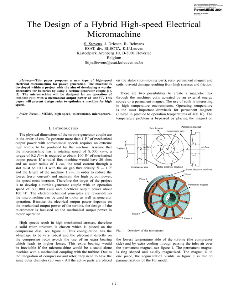
The Design of a Hybrid High-speed Electrical Micromachine S. Stevens, J. Driesen, R. Belmans ESAT, div. ELECTA, K.U.Leuven Kasteelpark Arenberg 10, B-3001 Heverlee Belgium Stijn.Stevens@esat.kuleuven.ac.be Abstract— This paper proposes a new type of high-speed electrical micromachine for power generation. The machine is developed within a project with the aim of developing a worthy alternative for batteries by using a turbine-generator couple [1], [2]. The micromachine will be designed for an operation of 500, 000 rpm with a mechanical output power of 100 W . This paper will present design rules to optimize a machine for high speed. Index Terms— MEMS, high speed, micromotor, microgenerator on the stator (non-moving part), resp. permanent magnet and coils to avoid damage resulting from high stresses and friction. There are two possibilities to create a magnetic flux through the machine: coils actuated by an external energy source or a permanent magnet. The use of coils is interesting in high temperature environments. Operating temperature is the most important drawback for permanent magnets (limited in practice to operation temperatures of 400 K). The temperature problem is bypassed by placing the magnet on I. I NTRODUCTION Bow tie rotor Permanent magnet Compressor inlet The physical dimensions of the turbine-generator couple are in the order of cm. To generate more than 1 W of mechanical output power with conventional speeds requires an extreme high torque to be produced by the machine. Assume that the micromachine has a rotating speed of 5, 000 rpm, a torque of 0.2 N m is required to obtain 100 W of mechanical output power. If a radial flux machine would have 20 slots and an outer radius of 1 cm, the total current through a slot must be 100 A with the air gap flux density B = 1 T and the length of the machine 1 cm. In order to reduce the forces (resp. current) and maintain the high output power, the speed must increase. Therefore the target of the project is to develop a turbine-generator couple with an operation speed of 500, 000 rpm and electrical output power about 100 W . The electromechanical principles are reversible so the micromachine can be used in motor as well as generator operation. Because the electrical output power depends on the mechanical output power of the turbine, the design of the micromotor is focussed on the mechanical output power in motor operation. Airflow Turbine Compressor disc Airflow Rotor electrical machine Stator electrical machine Phase 1 Phase 2 Permanent magnet Phase 3 Phase 1 High speeds result in high mechanical stresses, therefore a solid rotor structure is chosen which is placed on the compressor disc, see figure 1. This configuration has the advantage to be very robust and the placement directly on the compressor rotor avoids the use of an extra bearing which leads to higher losses. This extra bearing would be inevitable if the micromachine would be a stand alone machine with a mechanical coupling with the turbine. Due to the integration of compressor and rotor, they need to have the same outer diameter (20 mm). All the active parts are placed 112 Fig. 1. Overview of the micromotor the lowest temperature side of the turbine (the compressor side) and by extra cooling through passing the inlet air over the permanent magnet, see figure 1. The permanent magnet is ring shaped and axially magnetized. The magnet is in one piece, the segmentation visible in figure 1 is due to parametrization of the FE model. In figure 2 an overview of the magnetic flux path is given. The magnet creates a flux that crosses the air gap and enters the bow tie shaped rotor. From here it goes towards the outer diameter where it again crosses the air gap towards the stator teeth. The flux paths close via the stator back iron to the permanent magnet. Because of mechanical stability, the rotor must be symmetrical. The number of pole pairs is derived in section II. The windings on the stator are three phase distributed windings which are connected as R − S − T − R − S − T , see in figure 1. Stator Rotor specific resistivity. The parameter r is the outer radius of the conductor and J(r) is the current density on the outer surface. Figure 3 shows the influence of the radius of the conductor. In this example copper is used (ρe = 1.724.10−8 Ωm and µ = 4π.10−7 ). It can be seen that the current density is not constant over the cross-section of the conductor. If the current density on the outer surface of the conductor is 7 A/mm2 than in the center it will be 5.93 A/mm2 for r = 0.5 mm. This results in a total current of 5.1 A instead of 5.5 A in case of a constant current density distribution. Figure 3 clearly shows that the smaller the radius of the conductor the smaller the skin effect. The reason why two pole pairs are chosen can be explained by the use of figure 3. The total current for f = 33, 334 Hz is 4.3 A (four pole pairs), this is almost 1 A less than if two pole pairs were used. 7 Permanent magnet Re(J) [A/mm2] 6.5 Flux path 6 5.5 5 4.5 4 3.5 −0.5 −0.2 0 Position [mm] 0.2 0.5 r = 0.5 mm and f = 16667 Hz r = 0.2 mm and f = 16667 Hz r = 0.5 mm and f = 33334 Hz 0 Fig. 2. Im(J) [A/mm2] −1 Magnetic flux path −2 −3 −4 The name hybrid is chosen because this micromachine combines the principles of a permanent magnet and a reluctance machine. In the next sections the following topics are more explained into detail: the skin effect, the electrical time constant and the mechanical stresses that appear in the rotor. The aim is to come to some design rules for high-speed machines. In the last section, the first results of a linear static FE analysis of the micromotor are reported. II. T HE SKIN EFFECT If the machine is operating at 500, 000 rpm, the electrical frequency f is 16, 667 Hz when four poles are used. The alternating current induces eddy currents in the conductor. Due to the eddy currents there is a shift in current density from the inside towards the outside of conductor. This effect is called skin effect which augments the effective resistance of the coils. The skin effect for one conductor is described by a Bessel function of the first sort: √ I0 ( j m.x) J(x) = J(r). √ (1) I0 ( j m.r) q Herein is m = ωµ ρe and x the position on the radius. ω is defined as 2πf , µ is the magnetic permeability and ρe is the 113 −5 −0.5 Fig. 3. −0.2 0 Position [mm] 0.2 0.5 Current density for different frequencies by radius r = 0, 5 mm Due to the skin effect, the AC resistance RAC increases with frequency. Using following equation [3]: RAC sinh(2ξ) + sin(2ξ) =ξ RDC cosh(2ξ) − cos(2ξ) (2) Herein is RDC the resistance if DC current was used. ξ is the normalized conductor height and is equal to hδ , with h the conductor height and δ the skin depth. δ is defined as q 2 1 ωµσ with σ = ρe . Figure 4 shows that working with a frequency of f = 16, 667 Hz almost doubles the DC resistance value, for f = 33, 334 Hz it triples. 3.5 III. E LECTRICAL TIME CONSTANT To control the machine in a accurate way, it is necessary diminish the time constant of the electrical circuit. This time constant is proportional to: 3 2.8 L (8) R Herein is L the inductance of the system and R the resistivity 2 of the electrical system. The inductance L is defined as N< with < the reluctance of the magnetic circuit. All the quantities are time averaged values. Rewriting equation (8): τ∼ RAC/RDC 2.5 2 1.8 1.5 1 τ ∼ ∼ 0 Fig. 4. 5 10 15 16.7 20 25 30 Frequency [kHz] 35 40 45 50 In equation (9) the electrical resistance is replaced by ρef f (f )lc . One option to minimize the time constant of the Ac machine is to make < as big as possible by saturation of the rotor during operation. Together with the fact that the machine has two air gaps makes the reluctance already very high. The copper loss can be written as [4]: = = = R(f )I 2 ρef f (f )lc N 2 2 J Ac Ac ρef f (f )lc N Ac J 2 (3) (4) Pmech ∼ N Ac Jlc fmech If the assumption is made that the magnet produces a constant flux Φ through the machine and assuming that < is constant, it can be seen that: <Φ = N JAc (5) Herein is ρef f is the effective specific resistivity, lc the length of one winding, N the number of windings and Ac the effective conductor surface. The mechanical output can be written as [4]: (6) Herein is fmech the mechanical rotating frequency of (f )J loss 8, 333 Hz. In order to minimize PPmech ∼ ρfemech , two parameters can be adapted. ρef f can be minimized in two ways, connecting the conductors in parallel and minimization of f by reducing the number of poles. The second parameter, the current density J, must be as small as possible. This comes with a drawback. To maintain the mechanical output power, the total effective conductor area N Ac and/or the winding length lc must increase. The effective conductor area N Ac is limited by: kf Ag ≥ N Ac (9) 33.3 Increase of resistance as function of frequency Ploss N2 <R N Ac <ρef f (f )lc (7) Herein is kf the fill factor and Ag the slot area. To maximize the available space for conductors, kf has to be maximized. The fill factor depends on the slot geometry, the insulation layer, geometry of the conductor and stacking arrangement. To maximize kf one could think of a conductor that fits perfectly in the slot, consists of only one turn and a very thin insulation layer. To further increase N Ac , the teeth of the stator have to be made smaller so that Ag can increase. (10) With <Φ = cte. Substituting equation (10) in equation (9): τ ∼ 1 ρef f (f )Jlc (11) A conclusion based upon equation (11) is to make the current density J as big as possible and the conductors as long as possible (do not interpret this as maximizing N ). This is partly inconsistent with the discussion in section II where the current density must be as low as possible. This will be a trade off between control requirements and torque. IV. M ECHANICAL STRESSES Rotating at high speed, the rotor stresses are not negligible anymore and become a difficult design problem on its own. To get an idea about the stresses that act in a solid rotor disc, a simple calculation is made. To calculate these stresses following formulas are used [5]: A B σa σr 3+ν 2 2 ρω (ri + ro2 ) 8 3+ν 2 2 2 = ρω ri ro 8 B 1 + 3ν 2 2 = A+ 2 − ρr ω r 8 B 3+ν 2 2 = A− 2 − ρr ω r 8 = (12) (13) (14) (15) (16) 114 Herein are ri and ro the inner resp. the outer radius of the rotor. ρ is the mass density of the material and ν the poisson coefficient. The constants A and B are determined by the fact that σr (ri ) and σr (ro ) are zero. As can be seen from the equations, the stresses depend on the square of the speed and linear on the mass density. Assume a mass density of 7000 − 8000 kg/m3 and a poisson coefficient of 0.3, than figure 5 is obtained (ri = 2.5 mm and ro = 10 mm). From ! ! 600 sigmar [MPa] 500 400 300 200 100 0 3 4 5 6 7 8 9 r [m] 10 −3 x 10 2000 rho = 7000 rho = 8000 sigmaa [MPa] 1500 Fig. 6. Torque calculation with a static analysis 1000 500 0 VI. C ONCLUSION 3 4 5 6 7 r [m] Fig. 5. 8 9 10 −3 x 10 Stresses in different materials this figure it is expected that the azimuthal stresses are around 1000 M P a. It must be mentioned here that the rotor is not a disc but a bow tie shaped rotor. Therefore further FE analysis is required to determine the stresses. V. FE ANALYSIS A linear static analysis is performed on the machine. At each step the rotor is turned 5◦ . The two coils of one phase are excited and the torque acting on the rotor is calculated with the use of the Maxwell-stress tensor. Two results with different meshes are shown in figure 6. Due to the time consuming calculations the adaptive meshing was limited to only two steps. The difference between the two results (40, 000 and 60, 000 nodes) is marginal. As can be seen in figure 6, each time the rotor switches a tooth, the torque fluctuates from positive to negative (in figure 6 this occurs six times because the rotor is only turned π rad and there are 12 teeth). This is due to the fact that the rotor is still overlapping a tooth on the left side of the rotor. A higher concentration of flux is passing through this area which causes the error in the torque computation. One step further the same occurs at the other side of the rotor. This torque ripple would probably be less explicit if a non-linear analysis was performed because the material would saturate at this point. If an interpolation (polynomial of order 6) is made through the points of the torque curve, a sinusoidal shaped curve which passes through zero, is obtained, as expected because of symmetry. 115 In this paper the problems in designing a high speed micromotor are discussed and design rules are proposed. The conclusions are that the electrical frequency must be as low as possible to minimize the copper loss, the conductor length lc should be as long as possible to maximize the torque and minimize the electrical time constant. The choice of the effective conductor area N Ac depends on whether or not the required output power can be obtained or not. From the point of view of controlling, N Ac should be as small as possible, to maximize the torque it should be as large as possible. The next step in realizing the micromotor is quantifying these parameters and implementing them in an extensive electromagnetic as well as mechanical FE analysis. R EFERENCES [1] K.U.Leuven, “powermems project.” http://www.powermems.be. [2] J. Peirs, D. Reynaerts, and F. Verplaetsen, “A microturbine for electric power generation,” Sensors and Actuators A, no. 113, pp. 86–93, 2004. [3] V. Ostovic, Computer-aided Analysis of Electric Machines: A Mathematica approach. Prentcie Hall, 1994. [4] S. Stevens, J. Driesen, and R. Belmans, “A brief overview of power generating micro electromechanical systems,” in Intelligent Energy Conversion, (Delft, The Metherlands), p. 7, IEEE Young Researchers Symposium, March 2004. [5] C. Biezeno and R. Grammel, Engineering Dynamics, vol. 3. Blackie and Son Ltd., 1954.


