III. Bandwidth Basics 32
advertisement
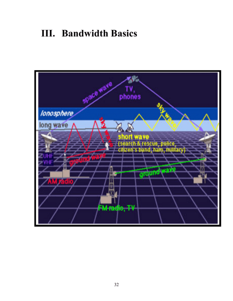
III. Bandwidth Basics 32 III. Bandwidth Basics Transmission and Reception Modern communications and consumer electronic devices such as TV and radio use radio waves for their transmission and reception of data. Any part of the electromagnetic spectrum will do in theory but for our purposes in the twentieth and twenty-first centuries radio waves are the bandwidth of choice, though microwaves have been used and are still in use in some cases. Communications consists of at least one transmitter supplying the signal and at least one receiver. In fact, the more receivers the better if you are a modern commercial radio station trying to sell advertising! The communication link between the transmitter and receiver is established as follows. The transmitter, a radio or TV station, broadcasts a signal by pulse radio waves with around 50,000 Watts of power. This enormous power decreases rapidly with distance from the transmission source and diminishes as the inverse square of distance. Power flux equals = power / area. Imagine a spherical pulse of a radio wave originating at the station. The radius of this spherical pulse grows at the speed of light rapidly increasing the surface area of the pulse. The surface area of the pulse grows larger quite rapidly. Since the surface area of a sphere is 4 * pi * r^2, the surface area grows with the square of the radius. Since power flux is inversely proportional to area, it is readily established the power flux decreases as 1/r^2. This inverse square phenomenon is central to most of physics particularly in fundamental forces of nature like Coulomb’s force and Newton’s Law of Universal Gravitation. It’s the same play with only the actors and stage having been changed. By the time you pick up a signal with your radio or TV, the signal has faded to a faint milliWatt level. Distance isn’t the only factor involved in radio transmission. Radio waves bounce off of all kinds of things. When they bounce off buildings or clouds, some of the radio wave is reflected and some of it is absorbed as heat. The atmosphere attenuates the signal power too. Every little bit of energy you receive has been on a wild ride at the speed of light, going everyplace imaginable before being partially absorbed by the electrons in your antenna. This tiny little “vapor” of energy still carries the signal modulations and information sent by the transmitter and is sufficiently strong for the receiver to decode and play the signal. There are two schemes for signal modulation in wide use. One is AM or amplitude modulation, the other is FM or frequency modulation. Have you ever seen a record player? (Some people call them turntables.) Your parents surely have and with any luck they still have one. The tiny grooves in a 33-rpm record vibrate the needle of the record player creating mechanical vibrations that are transformed into electrical pulses that are amplified and then played by a speaker. 33 The AM modulation scheme resembles the record player. The frequency of an AM station only plays the role of an identifier. The receiver, your radio, filters out all other frequencies except the frequency of the channel you are tuning to. The frequency carries no signal information and only serves as a means to separate one radio station’s transmission from another. The signal information containing the actual sound is carried by modulating the amplitude of the radio wave creating little “grooves” in the signal strength resembling the grooves on a 33-rpm record. These tiny modulations in radio wave amplitude are turned into sound waves in exactly the same manner as for the record player. Another more successful and technologically advanced method of communication is the FM modulation scheme. All sounds are of a particular frequency. Middle C on the piano corresponds to 128 Hz. When you listen to music or hear someone’s voice you are bathed in a shower of sound waves all of different frequencies. Why not allow these changes of frequency to be encoded onto a radio wave of much higher frequency that can be decoded back into a sound wave of the original frequency. An example always helps. Suppose you want to broadcast the middle C of a piano from your radio station to some remote listener. This picture is actually a little bit too simple, we eliminate some fine detail, but it illustrates the main idea. Play middle C. A 128-Hz sound wave is produced. The carrier wave frequency of the radio station is 100,000,000-Hz. Add the middle C frequency to the carrier wave frequency and broadcast a 100,000,128-Hz signal. The receiving radio at the other end “chops off” the extra 100,000,000-Hz and plays the 128Hz signal. The simple change from amplitude modulation to frequency modulation was a significant improvement. Although it is more complicated to design an FM receiver than an AM receiver, frequency is less affected during signal transit than amplitude, resulting in greater signal fidelity for FM signals. There are more modulation schemes and electrical engineers, academics and devoted amateurs, are always coming up with new ones. Here are a few that are popular: CW, USB, and LSB. FM is further divided into WFM, wide band FM, and NFM, narrow band FM. WFM is the most popular FM and so is often referred to as just FM. Every transmitter and receiver combination needs to be tuned into a certain frequency in order to communicate with one another. Although possible, tuning into amplitude for obvious reasons is extremely impractical. Frequency is the only natural choice. It is easy to construct a high-pass filter circuit out of a resistor and a capacitor. A high-pass filter allows only signals above a certain cutoff-frequency to pass through unimpeded. Everything below the cutoff is diminished or for practical intents and purposes, virtually eliminated. A low-pass filter functions similarly and allows only frequencies below a certain cutoff to pass by unimpeded. Using a combination of high-pass and low-pass filters, one can filter out all the undesired frequencies and focus on a narrow bandwidth. All of this is based on the concept of resonance. An opera soprano singing at the natural frequency of a crystal glass can shatter it if her sound waves carry sufficient power. Wind blowing at the right frequency was enough to demolish the Tacoma Narrows Bridge in a few hours. This spectacular event was captured on film and there are video clips of it on the Internet. The glass wouldn’t shatter nor would the bridge collapse if the 34 frequency weren’t a resonant one. The high-pass and low-pass filters operate on a similar principle. Certain frequencies resonate through the circuit while others do not. Activity 1.1 Name ________________________ Date ______________ Class _________________ Investigating Frequency Allocations for AM Radio, FM Radio, UHF TV and VHF TV. You Need: • A Television able to receive several UHF and VHF channels. • An AM/FM radio with good reception. A decent quality antenna helps. • Winradio Communications Receiver Anybody can find a radio station or television station by twiddling a knob and twisting a dial. It’s much more interesting to try to find these stations by tuning directly to their frequencies. In this lab you will tune to an AM station on a radio and then try to find its frequency by tuning to it using the Winradio communications receiver. You’re goal is to have both the receiver and the radio, side by side, receiving the same frequency. You’ll do the same for FM stations. You might notice a pattern how radio stations are numbered with their frequencies. You’ll find the range of frequencies occupied by the AM and FM bands by finding the lowest and highest frequency stations in each bandwidth. Switch the receiver mode from AM to FM mode and hear how the same signal sounds under different demodulating schemes. Okay, so that’s not such a big deal. How about a real challenge? Television broadcasts simultaneously include an audio band alongside a video band. You can hear the visual part of the band but it just sounds like noise. You can still find the audio part of the band. What modulation scheme do they use? AM or FM? Something else? You can find out by switching modes once you lock on to a TV channel with your receiver. The VHF (Very High Frequency) channels on your TV correspond to the upper dial with the smaller numbers starting at 2 going up to 13. The UHF (Ultra High Frequency) channels belong to the lower dial with higher numbers starting at 22. If your TV doesn’t have dials just tune it regularly noting where VHF and UHF begin and end. It is important that your TV is not connected to a cable box because the frequencies won’t match and even if they did cable companies use odd modulation schemes to protect their product. Part A. AM Radio Call Letters Station number Broadcast frequency Location 35 Lowest AM frequency received _______________________ Highest AM frequency received _______________________ AM frequency range from experiment __________________ Size of AM bandwidth ______________________________ Part B. FM Radio Call Letters Station number Broadcast frequency Location Lowest FM frequency received _______________________ Highest FM frequency received _______________________ FM frequency range from experiment __________________ Size of FM bandwidth ______________________________ Part C. VHF TV Call Letters Station number Broadcast frequency Location Lowest VHF frequency received _______________________ Highest VHF frequency received _______________________ VHF frequency range from experiment __________________ Size of VHF bandwidth ______________________________ Best mode ________________________________________ (e.g. WFM, NFM, AM…) Part D. UHF TV Call Letters Station number Broadcast frequency Location Lowest VHF frequency received _______________________ 36 Highest VHF frequency received _______________________ VHF frequency range from experiment __________________ Size of VHF bandwidth ______________________________ Best mode ________________________________________ (e.g. WFM, NFM, AM…) Frequency Allocation Chart Now that you have some raw data to work with, you can create a frequency allocation table of the bandwidths you’ve investigated. Use a separate color for AM, FM, UHF and VHF. Your graph may be linear or logarithmic (based on powers of ten). Questions 1. How well does your frequency allocation chart match the official United States Frequency Allocations Chart? (The United States Frequency Allocations Poster is available as a PDF file and can be viewed using Acrobat reader or some other PDF viewer.) 2. What fraction of the total bandwidth of a VHF TV signal is audio? Video? (You need to consult handbooks or the Internet to find this out.) 3. As you can well image by looking at the USFA chart, there’s a lot more to the radio bandwidth than AM, FM, UHF, and VHF. Find some interesting stuff like weather stations or aircraft communications. What’s the weather like one or two states away? What’s air traffic control up to? 4. SETI is an acronym for the Search for Extra-Terrestrial Intelligence. What kind of radio signals are they hoping to find? How are they modulated? 5. Investigate an actual event of someone broadcasting an illegal signal over a bandwidth that belonges to someone else. What happened? “Captain Midnight” is a famous example of this. Can you find others? What happened? 37 6. What is Bunny Hunting? No, it has nothing to do with Elmer Fudd or Waskally Wabbits. 38
