Analysis of LOFAR High Band Antenna Design
advertisement

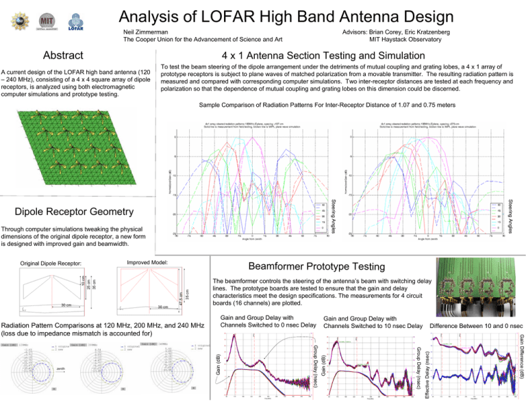
Analysis of LOFAR High Band Antenna Design Neil Zimmerman The Cooper Union for the Advancement of Science and Art Abstract Advisors: Brian Corey, Eric Kratzenberg MIT Haystack Observatory 4 x 1 Antenna Section Testing and Simulation A current design of the LOFAR high band antenna (120 – 240 MHz), consisting of a 4 x 4 square array of dipole receptors, is analyzed using both electromagnetic computer simulations and prototype testing. To test the beam steering of the dipole arrangement under the detriments of mutual coupling and grating lobes, a 4 x 1 array of prototype receptors is subject to plane waves of matched polarization from a movable transmitter. The resulting radiation pattern is measured and compared with corresponding computer simulations. Two inter-receptor distances are tested at each frequency and polarization so that the dependence of mutual coupling and grating lobes on this dimension could be discerned. Sample Comparison of Radiation Patterns For Inter-Receptor Distance of 1.07 and 0.75 meters Through computer simulations tweaking the physical dimensions of the original dipole receptor, a new form is designed with improved gain and beamwidth. Improved Model: Gain and Group Delay with Channels Switched to 10 nsec Delay Difference Between 10 and 0 nsec Effective Delay (nsec) Group Delay (nsec) Group Delay (nsec) zenith Gain and Group Delay with Channels Switched to 0 nsec Delay Gain Difference (dB) Radiation Pattern Comparisons at 120 MHz, 200 MHz, and 240 MHz (loss due to impedance mismatch is accounted for) Gain (dB) 30 cm The beamformer controls the steering of the antenna’s beam with switching delay lines. The prototype boards are tested to ensure that the gain and delay characteristics meet the design specifications. The measurements for 4 circuit boards (16 channels) are plotted. Gain (dB) 35 cm 47.5 cm 10 cm 30 cm Beamformer Prototype Testing 25 cm 35 cm Original Dipole Receptor: Steering Angles Steering Angles Dipole Receptor Geometry


