Document 14386201
advertisement
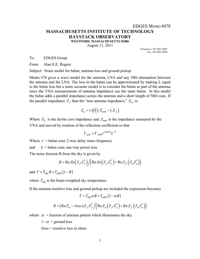
EDGES MEMO #078 MASSACHUSETTS INSTITUTE OF TECHNOLOGY HAYSTACK OBSERVATORY WESTFORD, MASSACHUSETTS 01886 August 11, 2011 Telephone: 781-981-5407 Fax: 781-981-0590 To: EDGES Group From: Alan E.E. Rogers Subject: Noise model for balun, antenna loss and ground pickup Memo #76 gives a wave model for the antenna, LNA and any 50 attenuation between the antenna and the LNA. The loss in the balun can be approximated by making L equal to the balun loss but a more accurate model is to consider the balun as part of the antenna since the VNA measurements of antenna impedance use the same balun. In this model the balun adds a parallel impedance across the antenna and a short length of 50 coax. If the parallel impedance Z f than the “true antenna impedance,” Z a , is Z a 1.0 1 Z ant 1 Z f Where Z f is the ferrite core impedance and Z ant is the impedance measured by the VNA and moved by rotation of the reflection coefficient so that ant vna e 2 i L1 Where = balun coax 2-way delay times frequency and L = balun coax one-way power loss The noise fraction B from the sky is given by B Re Za Z f Z *f Re Za Z f Z *f Re Z f Z a Z a* and T Tsky B Tamb 1 B where Tsky is the beam weighted sky temperature. If the antenna resistive loss and ground pickup are included the expression becomes T Tsky B Tamb 1 B B Re Z a rloss Z f Z *f Re Z Z Z Re Z Z Z a f * f f where = fraction of antenna pattern which illuminates the sky. 1 = ground loss rloss = resistive loss in ohms 1 * a a Measurement of Z f If the balun is disconnected from the antenna vna now measure open e 2 i L Z f 50 Z f 50 which can be inverted to obtain z f Z f 50 1 1 where open e2 i L1 2
