MR-XRT at 1.5T, the UMC Utrecht hybrid MRI linac
advertisement

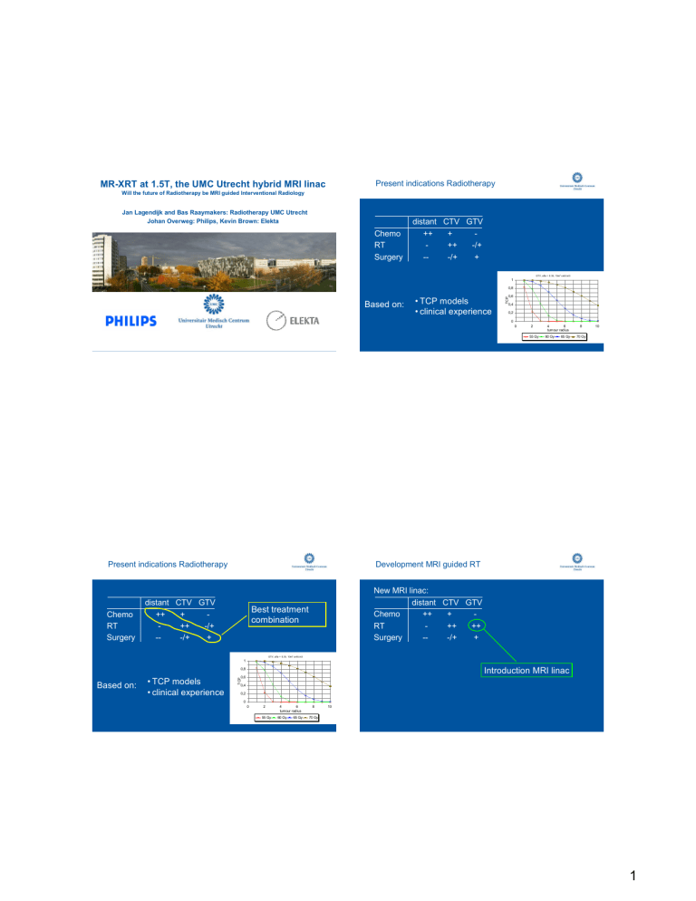
MR-XRT at 1.5T, the UMC Utrecht hybrid MRI linac Present indications Radiotherapy Will the future of Radiotherapy be MRI guided Interventional Radiology Jan Lagendijk and Bas Raaymakers: Radiotherapy UMC Utrecht Johan Overweg: Philips, Kevin Brown: Elekta Chemo RT Surgery distant CTV GTV ++ + ++ -/+ --/+ + GTV, alfa = 0.35, 10e7 cell/cm3 1 0,8 • TCP models • clinical experience 0,6 TCP Based on: 0,4 0,2 0 0 2 55 Gy Present indications Radiotherapy Chemo RT Surgery 4 6 tumour radius 60 Gy 65 Gy 8 10 70 Gy Development MRI guided RT distant CTV GTV ++ + ++ -/+ --/+ + New MRI linac: distant CTV GTV Chemo ++ + RT ++ ++ Surgery --/+ + Best treatment combination GTV, alfa = 0.35, 10e7 cell/cm3 1 Introduction MRI linac 0,8 • TCP models • clinical experience 0,6 TCP Based on: 0,4 0,2 0 0 2 55 Gy 4 6 tumour radius 60 Gy 65 Gy 8 10 70 Gy 1 Development MRI guided RT Treatment combinations New MRI linac: distant CTV GTV Chemo ++ + RT ++ ++ Surgery --/+ + Present day: distant CTV GTV Chemo ++ + RT ++ -/+ Surgery --/+ + Introduction MRI linac T2 weighted MRI sequence cervix GTV primary tumor New MRI linac: distant CTV GTV Chemo ++ + RT ++ ++ Surgery --/+ + percentage of primary radiotherapy patients 0% 100% Cine MRI 1.5 T bladder CTVnodes (path.lymph nodes) GTV pathological lymph nodes (left) rectum CTVprimary (cervix, corpus uteri) GTV pathological lymph nodes (right) irregular breathing von Hippel Lindau kidney tumour T2-weighted 2 MRI-linac for renal cancer • MRI-linac potential (RT sites) Renal cancers are not treated with radiotherapy: – Kidney movements, large PTV – Kidney is very sensitive for radiation damage – Normal tissue is in close proximity (bowel, liver) Planning study: ablative dose feasible (evt. supported by breath-hold) MRI-linac new possibilities Site Amount of gain - Kidney* +++ - Liver metastasis* +++ - Pancreas* +++ - Mesothelioma* +++ - Ovary cancer* ++ - Retroperitoneal sarcoma* ++ - Colon ++ - Lymph node metastasis +++ - Stomach + - Gall bladder + - Pyelum / ureter + - Thymoma ++ - Breast +++ Site Amount of gain - Prostate ++ - Cervix +++ - Head and Neck Lung ++ + - Rectum Esophagus Brain Bladder ++ + ++ + Reason Dose GTV↑, intra-fraction control, deformation Dose GTV↑, shrinkage, deformation, inter-/intra-fraction Dose GTV↑, spare normal tissue Dose lung tissue↓, compensate for breathing Dose GTV↑, (+ chemo) omit surgery Dose GTV↑, (+ chemo) omit surgery Dose GTV↑, visualize CTV, normal tissue Dose GTV↑, intra-fraction control Preferred paradigm Radiotherapy 2010 - … Approach GTV ablation GTV ablation GTV ablation GTV ablation GTV ablation GTV ablation Dose GTV↑, fractionated GTV ablation Dose GTV↑, fractionated Dose GTV↑, fractionated Dose GTV↑, fractionated GTV ablation GTV ablation • The GTV's are sterilized • Fractionation is used to kill the tumour infiltrations (CTV) and spare the surrounding normal tissue • Stereotactic schemes will be extended to more and more body applications • Radiotherapy goes in competition with surgery *Earlier considered “radio-resistant” 3 Integrating a Philips MRI scanner with an Elekta radiotherapy accelerator Concept of integrated MR/Linac system Accelerator - Cylindrical 1.5T closed-bore MRI MLC - Linac in z=0 plane outside magnet - MR parts transparent to beam - Field-sensitive Linac components to be located in low-field zone - Proper RF shield between Linac beam and MR system Radiotherapy accelerator 1.5 T or 3 T MRI system MRI linac required specifications Dose distributions in magnetic field Develop the ultimate targeting system: ERE effect is real but can be dealt with – Multiple opposing beams – Multiple beams (worst case ERE is roughly 30% of the single beam intensity) – IMRT • • • • • • Diagnostic quality MRI Targeting accuracy 0.5 mm On line/Intrafraction/breathing Tracking organs movements/shape changes Therapy plan update continuously Treatment response assessment • • • High dose rate Small focal spot Fast MLC 4 Dose distributions in magnetic field Dose distributions in magnetic field ERE effect is real but can be dealt with – Multiple opposing beams – Multiple beams (worst case ERE is roughly 30% of the single beam intensity) – IMRT Raaymakers AJ et al. PMB 2007, 2008 ERE effect is real but can be dealt with – Multiple opposing beams – Multiple beams (worst case ERE is about 30% of the single beam intensity) Intensity is 20-40% + 25% – IMRT is 45-65% of target dose Dose distribution, no B field In a smart multiple beam set up, hot spots can be kept well below the target dose. Subtraction image 1.5T Dose distributions in magnetic field Kirkby et al. Med Phys 2008 IMRT dose distribution oropharynx comparison (B = 0 T and B = 1.5 T) 100 80 Submand Left Volume (%) ERE effect is real but can be dealt with – Multiple opposing beams – Multiple beams (worst case ERE is roughly 30% of the single beam intensity) – IMRT Submand Right 60 40 Parotis Left 20 Brain Parotis Right Myelum 0 0 10 20 30 40 50 60 70 Dose (Gy) Raaijmakers et al. Phys. Med. Biol. 52 (2007) p. 7045-54 5 Principle of active B field shielding Concept of integrated MR/Linac system Accelerator B0out=Bpout-Bcout=0 - Cylindrical 1.5T closed-bore MRI MLC - Linac in z=0 plane outside magnet 0 T area Bcout Bpout - MR parts transparent to beam - Field-sensitive Linac components to be located in low-field zone - Proper RF shield between Linac + beam = B0=Bpin-Bcin and MR system 0 T area cross section through magnet Modifications to magnet: zero field zone Modifications to magnet: beam windows Gun Zero-field zone on outside of magnet (position of Linac gun) Achieved by shift and change in #turns of shielding coils 150 mm Gap between central coils increased to ~ 15 cm Possible without compromising homogeneity (7 ppm, 40-30 cm ellipsoid) Cryostat with reduced and uniform attenuation “Standard” MR/RT design 6 Split gradient coil Present experimental RF shielding Accelerator Actively shielded coil system MRI Coil ID 700 mm Faraday cage Central gap width 200 mm, field size 240 mm Gradient strength 30 mT/m No electrical or cooling interconnections between halves Prototype gradient coil Magnet part of shield (Futura, Heerhugowaard, NL) Linac outside shield Shielded cable duct System on site at Utrecht University Prototype magnet Linac at midplane magnet Magnet in its final position (Magnex Scientific, Oxford, UK) 7 Philips Achieva 1.5 T electronics First test results Standard • quadrature body coil • RF coils • sequence library Zero field zone at Linac gun position: OK Operation of Linac with MR magnet on: OK (magnetometer) Gamma beam reaches Field of View: OK Magnet does not quench: OK (zero boil-off) Scanner makes images without radiation: OK (as expected) (gafchromic film) 400 mm phantom xy plane Coronal stomach/liver/kidney imaging Test results - 2D, B-SSFP, 2.0 x 2.16 x 7.0, sense 1.5 Dynamic scan time 0.41s Images of healthy volunteers No radiation 8 MRI of brain Test results – MRI with Linac operation Without radiation T1 weighted T2 weighted Institute for Image Guided Oncological Interventions at the UMC Utrecht Treatment equipment: • 3x 1.5T MRI accelerator • 1x 1.5T MRI HDR Brachytherapy • 1x 3T MRIgHIFU • 1x CT • 1x 3T MRI/PET combination • MRI guided Holmium Radioembolisation HIFU Images of healthy steak With radiation No differences seen! Project team MRI linac HDR robotic brachytherapy Holmium MRI linac http://umcutrecht.turnpages.nl/uniek/2009-03/pdf/compleet.pdf http://www.umcutrecht.nl/NR/rdonlyres/C5DB185D-E7BA-4637-A0E5-3BB0F187324B/11365/UMS_150dpi.pdf 9


