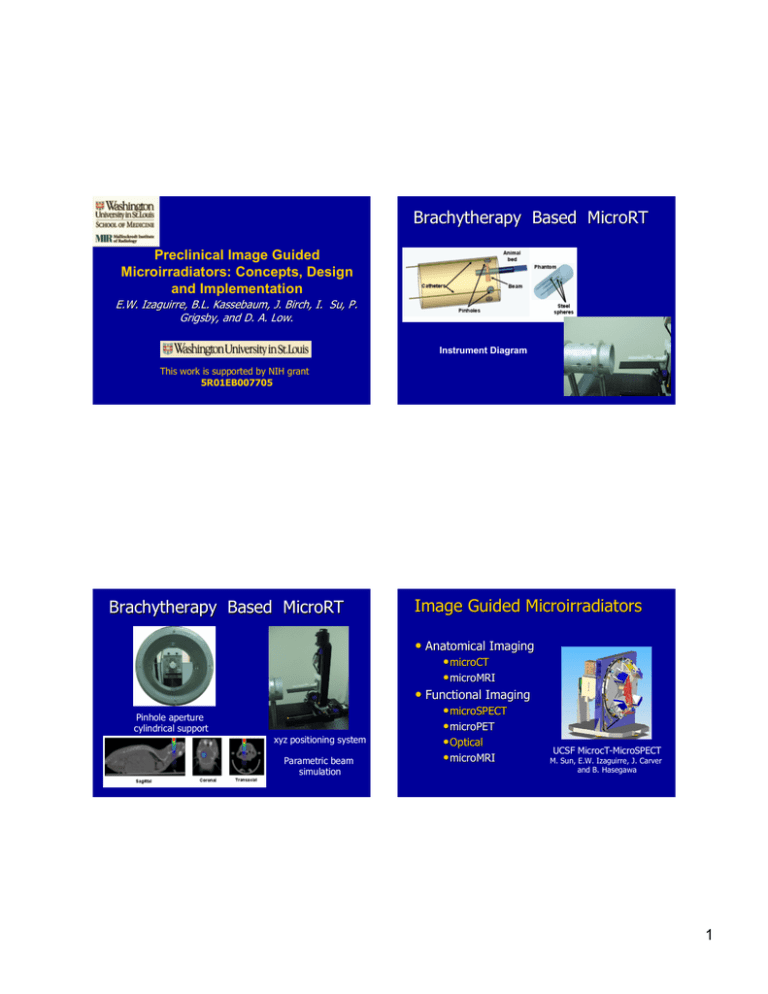
Brachytherapy Based MicroRT Image Guided Microirradiators
advertisement

Brachytherapy Based MicroRT Preclinical Image Guided Microirradiators: Concepts, Design and Implementation E.W. Izaguirre, B.L. Kassebaum, J. Birch, I. Su, P. Grigsby, and D. A. Low. Instrument Diagram This work is supported by NIH grant 5R01EB007705 Brachytherapy Based MicroRT Image Guided Microirradiators • Anatomical Imaging • microCT • microMRI • Functional Imaging Pinhole aperture cylindrical support xyz positioning system Parametric beam simulation • microSPECT • microPET • Optical • microMRI UCSF MicrocT-MicroSPECT M. Sun, E.W. Izaguirre, J. Carver and B. Hasegawa 1 Background Current commercial small animal imaging instrumentation : microCT, microMRI, microPET, microSPECT, and optical scanners. >50% of cancer patients receive radiation therapy. MicroCT + MicroRT = MicroIGRT MicroCT The development of small animal micro irradiation technology has not reached the sophistication of small animal imaging instrumentation. Highly conformal microirradiators with an on board anatomical imaging subsystem should be developed to foster preclinical radiobiology research. MicroRT New instrumentation should provide a state of the art platform and to perform experiments that cannot be performed with the current irradiator technology. MicroIGRT Instrument Overview MicroIGRT Instrument Overview MicroCT MicroRT The designed micro image guided radio therapy (microIGRT) system showing the primary components. The instrument is designed in a tandem configuration where the animal bed is located in the microCT field of view for anatomical imaging and is then shifted to the micro irradiator subsystem for conformal irradiation. The Washington University Image guided Micro Irradiator (MicroIGRT) The microirradiator subsystem consists of a high power orthovoltage source with a high dissipation anode to achieve a small focal spot source capable of delivering high dose rates, percentage depth dose, and submillimeter beam penumbra to small animals. 2 MicroIGRT : Design • Study the feasibility of using industrial orthovoltage sources to deliver accurate dose distributions to radiobiological animal models. • Determine the best commercial orthovoltage source to achieve the following target values : Dose Delivery Accuracy : 5 % Dose Rate : 400400-4000 cGy minmin-1 Dose Homogeneity :5 % Penumbra : 0.25 mm (90%(90%-10%) Positioning Accuracy : 0.25 mm Throughput :10 to 20 min/subject • Develop an accurate treatment planning system with a realistic model model of the selected orthovoltage source. Source Filament Model Filament Input Power Filament Electron Current Orthovoltage Source Simulator Code Flow Diagram Input Filament Power Afil, ∆Vfil Tube kVp Tube mA Tube msec The othtovoltage source simulation program was developed using Visual C++. The code is fully compatible with DSP development tools for hardware/software optimization Source Filament model Anode Emission model Output Beam Model Spectrum I(E), N(E), Itot Animal Phantom model Output Animal dose Anode Emission Model Photon Emission Differential Cross Section Bremsstrahlung Intensity Emitted Photons per Interval of Energy 3 Anode Emission Model Anode Focal Spot Analysis Fraction of Photons Exiting the Anode Electron Penetration Distance Anode Focal Spot Anode Mass Stopping Power Anode Focal Spot Contour Level Map Mass Attenuation Coefficient Bremsstrahlung Coefficient Anode Line Profile Othovoltage Source Spectrum I(A.U.) Anode Focal Spot: Simulation Anode Line Profile Measured anode focal spot Energy (keV) Anode Emission Parameterization Simulated Anode Focal Spot The emission is modulated with the empirical intensity parameterization Spectrum emitted from an arbitrary anode point Simulated anode focal spot 4 Beam Penumbra Simulations Filtering Source Collimator Beam Cross Section Beam Width: 2x2 mm2 Average Penumbra 0.25 mm Beam Profile Collimator: 7 mm Tungsten In order to reduce bone dose we propose to filter the radiation beam. Solid line (blue) unfiltered output, doted line (red) filtered output and dash line (black) bone f-factor. In our proposed filter most of the filtered beam spectrum lies above 150 keV, where the bone f-factor is within 10% of the muscle f-factor. Energy fluence (a.u.) Orthovoltage Source Spectrum Total Body Irradiation Unfiltered Filtered Energy (keV) Simulation of the 320kVp x-ray source without additional filtration and with a filter composed of 1.5 mm Lead, 5 mm Tin, 1 mm Copper, and 4 mm Aluminum. This filter removes the low energy x-ray components to raise the average bremsstrahlung energy to 4.6 mm of Cu. Unfiltered dose profile (red line) and filtered dose profile (green line). Unfiltered Filtered Absorbed Dose Profile Dose rates of 16 Gy/min (filtered) and 40 Gy/min (unfiltered) can be delivered to an animal phantom if the source is operated at 1.5 mA. The maximum source current is 5 mA at the maximum voltage bias, so even greater dose rates will be possible. Animal Phantom: Modified MOBY, John Hopkins Univ. 5 The MicroIGRT . The 3D diagram shows the instrument tandem architecture. Each subsystem can be independently operated. The MicroRT Subsystem The microRT gantry linear translation stages to support the orthovoltage source The MicroRT Subsystem The MicroRT gantry showing the orthovoltage source, the collimation system, and primary beam shielding cup. The MicroRT Subsystem The microRT gantry showing the 320 kVp orthovoltage source mounted on a rotating and a linear stages. Source distance to axis 6” to 12”. 6 The MicroRT Subsystem The microRT primary beam shielding. The lead shield is located on the opposite side of the gantry to compensate the high torque produced by the orthovoltage source weight. The MicroRT Subsystem The MicroRT Subsystem The microRT bearing system for accurate gantry rotation. Rotation precision: 2 arc min. The MicroRT Subsystem Source rotation system Design Gantry rotation system Implementation HV generator Beam stopper + Mouse bed 7 The Micro CT Subsystem The MicroIGRT Beam Diam. 4 mm Image of the Instrument - June 2008 Beam profile The Micro CT Subsystem The microCT bearing system for accurate gantry rotation. Rot precision: 2 arc min. MicroCT gantry showing the flat panel detector and the microfocus x-ray source The Micro CT Subsystem The microCT gantry plate. The gantry is constructed using hollow beams for light weigh and high rigidity 8 The Micro CT Subsystem The microCT gantry showing the four high precision linear stages for imaging instrumentation radial positioning The MicroCT Micro Focus Source The micro focus source collimator. The source is collimated to limit the beam scattering and unnecessary irradiation to non-imaged portions of the animal body The MicroCT Micro Focus Source The micro focus source of the microCT subsystem. Source characteristics: tube potential 80 kVp, tube current 0.5mA, focal spot 75x75um2, and beam divergence 30o. The MicroCT Micro Focus Source The micro focus source shutter. A high speed rotary solenoid is used to shut on and off the beam between exposures 9 The MicroCT Micro Focus Source The micro focus source multiple filter system. The microCT is optimized to acquire high contrast low dose tomographic images of small rodents. The Micro CT Subsystem Complete microCT subsystem with the animal bed The combined circular motion of the gantry with the linear motion of the couch allows circular and helical tomographic scanning The Micro CT Design Implementation The Micro CT Subsystem Rotation gear Cable collection belt 10 The MicroCT Subsystem MicroIGRT • micro-focus 80kVp x-ray source • Focal Spot 75x75 mm2 focal spot • Flat panel amorphous silicon Design detector with 1024x1024 pixels. • High efficiency CsI(Tl) scintillator. • High precision gantry rotation ( 1/60 deg, 0.0001 axis tilt) • Micrometric source and detector positioning (50 mm) • microCT spatial resolution ~ 120 • Implementation mm Dose less than 1cGy/scan. Instrumentation Software Treatment Planning Software Source model Mouse Phantom Pencil Beam Monte Carlo Software Platform : Visual C++ (Microsoft) + National Instruments drivers + In house developed drivers 11 Mouse Bed and Animal Handling Shielding ? • Gas Anesthesia: Isoflurane • Temperature control : IR lamp heater • Respiratory motion sensors • Gas flow sensors Shielding panels construction Al Box frame Al Pb Brachytherapy Based MicroRT Instrument Diagram Brachytherapy MicroRT Previous pinhole New pinhole 2 months Time 3 months 4 months 12 Sensitization of Orthotopic Glioblastomas to Radiotherapy by Transglutaminase 2 Inhibitors List of Collaborative Projects • MRI imaging of necrosis induced by ionizing radiation J. Garbow • Extracellular matrix and Sensitization of orthotopic glioblastomas to radiotherapy by Transglutaminase 2 inhibitors K. Rich 1.25 1.2 • PET tracers to optimize tumor treatment in 1.15 xenograph models of breast cancer: K. Shoghi- 1.1 1.05 1 Radiation Only 0.95 Radiation & Drug 30 20 20 ionizing irradiation. P. Grigsby, M. Taylor, A. Ja n Ja n • Variations in cancer cell motility induced by -J an -J an -J an 20 Ja n rt D ate 27 23 20 0.9 Sta Optical Imaging Jadid Control Ja n Tumor Size (Log of Avg Change in Bioluminescence) . Average Fold Change of Tumor Size in Individual Mice Laszlo and E. Izaguirre Collaboration with Dr Keith Rich , Neurosurgery , WU Multiple Beam Conformal Irradiation Results and Conclusions • We are constructing a small animal imaged guided micro irradiator irradiator which consist in a microRT subsystem integrated with an on board microCT subsystem. • Simulated microCT reconstructed tomographic data demonstrates that that a resolution of 120 µm is achievable using 128 projections and a maximum radiation dose dose of 1cGy. • Automatic animal positioning and handling could be performed within within a precision of 100 µm. The treatment beam can be aimed at different latitude and longitude longitude angles in steps of 2 arc min. and translated at 50µ 50µm steps (x,y,z). The beam cross section can be modulated with submillimeter precision using steps of 50 µm . • We determined that a source of nominal maximum potential output of 320kVp and Mouse phantom Liver phantom Mask generation using back propagation focal spot of 0.4x0.4 mm2 outperformed other available sources. We designed a ThoraeusThoraeus-like filter to obtain a bremsstrahlung spectrum energy greater than 4mm of Cu to increase skin spare and reduce bone dose. Collimator exchange • An average beam penumbra of 0.25mm and a dose rate of 16 Gy/min Gy/min is possible using this filtered beam. Higher energy sources would increase cost and shielding thickness. Lower energies sources showed limited intensities when when they were aggressively filtered. • The construction of the device will be finished shortly. The commissioning commissioning of the complete system is expected by the end of this year Multiple beam irradiation 13 Collaborators Daniel Low Jeff Michalski Marie Taylor Robert Myerson Sasa Mutic Paraq Parikh Perry Grigsby Keith Rich Joseph Deasy Joel Garbow Kooresh Shoghi Sreekrishna M Goddu Jose Garcia Ramirez Dharanipathy Rangaraj Joseph Roti Roti D. Hallahan Andrei Laszlo Buck Rogers Suzana Gonzalo Ilona Fleischer Acknowledgments Laboratory Members Bethany Kassebaum Xiumin Diao Jordan Birch I-Tan Su Animal Phantom John Hopkins Univ. Paul Segars Thank you ! We are looking for a postdoc !!! Benhamin Tsui High Resolution Low Dose MicroCT Current Imaging of Tumor Vasculature - Techniques to image tumor vasculature are based in multiple micro CT images (8 frames /view). -Unnecessary high dose delivered to the animal Kindlmann et al. New technique: Low dose micro CT - High efficiency detectors for small animal: 80kVp -The only option is to change the scintillator -Dual energy microCT Study of the Tumor Micro Environment Goals of the project : Imaging angiogenesis Determine vascular renormalization induced during treatment Correlate tumor vascularity with oxygen distribution 14 Dual Energy MicroCT X-ray Source Spectrum Dual energy simulations 15


