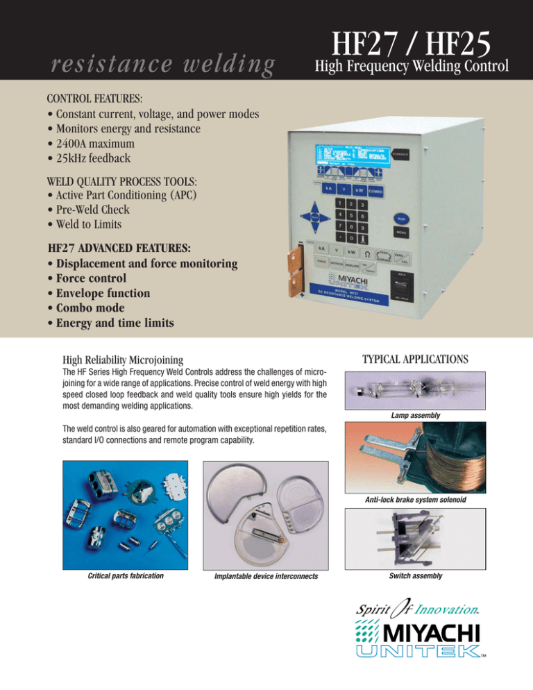
resistance welding
HF27
/
HF25
High Frequency Welding Control
CONTROL FEATURES:
• Constant current, voltage, and power modes
• Monitors energy and resistance
• 2400A maximum
• 25kHz feedback
WELD QUALITY PROCESS TOOLS:
• Active Part Conditioning (APC)
• Pre-Weld Check
• Weld to Limits
HF27 ADVANCED FEATURES:
• Displacement and force monitoring
• Force control
• Envelope function
• Combo mode
• Energy and time limits
TYPICAL APPLICATIONS
High Reliability Microjoining
The HF Series High Frequency Weld Controls address the challenges of microjoining for a wide range of applications. Precise control of weld energy with high
speed closed loop feedback and weld quality tools ensure high yields for the
most demanding welding applications.
Lamp assembly
The weld control is also geared for automation with exceptional repetition rates,
standard I/O connections and remote program capability.
Anti-lock brake system solenoid
Critical parts fabrication
Implantable device interconnects
Switch assembly
Intuitive, Easy-to-Use
Programming
Current, Voltage and Power
Feedback Modes:
Constant Voltage:
• Intuitive graphical user interface.
• Dual pulse waveforms programmed in current,
voltage, or power control modes.
• Programming times to 100 µ sec increments
provides ultimate control.
• Accurate, built-in monitor displays the graphical
“trace” of weld current, voltage, power and
resistance, along with numerical peak and
average values.
• Easy-to-set limits establish process window
for acceptable quality.
• User programmable relays can be used in
conjunction with visual and audible signals for
operators and automation interface.
• Compensates for parts misplacement and force
problems
• Reduces weld splash
• ideal for round (non-flat) parts
Monitor current
Constant Power:
• Varies current and voltage for consistent energy
• Breaks up surface oxides and plating
• Ideal for automation to extend electrode life
Monitor current or voltage
Constant Current:
• Delivers same current regardless of resistance
changes
• Compensates for part thickness changes
• Ideal for flat parts with consistent electrode to
part fit-up
Monitor voltage
Effective Weld Monitoring and Process Tools
Pre-Weld Function
Active Part Conditioner (APC)
Weld Stop
Run Screen – Shows that 2nd Pulse was inhibited from firing.
Run Screen – Constant power first pulse breaks through oxides.
Run Screen – Shows termination of weld current during weld pulse.
Monitor Screen – Shows 1st Pulse weld voltage exceeded limit.
Monitor Screen – First pulse time automatically compensates
for varying levels of oxides.
Monitor Screen – Shows weld voltage exceeding limit.
Sends an initial short, low energy pulse through
the assembly, tests key electrical parameters
against pre-set limits, and inhibits operation if
limits are exceeded.
First pulse adapts weld time to displace oxides
then terminates allowing a second pulse with
upslope to complete the weld, thus avoiding
weld splash.
Terminates the weld energy during the welding
process if pre-set weld current or voltage
limits are exceeded.
Advantages
Advantages
• Prevents unacceptable welds.
• Brings each part to the same resistance prior
to application of welding current.
• Prevents electrode damage.
• Alerts operator to weld fault.
• Relay outputs can signal automation.
• Provides for consistent welding of difficultto-weld oxidized parts.
• Prevents weld splash.
• Increases process yields.
Advantages
• Prevents blow-outs and parts damage.
• Prevents electrode damage.
• Alerts operator to weld fault.
• Relay outputs can signal automation.
HF27’s Advanced Process Features
A New Generation of Weld Control Precisely Controls and Monitors Electrical and Mechanical Weld Parameters.
Displacement
• Initial Thickness (Part Detection)
• Final Thickness
• Weld Displacement (Set Down)
• Energy Stop (Weld to Limit)
LVDT Screen – Program limits and view results.
Measurement of initial part thickness can
confirm parts are present and aligned for
welding. Settings limits on the mechanical
displacement can confirm the electrical
parameters have produced the correct
part displacement and can also prove a
good indication of weld quality.
LVDT provides vital process data.
Program relay outputs to signal automation.
Envelope
The Envelope Limits enables upper and lower limits to be placed around
an optimized weld signature. Any deviation across the envelope results
in an alarm, and a specified action. This feature can detect even slight
changes in the process that could lead to inconsistent welds. This high
level of verification is preferred in many medical device and automotive
welding applications, which must meet strict process control and
quality requirements.
Advanced Control Modes
Force Control is accomplished using a proportional valve to set the air
pressure on a pneumatic weld head. Force settings are schedule dependent,
matched to different applications. Force Control can increase production rates
by reducing down time and improving cycle times in automated systems.
The Force Monitor through a weld head mounted load cell eliminates the
time consuming task of repeatedly verifying electrode forces on production
lines with multiple welding stations.
The Combo Function allows a weld to be initiated in voltage or power
mode, then switch to constant current when a preset limit is reached. The
combo mode can reduce the occurrence of weld splash and over-melting
of the parts. Typical applications for the Combo Mode include wire welds,
tang welds, and motor fusing.
Expanded Monitoring Options
The Weld Energy Monitor calculates the energy in Joules that is delivered
to each weld. This feature indicates changes in weld energy, and is
typically implemented for operator dependent, manual welding stations
where part fit-up can vary.
Time limits can be programmed when welding to displacement or
electrical limits. Monitoring the actual weld time can ensure consistency,
adding an additional safety net to the weld process.
SPECIFICATIONS
Model Number
HF25/240
HF25/400
HF25/480
HF27/240
HF27/400
HF27/480
Nominal Line Voltage (3 phase)
240 VAC
400 VAC
480 VAC
240 VAC
400 VAC
480 VAC
Line Voltage Range (VAC)
192 to 264
320 to 440
384 to 528
192 to 264
320 to 440
384 to 528
Input Circuit Rating (per phase)
25A
20A
13A
25A
20A
13A
Input KVA @ 3% duty cycle
30KVA
Output KW @ Max. demand
12KW
Output Transformer Voltage @ Max. Rated Output Current
5.2V
Open Circuit Max. Output Voltage @ Nominal Line
11.5V
Setting Ranges
Current – 100A to 2400A; Voltage – 0.2V to 10V; Power – 50W to 10kW
Output Current
2400A @ 3% duty cycle
Output Feedback Response Time (Current, Voltage, Power)
40 Microseconds
Output Regulation versus Line Voltage Variance
2%
Output Regulation versus Load Resistance Variance
2%
Output Repeatability Current, Voltage, Power ± of Setting
2%
Weld Period Ranges
All segments except squeeze and hold 0.10ms to 10ms, 0.1ms steps; 10 to 99ms, 1ms steps; squeeze and hold 0 to 999ms, 1ms steps
Weld Energy Setting Accuracy
Current: 2% of setting or 2A, whichever is greater; Voltage: 2% of setting or 0.050V, whichever is greater; Power: 5% of setting or 20W, whichever is greater
FEATURES
Weld Heat Profile Functions
Weld Pulse Control
Programmable Weld Pulse Segments
Weld Schedule Memory
Measurement Parameters
Graphic Display
Measurement Selection
Current Measurement Range/Accuracy
Voltage Measurement Range/Accuracy
Power Measurement Range/Accuracy
Alarms
Programmable Weld Energy Limit
Weld Pre-Check
Active Part Conditioner
Dual pulse with independent control of current, voltage, power or combo mode (HF27) on each pulse.
Squeeze, upslope 1, weld 1, downslope 1, cool, upslope 2, weld 2, downslope 2, hold.
Save up to 100 different weld schedules, protected from unauthorized changes.
Independent monitor of current, voltage, power, and resistance on each pulse. Envelope, time limits and energy monitor (HF27).
Back-lit LCD displays programmed and actual weld current, voltage or power, upper and lower limits, and resistance.
Peak or average
50.0A to 2.400KA/±2% of reading or ±2A, whichever is greater.
0.2V to 9.999V/±2% of reading or ±0.05V, whichever is greater.
0.01KW to 9.999KW/±5% of reading or ±20W, whichever is greater.
Display alert, four user programmable AC/DC relays; audio alarm.
Terminates weld energy when exceeding user defined current, voltage, or power limits.
Inhibit second weld pulse when first test pulse exceeds user programmed limits.
First pulse current limit in constant power allows second pulse to fire.
I/O and Data Communications
Input
Input Isolation
Control Voltages
Firing Switch Initiation
Remote Control
RS232
RS485
Electrode Voltage
Weld Head Air Valve Driver
Alarm Relays
All inputs and outputs are fully isolated.
Selectable: +5V, +24V, sourcing or sinking inputs.
1-level foot switch, 2-level foot switch, mechanical or opto firing switch.
Remote weld schedule select, process inhibit, emergency stop.
Change weld schedules and individual parameters.
Change weld schedules and individual weld parameters; “Daisy Chain” unit to unit, unit(s) to host computer.
Weld voltage signal for voltage feedback operation (0 to 10V peak).
24 VAC, 1A; timing controlled by HF25/HF27. Operates new EZ-Air.
Four user-programmable mechanical relays; programmable normally open or normally closed; contacts:
250 VAC at 5 A; 30 VDC at 5 A. Conditions: weld, end of weld, alarm, out of limits.
Displacement Option (HF27 only)
Capabilities
Accuracy of Displacement Readings Inches (mm)
Repeatability
Maximum Travel Inches (mm)
Alarm Relays
Data Output
80DSPK
Part detection, final thickness measurement, set down measurement, energy stop (weld to limit)
± .003 (0.076)
± 1.0 %
1 (25)
Additional conditions: Any LVDT, initial Lo/Hi, final Lo/Hi, displacement Lo/Hi, initial NG, displacement NG, energy stop
Initial thickness, final thickness, displacement, and any alarm condition
Attaches to Miyachi Unitek Series 80 weld heads. Includes LVDT, interface cable, and mount
Force Control and Monitor (HF27 only)
Force Input
Force Measurement
Force Output
Force Programming
0-10V input signal from signal conditioner or load cell
End of squeeze, end of hold
0-10V for use with proportional valve
lbs, kg. N. force can be stored b schedule
Physical Characteristics
Dimensions (L x W x H) Inches (mm)
Weight – Lbs (Kg)
18 x 9 x 12.8 (460 x 230 x 325)
54 (25)
ACCESSORIES ORDERING GUIDE
Included Accessories
Required Accessories
Optional Accessories
All models listed above include: Control weld cable bolts, rear panel Phoenix connectors, voltage sense cable, manual, CE safety sheet.
Weld head; Foot switch or Foot Pedal.
Microscope. Built-in displacement option on HF27 includes software, requires LVDT, interface cable, and mount for Series 80 weld head (P/N 80DSPK).
Load cell and proportional valve per specific weld head model.
Your Local Representative
Specifications subject to change without notice.
Copyright© 2006 Miyachi Unitek Corporation. The material contained herein cannot
be reproduced or used in any other way without the express written permission of
Miyachi Unitek Corporation. All rights reserved.
EASTERN (USA) Sales Office:
170 Cross Street
Boylston, MA 01505
Tel: (508) 869-0583
FAX: (508) 869-0585
E-Mail: eastsales@miyachiunitek.com
ASIA Sales Office:
Unit D, 20/F, Infotech Centre
21 Hung To Road
Kwun Tong, Hong Kong
Tel: +852 2833-6998
FAX: +852 2833-6672
E-Mail: asiapacific@miyachiunitek.com
UNITEK EAPRO:
Schootense Dreef 21
NL-5708 HZ Helmond
The Netherlands
Tel: +31 492-54-22-25
FAX: +31 492-53-62-22
E-Mail: info@unitekeapro.com
991-009 11/06
Corporate Office: 1820 S. Myrtle Ave. • P.O. Box 5033 • Monrovia, CA 91017-7133 USA
Tel: (626) 303-5676 • FAX: (626) 358-8048 • E-Mail: info@miyachiunitek.com
Internet http://www.miyachiunitek.com • ISO 9001 Certified Company


