Trajectory Planning and Control of an Underactuated Dynamically
advertisement
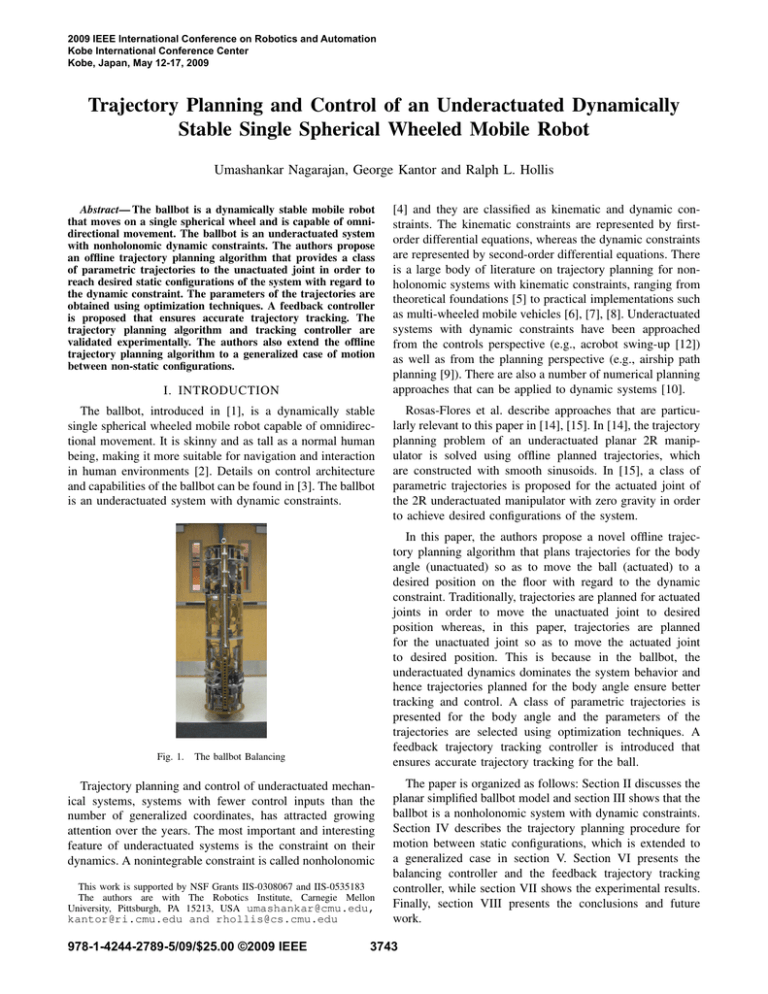
2009 IEEE International Conference on Robotics and Automation Kobe International Conference Center Kobe, Japan, May 12-17, 2009 Trajectory Planning and Control of an Underactuated Dynamically Stable Single Spherical Wheeled Mobile Robot Umashankar Nagarajan, George Kantor and Ralph L. Hollis Abstract— The ballbot is a dynamically stable mobile robot that moves on a single spherical wheel and is capable of omnidirectional movement. The ballbot is an underactuated system with nonholonomic dynamic constraints. The authors propose an offline trajectory planning algorithm that provides a class of parametric trajectories to the unactuated joint in order to reach desired static configurations of the system with regard to the dynamic constraint. The parameters of the trajectories are obtained using optimization techniques. A feedback controller is proposed that ensures accurate trajectory tracking. The trajectory planning algorithm and tracking controller are validated experimentally. The authors also extend the offline trajectory planning algorithm to a generalized case of motion between non-static configurations. I. INTRODUCTION The ballbot, introduced in [1], is a dynamically stable single spherical wheeled mobile robot capable of omnidirectional movement. It is skinny and as tall as a normal human being, making it more suitable for navigation and interaction in human environments [2]. Details on control architecture and capabilities of the ballbot can be found in [3]. The ballbot is an underactuated system with dynamic constraints. Fig. 1. Trajectory planning and control of underactuated mechanical systems, systems with fewer control inputs than the number of generalized coordinates, has attracted growing attention over the years. The most important and interesting feature of underactuated systems is the constraint on their dynamics. A nonintegrable constraint is called nonholonomic This work is supported by NSF Grants IIS-0308067 and IIS-0535183 The authors are with The Robotics Institute, Carnegie Mellon University, Pittsburgh, PA 15213, USA umashankar@cmu.edu, 978-1-4244-2789-5/09/$25.00 ©2009 IEEE Rosas-Flores et al. describe approaches that are particularly relevant to this paper in [14], [15]. In [14], the trajectory planning problem of an underactuated planar 2R manipulator is solved using offline planned trajectories, which are constructed with smooth sinusoids. In [15], a class of parametric trajectories is proposed for the actuated joint of the 2R underactuated manipulator with zero gravity in order to achieve desired configurations of the system. In this paper, the authors propose a novel offline trajectory planning algorithm that plans trajectories for the body angle (unactuated) so as to move the ball (actuated) to a desired position on the floor with regard to the dynamic constraint. Traditionally, trajectories are planned for actuated joints in order to move the unactuated joint to desired position whereas, in this paper, trajectories are planned for the unactuated joint so as to move the actuated joint to desired position. This is because in the ballbot, the underactuated dynamics dominates the system behavior and hence trajectories planned for the body angle ensure better tracking and control. A class of parametric trajectories is presented for the body angle and the parameters of the trajectories are selected using optimization techniques. A feedback trajectory tracking controller is introduced that ensures accurate trajectory tracking for the ball. The ballbot Balancing kantor@ri.cmu.edu and rhollis@cs.cmu.edu [4] and they are classified as kinematic and dynamic constraints. The kinematic constraints are represented by firstorder differential equations, whereas the dynamic constraints are represented by second-order differential equations. There is a large body of literature on trajectory planning for nonholonomic systems with kinematic constraints, ranging from theoretical foundations [5] to practical implementations such as multi-wheeled mobile vehicles [6], [7], [8]. Underactuated systems with dynamic constraints have been approached from the controls perspective (e.g., acrobot swing-up [12]) as well as from the planning perspective (e.g., airship path planning [9]). There are also a number of numerical planning approaches that can be applied to dynamic systems [10]. The paper is organized as follows: Section II discusses the planar simplified ballbot model and section III shows that the ballbot is a nonholonomic system with dynamic constraints. Section IV describes the trajectory planning procedure for motion between static configurations, which is extended to a generalized case in section V. Section VI presents the balancing controller and the feedback trajectory tracking controller, while section VII shows the experimental results. Finally, section VIII presents the conclusions and future work. 3743 II. PLANAR SIMPLIFIED BALLBOT MODEL The ballbot is modeled as a rigid cylinder on top of a rigid sphere. A planar model of the ballbot is used for developing the trajectory planner. The following assumptions are made in the model: (i) there is no slip between the spherical wheel and the floor, (ii) the motion in the median sagital plane and median coronal plane is decoupled, and (iii) the equations of motion in these two planes are identical. With these assumptions, we can design two decoupled, independent planar trajectory planners for the 3D system. where α = Iball + (mball + mbody )r2 , β = mbody rℓ, γ = Ibody + mbody ℓ2 , Dc and Dv are the coulomb friction and the viscous damping friction terms respectively. Please refer to Table I for the other symbols. Eq. 1 can be re-written as follows: τ Ma q̈a Ca Ga Da (6) = + + + 0 Mu q̈u Cu Gu 0 where qa = θ represents the actuated joint and qu = φ represents the unactuated joint. The dynamic equation corresponding to the unactuated joint is: Mu (q)q̈ +Cu (q, q̇) + Gu (q) = 0. (7) III. INTEGRABILITY OF CONSTRAINTS mbody l r Fig. 2. Planar Simplified Ballbot Model Euler-Lagrange equations are used to derive the dynamic equations of motion of the planar ballbot model1 shown in Fig. 2. The angle between the body and the vertical is referred as the body angle φ , while the angle between the ball and the body is referred as the ball angle θ . The equations of motion for the simplified planar ballbot model can be written in matrix form as follows: τ , (1) M(q)q̈ +C(q, q̇) + G(q) + D(q̇) = 0 where q = [θ , φ ]T is the generalized coordinate vector, M(q) is the mass/inertia matrix, C(q, q̇) is the vector of coriolis and centrifugal forces, G(q) is the vector of gravitational forces, D(q̇) is the frictional torque vector and τ is the torque applied between the ball and the body in the direction normal to the plane. The expressions for the above mentioned terms are given below: α α + β cos φ , (2) M(q) = α + β cos φ α + γ + 2β cos φ −β sin φ φ̇ 2 C(q, q̇) = , (3) −β sin φ φ̇ 2 0 , (4) G(q) = φ − β g sin r Dc sgn(θ̇ ) + Dv θ̇ D(q̇) = , (5) 0 1 It is to be noted that the model described below uses a coordinate scheme different from the one described in [2]. The ballbot is an underactuated robot as there is no direct actuation on the body angle φ . Eq. 7 may be interpreted as a constraint involving generalized coordinates as well as their first and second-order time derivatives. It is important to determine if this constraint is integrable or not. If it is completely integrable, we would obtain an algebraic relation between the generalized coordinates. The conditions for partial and complete integrability are given below. With reference to [16], the constraint in Eq. 7 is: 1) partially integrable if and only if: a) the gravitational torque Gu is constant; b) the unactuated joint variables φ do not appear in the inertia matrix M(q). 2) completely integrable (holonomic) if and only if: a) it is partially integrable; b) the distribution ∆ defined by (Mu (q)q̇ = 0) is involutive. From Eq. 2 and Eq. 4, it is clear that the gravitational torque Gu (q) is not a constant and the unactuated joint variables φ do appear in the inertia matrix M(q). This implies that the constraint shown in Eq. 7 is not partially integrable which makes it not completely integrable. Therefore, we conclude that the unactuated joint dynamics form a nonholonomic dynamic constraint. This dynamic constraint plays an important role in planning trajectories that can make the underactuated system navigate to desired configurations. IV. TRAJECTORY PLANNING BETWEEN STATIC CONFIGURATIONS Trajectory planning for motion from an initial configuration to a desired final configuration is an important feature of any mobile robot. For dynamically stable mobile robots like the ballbot, the trajectory planning problem is complicated by the fact that the planned trajectory must respect the dynamic constraint. The dynamic constraint given by Eq. 7 can be re-written of the form: θ̈ = = f (φ , φ̇ , φ̈ ) β g/r sin φ + β sin φ φ̇ 2 − (α + γ + 2β cos φ )φ̈ . (8) α + β cos φ This indicates that in order to stick to a constant nonzero desired body angle φd (φ̇d = 0 and φ̈d = 0), the ball 3744 has to accelerate. This also indicates that it is possible to generate a body angle trajectory that will move the ball to a desired position. Given the desired initial and final ball angular positions θd0 and θd f , if θ (t0 ) = θd0 , then one can find t f ∈ ℜ and φ (t) for t∈ [t0 ,t f ] such that the resulting trajectory satisfies θ (t f ) = θd f . It is to be noted that θd0 and θd f correspond to the motion on the floor. A class of parametric trajectories is proposed for the body angle to make the ballbot move from a static initial configuration to a static final configuration. The parameters of the proposed trajectories depend on the initial and final desired configurations. It is to be noted that for the ballbot to move forward and come to rest, the body has to lean forward first and then lean back to stop (Fig. 3(a)). With this physical understanding of system behavior, we follow [15] to propose the following trajectory for the body angle: 2t − t f − tm 2t − tm − t0 ) + φ pa2 sech(k ), tm − t0 t f − tm (9) where φ pa1 , φ pa2 are the amplitudes of the hyperbolic secant functions, tm = (t0 +t f )/2 and k = 9 is a constant scalar. The constant scalar k determines the width of the peak given the other parameters. Given φ pa1 , φ pa2 , t0 and t f , a smaller k value results in a wider peak, whereas, a larger k value results in a narrower peak. It is to be noted that in [15], the above mentioned parametric trajectory was used for the actuated joint and here, the authors use the same for the unactuated joint. The trajectory φ p (t) depends on three parameters φ pa1 , φ pa2 and t f . The three parameters, φ pa1 , φ pa2 and t f , are to be determined such that when the ballbot tracks the body angle trajectory φ p (t), the ball comes to rest at the desired final position θd f . Trajectory optimization is used to select suitable parameter values. The trajectory planning problem can be formulated into an optimization problem as follows: The path connecting the initial configuration (θ (t0 ), φ (t0 )) = (θd0 , 0) with (θ̇ (t0 ), φ̇ (t0 )) = (0, 0) to the final configuration (θ (t f ), φ (t f )) = (θd f , 0) with (θ̇ (t f ), φ̇ (t f )) = (0, 0) can be determined by choosing the parameters φ pa1 , φ pa2 and t f such that the objective function: and φ pa2 . Since we wish to optimize over time and control effort, the final time t f is also used as a free parameter to be optimized for. We use the Nelder-Mead simplex method [17] for trajectory optimization. The optimization procedure starts with given initial parameters for φ pa1 , φ pa2 and t f , computes the objective function J (Eq. 10) and checks for a minimum. If the objective function is not a minimum, the algorithm proceeds to determine new parameters and loops until it finds a minimum. The planned trajectory for the body angle φ p (t) is obtained by using the parameters from optimization in Eq. 9. The planned trajectory for the ball angle θ p (t) can be determined by solving the dynamic constraint (Eq. 11) by using φ p (t), φ̇ p (t) and φ̈ p (t). It is to be noted that the parameters obtained by the optimization process depend on the initial parameter values. φ p (t) = φ pa1 sech(k J = w1 (θ (t f ) − θd f )2 + w2 θ̇ 2 (t f ) + Z tf 0 (w3t + w4 τ 2 )dt (10) has a minimum subject to the dynamic constraint from Eq. 8: (α + β cos φ p )θ̈ + (α + γ + 2β cos φ p )φ̈ p β g sin φ p −β sin φ p φ̇ p2 − r = 0. (11) The constraints θ (t f ) = θd f and θ̇ (t f ) = 0, which ensure that the ball has reached its final static position, are enforced by choosing large weights w1 and w2 in the objective function (Eq. 10). The weights w3 and w4 are chosen to weight the relative cost between time and control effort. The constraints φ (t f ) = 0 and φ̇ (t f ) = 0 are not explicitly mentioned in Eq. 11 as they are automatically satisfied when φ tracks φ p (t). It is possible to fix t f and just determine the parameters φ pa1 (a) Static-Static case Fig. 3. (b) Generalized case Proposed parametric trajectories for body angle V. GENERALIZED TRAJECTORY PLANNING A trajectory planning algorithm that moves the ballbot from an initial static configuration to a desired final static configuration was presented in Section IV. In a more general case, the ballbot should be capable of moving between non-static configurations allowing piecewise continuous trajectories to be planned. The trajectory planning algorithm presented in Section IV can be extended to a generalized case. Given the desired initial and final ball angular positions and velocities (θd0 , θd f , θ̇d0 and θ̇d f ) and the initial body angular position and velocity (φ0 and φ̇0 ), if θ (t0 ) = θd0 , θ̇ (t0 ) = θ̇d0 , φ (t0 ) = φ0 and φ̇ (t0 ) = φ̇0 , then one can find φ f , φ̇ f ,t f ∈ ℜ and φ (t) for t∈ [t0 ,t f ] such that the resulting trajectory satisfies θ (t f ) = θd f , θ̇ (t f ) = θ̇d f , φ (t f ) = φ f and φ̇ (t f ) = φ̇ f . The new proposed parametric trajectory for the body angle (Eq. 12), as shown in Fig. 3(b), is written as the sum of the hyperbolic secant trajectories (Eq. 9) and a smooth function, e.g., a cubic spline trajectory. φ p (t) = φ pa1 sech(k 2t − t f − tm 2t − tm − t0 ) + φ pa2 sech(k ) tm − t0 t f − tm + a0 + a1t + a2t 2 + a3t 3 , (12) where φ pa1 , φ pa2 , tm , k are the same as in Eq. 9, while a0 , a1 , a2 and a3 are the cubic spline coefficients determined using t0 ,t f , φ0 , φ̇0 , φ f and φ̇ f . Here, the body angle trajectory φ p (t) depends on five parameters namely, φ pa1 , φ pa2 , t f , φ f and φ̇ f . These five parameters in turn depend on the initial and desired final ball angular positions (θd0 , θd f ) and ball angular velocities (θ̇d0 , θ̇d f ). 3745 For the 3D ballbot system, trajectory planning in the two planes cannot be completely de-coupled. In order to reach a desired configuration on the floor, the time t f must be the same for body angle trajectories in both the planes. So, the generalized trajectory planner implements the trajectory planning algorithm described above for both the planes (say, XZ and YZ planes) simultaneously with a total of nine parameters, namely, φ pax1 , φ pax2 , φx f , φ̇x f , φ pay1 , φ pay2 , φy f , φ̇y f and t f . The objective function for the trajectory optimization is chosen to be: J mass position of the body, ℓ, was determined experimentally (Table I). The controller designed is a Proportional-IntegralDerivative (PID) controller that feeds back the body angle φ . The controller gains were experimentally tuned. Fig. 4. Balancing Controller = (Θ(t f ) − Θd f )T W1 (Θ(t f ) − Θd f ) + (Θ̇(t f ) − Θ̇ f )T W2 (Θ̇(t f ) − Θ̇ f ) + Z tf 0 (w3t + QT W4 Q)dt, (13) where Θ = [θx , θy ]T and Q = [τx , τy ]T . The weight w3 and the elements of the weight matrices W1 , W2 and W4 are chosen as in Eq. 10. The trajectory optimization procedure finds appropriate values for the nine parameters mentioned above such that the objective function J in Eq. 13 has a minimum subject to the constraint in Eq. 11 for trajectories in both the planes. In the special case of reaching a static desired final configuration, the generalized trajectory planner forces φx f , φ̇x f , φy f and φ̇y f to be zero and optimizes over the remaining five parameters. Any arbitrary desired motion of the ballbot on the floor can be characteristized by a collection of desired configurations and the trajectory planning procedure presented can be used to obtain the trajectories that move between the desired configurations. The balancing controller takes the desired body angle as input, which is zero in a pure balancing case and tries to balance about that angle. One can feed in desired angles to the balancing controller to move the ballbot around. The planned body angle trajectory φ p can be fed into the balancing controller which tries to track it. This results in a feedforward trajectory tracking operation as the ball angle θ is not fed back to the controller. The balancing controller eliminates the model uncertainities and performs what the feedforward torque in (Eq. 14) would do if our model was a good representation of the real system. Fig. 5. VI. TRAJECTORY TRACKING CONTROL As per the planar simplified ballbot model (Eq. 1), given φ p (t) and θ p (t), the input torque required to track the trajectories is given by the dynamic equation corresponding to the actuated joint: τ = Ma (q p )q̈ p +Ca (q p , q̇ p ) + Ga (q p ) + Da (q̇ p ), (14) ]T . where q p = [θ p , φ p The open loop control input obtained in Eq. 14 fails on the real robot due to modeling errors, nonlinear friction effects and perturbations. The ballbot has high static friction and unmodeled higher order modes that make the planar simplified model unusable for model based control. So, the authors resort to other control techniques that help track the planned trajectories. A. Balancing Controller The balancing controller for the 3D ballbot system is designed as two independent controllers operating one in each of the vertical planes. The authors draw inspiration from Zero Moment Point (ZMP) based controllers [18] for humanoid robots to design the balancing controller for the ballbot. The balancing controller shown in Fig. 4 attempts at moving the center of the ball to a point directly below the center of mass of the body. The projection of the center of mass of the body on the horizontal plane passing through the center of the ball is given by ℓ sin φ . The center of Trajectory Tracking Feedback Controller B. Feedback Trajectory Tracking Controller A feedforward trajectory tracking operation may not allow the system to reach the desired configuration due to changes in floor conditions, errors in modeling, nonzero initial conditions and other perturbations. A feedback trajectory tracking controller must be designed to guarantee accurate trajectory tracking for the system. The feedback controller is designed as a wrapper around the balancing controller and its control system block diagram is shown in Fig. 5. The ball angle is regulated about the ball trajectory θ p (t) obtained by solving the dynamic constraint (Eq. 11). The feedback trajectory tracking controller is a PID controller that feeds back ball angle θ and outputs a body angle compensation φc depending on whether the ball position is overshooting or falling short from its planned trajectory θ p (t). The gains of the PID controller were experimentally tuned. The body angle compensation is added to the planned trajectory to form the desired trajectory φd (t) (Eq. 15), which the inner balancing PID loop tries to track. The feedback compensation is saturated to avoid large values which might drive the system unstable. 3746 φd (t) = φ p (t) + φc (t). (15) TABLE I S YSTEM PARAMETERS Value (unit) 51.663 (kg) 2.437 (kg) 0.1058 (m) 0.69 (m) 37.1873 (kgm2 ) 0.0174 (kgm2 ) 4.39 (Nm) 0.1772 (Nm/rad/s) 0.5 Desired Experimental 0 −0.5 0 10 Time (s) 0.5 Angle (deg) Parameter Mass of the body Mass of the ball Radius of the ball Center of Mass of the body Moment of Inertia of the body Moment of Inertia of the ball Coulomb Friction Torque Viscous Damping Friction Coefficient Angle (deg) Symbol mbody mball r ℓ Ibody Iball Dc Dv -0.4087◦ and t f = 19.54 s. The planned body angle trajectory and the ball angle trajectory obtained by solving the dynamic constraint are shown in Fig. 6(a) and Fig. 6(b) respectively. Desired Experimental 0 −0.5 0 20 10 Time (s) (a) Roll 20 (b) Pitch 0.5 Fig. 8. Angle (rad) Angle (deg) 10 0 The planned trajectory for the body angle and the desired trajectory for the ball angle are fed into both the planar tracking controllers in order to make the ballbot move from (0 m, 0 m) to (1 m, 1 m) on the floor plane (XY plane). The body angle compensation output from the feedback controller and the desired body angle trajectories (Eq. 15) for roll and pitch angles are shown in Fig. 7(a) and Fig. 7(b) respectively. 5 0 −0.5 0 10 Time (s) 20 0 (a) Body Angle Fig. 6. 5 10 15 Time (s) 20 Experimental trajectory tracking for body angles 25 (b) Ball Angle Planned trajectories for motion between static configurations Angle (rad) A. Experimental Results for Motion between Static Configurations 10 5 Desired Experimental 0 0.5 Planned φ 0.5 p Desired φ d 0 −0.5 0 10 Time (s) (a) Roll 20 Planned φp Compensation φ c Angle (deg) Angle (deg) Compensation φc Desired φd 0 −0.5 0 10 Time (s) 0 5 10 15 Time (s) Fig. 9. 25 5 Desired Experimental 0 0 5 10 15 Time (s) 20 25 (b) Y Ball Angle Experimental trajectory tracking for ball angles Fig. 8(a) and Fig. 8(b) show the balancing controller’s effort to track the desired trajectories for roll and pitch respectively. The seemingly growing instability in the body angles is just an artifact of the close-up view we have on the plot. The balancing controller is capable of balancing about the origin for a long time as shown in [3]. The feedback tracking controller’s effort at tracking the ball angle for the X and Y directions are shown in Fig. 9(a) and Fig. 9(b) respectively. The ballbot’s successful motion from (0 m, 0 m) to (1 m, 1 m) on the floor is shown in Fig. 10. 20 (b) Pitch Fig. 7. Desired body angle trajectories using feedback compensation from experiments on the ballbot Suppose the objective is to move the ballbot one meter from its starting zero position on the floor. This transforms to a motion from an initial configuration (θ0 , φ0 ) = (0 rad, 0 rad) to a final configuration (θ f , φ f ) = (1/r, 0) = (9.45 rad, 0 rad). Starting with a initial parameter set of φ pa1 = 0.35◦ , φ pa2 = -0.35◦ and t f = 15 s, the parameters that minimize the objective function in Eq. 10 are φ pa1 = 0.4062◦ , φ pa2 = 20 (a) X Ball Angle Y Linear Position (m) The trajectory planning and control described in Sections IV & VI-B were implemented on the ballbot. The system parameters like moment of inertia and center of mass were experimentally determined and are tabulated in Table I. The dynamic constraint in Eq. 7 was numerically solved using ode45 in MATLAB and the Nelder-Mead simplex method was implemented using f minsearch in MATLAB. It is important to note that the parameters estimated from the trajectory planning algorithm with recursive optimization depend on the algorithm’s initial parameters. Angle (rad) 10 VII. RESULTS Fig. 10. 1.5 1 0.5 0 −0.5 −0.5 Desired Experimental 0 0.5 1 1.5 X Linear Position (m) Experimental trajectory tracking on the floor B. Initial Results for Generalized Trajectory Planning The initial results of successful trajectory planning between non-static configurations are presented here. Suppose 3747 Final 1 Segment−2 0.5 Segment−1 0 0 Middle Initial Y Linear Position (m) Y Linear Position (m) the objective is to move the ballbot on a circular arc from (0 m, 0 m) to (1 m, 1 m) on the floor from an initial static configuration to a final static configuration (Fig. 11(a)). The trajectory planner would plan a straight line trajectory between the two configurations if there is no extra information. So, in order to move on a curve, we give another desired nonstatic configuration in the middle. These three configurations fully characterize the circular arc motion splitting the motion into two segments as shown in Fig. 11(a). 1 0.5 0 0.5 1 X Linear Position (m) (a) Desired Motion Fig. 11. IX. ACKNOWLEDGMENTS This work was supported in part by NSF grants IIS0308067 and IIS-0535183. The authors thank Jun Xian Leong for the vital help in running experiments. The authors also thank the reviewers for their invaluable suggestions. 0 0.5 1 X Linear Position (m) (b) Planned Motion Desired and planned piecewise continuous motion on the floor Body Angle (deg) 2 Roll Pitch 1 0 −1 −2 −3 5 10 15 Time (s) (a) Body Angles Fig. 12. 20 Ball Angle (rad) For the first segment, the ballbot moves from the initial configuration (θ0 , φ0 , θ̇0 , φ̇0 ) to the middle configuration (θm , φm , θ̇m , φ̇m ) in both the planes. It is to be noted that φm and φ̇m for the trajectory in both the planes is obtained from trajectory optimization. For the second segment, the ballbot moves from the middle configuration (θm , φm , θ̇m , φ̇m ) to the final configuration (θ f , φ f , θ̇ f , φ̇ f ) in both the planes. In this case, φ f and φ̇ f are forced to be zero in both the planes since the desired configuration is static i.e. θ̇ f = 0. 0 the trajectory planning can be done in just a single plane (the plane of motion) and rotation transformations can be used to transform the motion to XZ and YZ planes. Attempts will be made to generate trajectories for faster motion which would result in larger body angles in shorter time. The authors will further develop and experimentally verify the generalized trajectory planning and tracking approach described in this paper. This will allow us to generate a collection of useful behaviors. Machine learning techniques such as policy search and dynamic programming can also be used to find suitable low-level behaviors. These behaviors can then be combined to accomplish higher-level mobility tasks such as hallway navigation and obstacle avoidance. X Ball Angle Y Ball Angle 10 5 0 0 5 10 15 Time (s) 20 (b) Ball Angles Planned piecewise continuous trajectories The planned trajectories are shown in Fig. 11(b), Fig. 12(a) and Fig. 12(b). The planned trajectories have not yet been tested on the real robot and hence the experimental results are not provided. The authors believe that the controller shown in Fig. 5 can be used to track the planned trajectories as shown in Section VII-A. VIII. CONCLUSIONS AND FUTURE WORK The possibility of planning trajectories for the body angle in order to move the ballbot to desired configurations has been demonstrated and successful trajectory tracking between static configurations has been experimentally verified. The Nelder-Mead method for optimization is crude and prone to local minima. Hence, as part of future work, the authors wish to explore other techniques to perform trajectory optimization. For motion between static configurations in 3D, R EFERENCES [1] T.B. Lauwers, G.A. Kantor and R.L. Hollis, “One is Enough!”, in Proc. Int’l. Symp. for Robotics Research, October 12-15, 2005. [2] T.B. Lauwers, G.A. Kantor and R.L. Hollis, “A dynamically stable single-wheeled mobile robot with inverse mouse-ball drive”, in Proc. IEEE Int’l. Conf. on Robotics and Automation, 2006, pp 2884-2889. [3] Umashankar Nagarajan, Anish Mampetta, George Kantor and Ralph Hollis, “State Transition, Balancing, Station Keeping, and Yaw Control for a Dynamically Stable Single Spherical Wheel Mobile Robot”, Proc. IEEE Int’l. Conf. on Robotics and Automation, May 2009. [4] J. R. Ray, Nonholonomic constraints, Am. J. Phys., no. 34, 1966, pp 406-408. [5] G. Lafferriere and H. Sussmann, “Motion planning for controllable systems without drift”, in Proc. IEEE Int’l. Conf. on Robotics and Automation, 1991, pp. 1148-1153. [6] T. M. Howard and A. Kelly, Optimal rough terrain trajectory generation for wheeled mobile robots, The International Journal of Robotics Research, vol. 26, no. 2, 2007, pp 141-166. [7] J.P. Laumond, Robot Motion Planning and Control, Springer-Verlag, Berlin, 1998. [8] O.J. Sordalen, “Conversion of the kinematics of a car with n trailers into a chained form”, in Proc. IEEE Int’l. Conf. on Robotics and Automation, 1993, pp 382-387. [9] J. Kim and J. P. Ostrowski, “Motion planning of aerial robot using rapidly-exploring random trees with dynamic constraints”, in Proc. IEEE Int’l. Conf. on Robotics and Automation, 2003, pp 2200-2205. [10] S. M. LaValle, Planning Algorithms, in Proc. IEEE Int’l. Conf. on Robotics and Automation, Cambridge University Press, 2006. [11] A. De Luca, G. Oriolo, Trajectory planning and control for planar robots with passive last joint, The International Journal of Robotics Research, vol. 21, no. 5-6, 2002, pp 575-590. [12] M.W. Spong, The swing up control problem for the Acrobot, IEEE Control Systems Magazine, February, 1995, pp 49-55. [13] M.W. Spong and D. Block, “The Pendubot: A mechatronic system for control research and education”, 34th IEEE Conference on Decision and Control, 1995, pp 555-557. [14] J.A. Rosas, J. Alvarez and R. Castro, “Trajectory planning and control of an underactuated planar 2R manipulator”, in Proc. IEEE Int’l Conf. on Control Applications, 2001, pp. 548-552. [15] J.A. Rosas, J. Alvarez and R. Castro, “Control of an underactuated planar 2R manipulator: Experimental results”, in Proc. 15th IFAC Triennial World Congress, Barcelona, Spain, 2002. [16] G. Oriolo and Y. Nakamura, “Control of mechanical systems with second-order nonholonomic constraints: Underactuated manipulators”, in Proc. 30th IEEE Conf. on Decision and Control, Brighton, UK, 1991, pp. 2398-2403. [17] J.A. Nelder and R. Mead, A simplex method for function minimization, The Computer Journal, 7, 1964, pp 308-313. [18] P. Sardain and G. Bessonnet, Forces Acting on a Biped Robot, Center of Pressure-Zero Moment Point, IEEE Trans. Systems, Man, and Cybernetics - Part A, vol. 34, no. 5, 2004, pp 630-637. 3748
