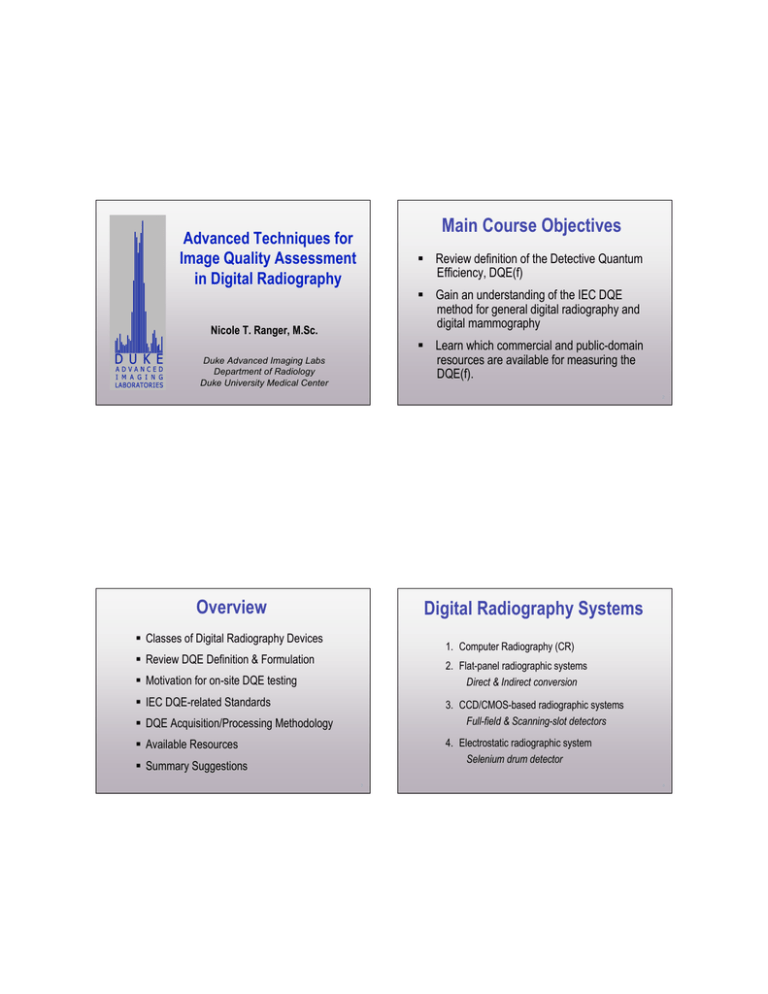
Main Course Objectives Advanced Techniques for Image Quality Assessment in Digital Radiography
advertisement

Main Course Objectives
Advanced Techniques for
Image Quality Assessment
in Digital Radiography
Review definition of the Detective Quantum
Efficiency, DQE(f)
Gain an understanding of the IEC DQE
method for general digital radiography and
digital mammography
Nicole T. Ranger, M.Sc.
Learn which commercial and public-domain
resources are available for measuring the
DQE(f).
Duke Advanced Imaging Labs
Department of Radiology
Duke University Medical Center
2
Overview
Digital Radiography Systems
Classes of Digital Radiography Devices
1. Computer Radiography (CR)
Review DQE Definition & Formulation
2. Flat-panel radiographic systems
Direct & Indirect conversion
Motivation for on-site DQE testing
IEC DQE-related Standards
3. CCD/CMOS-based radiographic systems
Full-field & Scanning-slot detectors
DQE Acquisition/Processing Methodology
4. Electrostatic radiographic system
Selenium drum detector
Available Resources
Summary Suggestions
3
4
MTF and NPS
(conceptually)
Detective Quantum Efficiency
(conceptually)
X-Ray Source
FS
The modulation transfer function (MTF) describes
the frequency response of the imaging system
or how well it preserves signal.
2
SNRout
DQE ( f ) =
SNRin2
The noise power spectrum (NPS) provides the
magnitude and frequency distribution of noise.
Detector
Proc. SPIE: Medical Imaging 2000 – handbook of medical imaging Vol 1.
5
Computation of DQE(ƒ)
DQE( f ) =
=
6
DQE (ƒ) vs “iDQE”
G 2 ! MTF( f ) 2
NPS( f ) ! X ! q
DQE(f) is a rigorous, well-established and relatively
precise metric of DR system performance that must
be performed under highly controlled test conditions
using specialized test tools and software
MTF( f ) 2
NNPS( f ) ! X ! q
iDQE (proposed) is a less precise performance
metric or index of DQE that is measured with a QC
test tool typically supplied by the manufacturer to
track system performance over time
G:
gain factor (digital units per mR)
X:
exposure at detector associated with NPS measurement (mR)
q : ideal SNRin2 (# incident x-ray quanta per unit area per mR)
NNPS: normalized noise power spectrum (NPS/G2 )
7
8
DQE(ƒ) evaluation: DQE
REQUIREMENTS
CLINICAL PHYSICISTS
Good understanding of DQE(f) physics
Specialized (expensive) test equipment and software
Well-trained, “highly motivated” imaging physicist
DQE PHYSICISTS
(aka DQE Gurus)
Measurements should be reproducible with low variability
(IF PERFORMED CORRECTLY)
Infrequently - characterize new devices/technology
9
10
Should clinical physicists be
motivated to learn how to
measure the DQE(f)?
YES
Should DQE(f) evaluations be
performed in the clinical setting?
YES
11
12
Pros
Cons
Continuing medical physicist education
Cost of test equipment
Maintaining a competitive skill-set
Expertise/training requirements
Interest/demand to better understand DQE(f)
High degree of precision required
Increase general body of knowledge
Time-consuming, repetetive measurements & analysis
Correlating DQE(f) & spatial domain FOMs
Frequency domain FOMs less intuitive
Explore relationship between DQE(f) & radiologist
perception/performance
Interpretation is not always easy
Evaluating DQE(f) trends over lifetime of equipment
Potential to undermine confidence in DQE
as a performance metric if done poorly
Verification of manufacturer’s claims
13
Cons
14
IEC DQE Standards
Cost of test equipment
IEC 62220-1:
Expertise/training requirements
General Digital Radiography (pub: 10/2003)
High degree of precision required
IEC 62220-1-2:
Time-consuming, repetetive measurements & analysis
Digital Mammography (pub: 06/2007)
Frequency domain FOMs less intuitive
Interpretation is not always easy
IEC 62220-1-3:
Potential to undermine confidence in DQE
as a performance metric if done poorly
Digital Fluoroscopy (WIP draft)
15
16
Other related IEC Standards
Where to get IEC standards
IEC 61267 Ed. 1:
International Electrotechnical Commission:
Radiation conditions for use in the determination of
characteristics (pub: 09/1994)
http://webstore.iec.ch/webstore
IEC 61267 Ed. 2:
American National Standards Institute:
Radiation conditions for use in the determination of
characteristics (pub: 11/2005)
http://webstore.ansi.org/
17
Digital
Mammography
18
Digital Radiography
19
20
DQE Acquisition Method
DQE Analysis Method
Device Calibration
Compute the Conversion Function
Establish beam quality/technique
Linearize CF, MTF & NPS images
Measure lag time
Compute NPS
Measure the conversion function
Compute MTF
Measure the NPS / Exposure
Rebin data (if necessary)
Measure the MTF
Compute DQE
21
22
Permitted Corrections
for “original data”
Correction for bad detector elements (dels)
Device Calibration
per manufacturer’s
recommendation
Flat-field correction
Correction for radiation field non-uniformity (i.e.Heel Effect)
Gain and offset correction for each detector element
Correction for velocity variation during scan (CR)
Correction for geometric distortion
23
24
IEC Radiation Conditions
General Digital Radiography
X-Ray Source
FS
Establishing Beam Quality
per IEC 61267-1
Added Al Filtration
HVL
Lead Apertures
Radiation
Quality
No.
Approx. Additional
Tube Filtration HVL
Voltage
(mm Al)
(mm Al)
(kV)
RQA3
50
10.0
4.0
RQA5
70
21.0
7.1
RQA7
90
30.0
9.1
RQA9
120
40.0
11.5
≥ 150 cm
12 cm
Detector
≥16 x 16 cm FOV
25
IEC Radiation Conditions
26
Flowchart for IEC 61267 Ed 1 RQA5
Beam Quality
Digital Mammography
X-Ray Source
FS
HVL
Added Filtration
Lead Aperture
60-70 cm
chest
wall
Detector
10 x 10 cm FOV
70 kV tube
voltage
Approx.
Radiation Target
Filter Additional
Tube
HVL
Quality
&
Thickness Filtration
Voltage
(mm Al)
No.
Filter
(mm Al) (mm Al)
(kV)
21 mm Al
Radiation
Quality
No.
Approx. Additional
HVL
Tube Filtration
(mm
Voltage
Al)
(kV) (mm Al)
RQA-M-1 Mo/Mo
25
0.032
2.0
0.56
RQA-M-2 Mo/Mo
28
0.032
2.0
0.60
Using 7.1 mm Al HVL
RQA-M-3 Mo/Mo
30
0.032
2.0
0.62
Measure HVL NB Trans. Fraction
RQA3
50
10.0
RQA-M-4 Mo/Mo
35
0.032
2.0
0.68
70
21.0 7.1
28
0.025
2.0
0.65
TF = 0.5 ± 0.15 ?
RQA5
Mo/Rh
Rh/Rh
28
0.025
2.0
0.74
RQA7
90
30.0
W/Rh
28
0.05
2.0
0.75
W/Al
28
0.50
2.0
0.83
RQA9
120
40.0 11.5
YES
STOP
27
NO
Adjust tube kV
± 1 kV
4.0
9.1
28
Problems with ≥ 99.9% purity Al filtration
IEC Al filtration purity
specification
per 61267 Ed. 1 (and 2)
1. Availability
2. Cost
3. Larger grain size contributes to
radiographic non-uniformities
≥ 99.9% purity Al
29
30
Problems with ≥ 99.9% purity Al filtration
Lower purity
Al alloy
“gold standard”
A & D: Alfa Aesar
B & C: Goodfellow Corp
Med Phys 32: 2305-2311 (2005)
LP Al
UHP Al
1 mm
A
B
1 mm
UHP Al
Annealed
D
C
UHP Al
2 mm
640 x 640 pixels
Lag Time
10.5 mm
LP: 99.0% purity
UHP: ≥ 99.99% purity
31
32
Practical Advice
Follow the manufacturer’s recommendations
Wait the minimum specified interval of time between
image acquisitions – longer when imaging high contrast
objects. (Better to be conservative than sorry.)
Determining the conversion
function
Acquire images in a progression from:
1.
2.
low to high exposures
low to high contrast
Protect the detector when taking high exposure
measurements by draping it with Pb apron(s)
33
34
Conversion Function
Exp. Range: 0 - 4Enl
IEC Standard
beam geometry/quality
RQA/RQM
LINEAR systems
Use 5 mAs stops
spanning full range
35
100 x100
ROI
All other systems
Use “N” mAs stops
such that logEi-logEi+1 ≤ 0.1
for i = 1, N-1
36
Determining the inverse CF:
E=e
PVlin = F -1 (PVorig )
(PVorig !2710.3)
367.55
( PVorig )
= k ! e 367.49
where
PVorig=367.55Ln(E)+2710.3
R2=1
PVlin = C ! E
PVlin = C ! E
( PVorig )
PVlin = C " ! e 367.49
37
38
for i =1:30;
info=dicominfo(['im',num2str(i),'_NNPS.dcm']);
% read DICOM Meta Data
filename=info.Filename
xdim=info.Columns
ydim=info.Rows
DIM=dicomread(['im',num2str(i),'_NNPS.dcm']);
% Read DICOM Image
% dicomread('filename.dcm')
Mean Pixel Counts
Linearize
images
fmaxval_1=max(max(DIM))
slope=367.55;
% slope of PV vs lnE
alpha=double(1.0/slope);
sf=2.521273243
% sf which yields final slope of 4000;
% so that PVlin=4000E
LPV=exp(alpha*double(DIM));
sDIM=(sf * LPV);
After linearization
Before linearization
fmaxval_2=max(max(sDIM))
Example using
Matlab v7.4
for Mac OS X 10
% write linearized raw file
rDIM=rot90(sDIM);
fDIM=flipdim(rDIM,1);
fid=fopen(['im',num2str(i),'_NNPS_linearized.raw'],'w');
fwrite(fid,fDIM,'uint16','ieee-be');
fclose(fid);
end
39
Exposure at detector (mR)
40
NPS Irradiated/Analysis
Irradiated Analysis Area:
≥ 16 x 16 cm
chest
wall
Measuring the NPS
12.5 x 12.5 cm
41
For each of N images, the NPS analysis area is
divided into 256 pixels x 256 pixels ROIs
1:
2:
3:
4:
3
Digital Mammography
E nl
, E nl , 3.2E nl
3.2
E nl
, E nl , 2E nl
2
Where Enl is normal exposure level specified by the manufacturer
subtract
2D 2nd order polynomial
background fit
(detrending correction)
42
Frequency Domain
ROI
detrended
original
ROI “ensembles” are replicated and overlapped by
shifting their reference coordinates by 128 pixels
2
Digital Radiography
ROI
N = # of images to achieve
“4 million independent pixels”
ROI ensemble
reference point
( ) for each pass
5 x 5 cm
Spatial Domain
256
1
10 x 10 cm
2D FFT
of each ROI
4
(x,y)
(x+128, y)
(x, y+128)
(x+128, y+128)
average all 2D NPS
images for the ROI
ensemble/group
43
2D NPS image
44
The x- and y- NPS results are obtained by
band-averaging each freq. bin ± 7 pixels
on either side of the x- and y-axes (axes excluded)
2-D NPS
1-D NPS Plot
ƒy
NPS Directional Dependence
Measuring the MTF
1.0E-04
Horizontal
Intensity
∝ noise amplitude
Vertical
ƒx
Zeroeth spatial
freq @ origin
1.0E-05
ƒx
i
1.0E-06
0.0
0.5
1.0
1.5
2.0
2.5
Spatial Frequency (cycles/mm)
45
MTF Test Device: IEC 62220-1 (General)
46
MTF On-Axis Alignment Dependence
• 90% Tungsten, 1.0 mm thick,
1.0
100 x 75 (min) mm area
50 mm x 100 mm
0.9
• highly polished 90˚edge
• 3 mm thick Pb plate surround
• Angular offset 1-3˚ from axis.
• Measure at detector surface
in X(A) and Y(B) directions
using FS < 1.0 mm
A
OE@0cm
OE@1cm
OE@2cm
OE@3cm
OE@4cm
OE@6cm
OE@8cm
OE@10cm
0.8
B
0.6
MTF
IEC 62220-1
Compliant
radio-opaque
edge device
0.7
0.5
0.4
0.3
0.2
Co-ordinate
system
@ beam/det. center
0.1
0.0
0.0
1.0
2.0
3.0
4.0
5.0
6.0
Spatial Frequency (cycles/mm)
47
Med Phys 33: 1454-1465 (2006)
48
MTF Analysis
MTF Test Device: IEC 62220-1-2 (Mammo)
• Type 304 stainless steel
• 0.8 mm thick, 120 mm x 60 mm
• highly polished 90˚edge
• Angular offset 1-3˚ wrt axis.
• Measure at detector surface:
A,B for DR
A,B,C,D for CR
A
DETECTOR
Extracted Edge
Segment
OR
ESF
LSF
edge
projection
B
C
differentiation
(from linearized image
of MTF device)
D
Chest
wall
6 cm
TOP VIEW
49
Example shows 100 mm x 50 mm edge image per IEC 62220-1 (General DR)
50
Spatial Frequency Sampling
for DQE Computation
MTF Analysis
IEC REQUIREMENT
LSF
MTF
Fourier
Transform
Spatial Frequency Interval, ƒint
Self-Normalization
at f=0
where ƒint
Average data
in freq. interval:
51
=
0.01
pixel pitch (mm)
ƒ -ƒint
ƒ +ƒint
52
Spatial Frequency Rebinning
WHY ?
Computing DQE(ƒ)
To comply with standard requirements
To match frequency sampling of NPS &
MTF for computation of the DQE
Reduces variance per frequency bin
53
Computation of DQE(ƒ)
q-values per IEC 62220-1
G 2 ! MTF( f ) 2
DQE( f ) =
NPS( f ) ! X ! q
RQA3
RQA5
RQA7
RQA9
2
=
54
MTF( f )
NNPS( f ) ! X ! q
G:
gain factor (digital units per mR)
X:
exposure at detector associated with NPS measurement (mR)
q : ideal SNRin2 (# incident x-ray quanta per unit area per mR)
NNPS: normalized noise power spectrum (NPS/G2 )
21759 1/(mm2-µGy) or
30174
32362
31077
190,826 1/(mm2-mR)
264,626
“
283,815
“
272,545 “
µGy: micro-Gray (SI unit)
mR: milli-Roentgens
55
56
DQE of a Range of DR Systems
Reporting DQE
IEC REQUIREMENT
DQE is reported at spatial frequencies intervals
of 0.5, 1.0, 1.5 mm-1 …. from 0.5 mm -1
up to the Nyquist Frequency.
Nyquist Frequency (mm -1) =
Data provided compliments of Alistair MacKenzie of K-CARE (UK)
1
2 · pixel pitch (mm)
57
58
EQUIPMENT
Well-calibrated ionization chamber
with an uncertainty of ≤ 5.0 %
RESOURCES
Precision-machined MTF edge device
Lead apertures (optional)
Radiographic quality Al filtration
59
60
Contributors:
• Ehsan Samei
DQE EVALUATION
SOFTWARE
• Robert Saunders
• Andrew Maidment
• Jeff Siewerdsen
61
62
Recommendations
Take advantage of the free resources available
Invest in a high quality edge device
Use lower purity (99.0%) Al, i.e. Type 1100 not
the ≥ 99.9% purity Al specified by the standard
Test Al before use!
63
64
Thank you for your attention.
Recommendations
Review the fundamentals of DQE physics
Study the literature on DQE testing
Obtain the IEC standards for reference
Recruit a “DQE Mentor”
Email: nicole.ranger@duke.edu
65
Thank You
for
Your Attention
67


