Geometrical Optics
advertisement

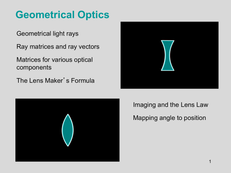
Geometrical Optics Geometrical light rays Ray matrices and ray vectors Matrices for various optical components The Lens Maker’s Formula Imaging and the Lens Law Mapping angle to position 1 Leerdoelen In dit college leer je: • Wat de benaderingen zijn van geometrische optica • Wat de belangrijkste karakteristieken van lenzen zijn • Hoe je de stralengang door optische systemen met o.a. lenzen kunt analyseren • Een matrix-methode voor geometrische optica • Toepassing: microscopie, fotografie en bijbehorende eigenschappen • Hecht: 5.1 t/m 5.4; 5.7; 6.1 en 6.2 2 Is geometrical optics the whole story? No. We neglect the wave nature of light. ~0 Also, our ray pictures seem to imply that, if we could just remove all aberrations, we could focus a beam to a point and obtain infinitely good spatial resolution. Not true. The smallest possible focal spot is the on the order of the wavelength l. Same for the best spatial resolution of an image. This is due to diffraction, which is not included in geometrical optics. ≈l 3 Arguments in favor of geometrical optics Remember week 1 in which we discussed three reasons to believe that the ray picture of light is useful: 1. The straight propagation of light that we see entering through a window. 2. The camera obscura in which a small aperture produces an image that is upside down. 3. The very narrow beams that are produced by a laser. 4 Relation between object, image and focus 1 1 1 f s 0 si yo yi f f s1 s0 Magnification: yi si MT yo so 5 Lensmaker’s formula 1 1 1 1 nl 1 so1 si 2 R1 R2 1 1 1 nl 1 f R1 R2 1 1 1 f s 0 si 8 Types of lenses Lens nomenclature: Which type of lens to use (and how to orient it) depends on the aberrations (next lecture) and application. 9 Sign convention for R 10 Tracing a few rays (Fig 5.20 Hecht) • Rays through the center of the lens go straight • Parallel rays from the object pass through Fi • Rays through Fo propagate parallel to the axis behind the lens 11 Image formation by a thin lens 1 1 1 f s 0 si yi si MT yo so • • • • The image is formed at the point where these rays cross A real image is formed if s0 > f The magnification of the image is given by Mt For a single positive lens, the magnification will be negative 12 Virtual Images A virtual image occurs when the outgoing rays from a point on the object never actually intersect at a point but can be traced backwards to one. Negative-f lenses have virtual images, and positive-f lenses do also if the object is less than one focal length away. Virtual image Virtual image Object infinitely far away Object f<0 Simply looking at a flat mirror yields a virtual image. f>0 13 Combination of 2 lenses spaced < F1, F2 14 Ray Optics axis We'll define light rays as directions in space, corresponding, roughly, to k-vectors of light waves. We won’t worry about the phase. We also ignore reflections. Each optical system will have an axis, and all light rays will be assumed to propagate at small angles to it. This is called the Paraxial Approximation: sin q tan q q 15 The Ray Vector xin , qin xout, qout A light ray can be defined by two coordinates: its position, x q its slope, q x Optical axis These parameters define a ray vector, which will change with distance and as the ray propagates through optics. x q 16 Ray Matrices For many optical components, we can define 2 x 2 ray matrices. An element’s effect on a ray is found by multiplying this matrix with the ray vector. Ray matrices can describe simple and complex systems. Optical system ↔ 2 x 2 Ray matrix xin q in A C B D xout q out These matrices are often (uncreatively) called ABCD Matrices. 17 Physical meaning of two of the matrix elements 𝐴= 𝑥𝑜𝑢𝑡 𝑥𝑖𝑛 𝑖𝑓 𝜃𝑖𝑛 = 0 𝐷= 𝜃𝑜𝑢𝑡 𝜃𝑖𝑛 𝑖𝑓 𝑥𝑖𝑛 = 0 spatial magnification xout A B xin q C D q in out angular magnification 18 For cascaded elements, we simply multiply ray matrices. xin q in O2 O1 xout q O3 O2 out O1 O3 xout q out xin xin q O3 O2 O1 q in in Notice that the order looks opposite to what it should be, but it makes sense when you think about it. 19 Ray matrix for free space or a medium If xin and qin are the position and slope upon entering, let xout and qout be the position and slope after propagating from z = 0 to z. xout qout Xin, qin xout = xin + z qin q out = qin Rewriting these expressions in matrix notation: z z=0 Ospace 1 z = 0 1 é x ê out êq ë out ù é 1 z ùé xin ù ú = ê ú úê ú êq ú 0 1 ë û û ë in û 20 Ray Matrix for an Interface qout At the interface, clearly: qin xout = xin. n1 Now calculate qout. Snell's Law says: xin xout n2 n1 sin(qin) = n2 sin(qout) which becomes for small angles: n1 qin = n2 qout qout = [n1 / n2] qin é 1 0 Ointerface = ê êë 0 n1 / n2 ù ú úû 21 Ray matrix for a curved interface [radius R ] At the interface, again: xout = xin. To calculate qout, we must calculate q1 and q2. If qs is the surface slope at the height xin, then R qs q2 q1 qin xin n1 z=0 qout qs z qs = xin /R n2 z q1 = qin+ qs and q2 = qout+ qs q1 = qin+ xin / R and q2 = qout+ xin / R Snell's Law: n1 q1 = n2 q2 n1 (qin xin / R) n2 (qout xin / R) qout (n1 / n2 )(qin xin / R) xin / R é 1 0 qout (n1 / n2 )qin (n1 / n2 1) xin / R Ocurved = ê (n / n -1) / R n / n interface ê 1 2 ë 1 2 22 ù ú úû A thin lens is just two curved interfaces. We’ll neglect the glass in between (it’s a really thin lens!), and we’ll take n1 = 1. Ocurved interface 1 0 ( n / n 1) / R n / n 1 2 1 2 R1 n1=1 R2 n2≠1 n1=1 1 0 1 0 Othin lens Ocurved Ocurved (1/ n 1) / R 1/ n ( n 1) / R n interface 2 interface 1 2 1 1 0 1 0 ( n 1) / R n (1/ n 1) / R n (1/ n ) ( n 1) / R (1 n ) / R 1 2 1 2 1 1 0 ( n 1)(1/ R 1/ R ) 1 2 1 This can be written: where: 1/ f (n 1)(1/ R1 1/ R2 ) 1 1/ f 0 1 The Lens-Maker’s Formula 23 Next: justify that f = focal length Ray matrix for a lens 1/ f (n 1)(1/ R1 1/ R2 ) Olens é 1 = ê êë -1/f 0 1 ù ú úû The quantity, f, is the focal length of the lens. It’s the single most important parameter of a lens. It can be positive or negative. R1 > 0 R2 < 0 f>0 If f > 0, the lens deflects rays toward the axis. R1 < 0 R2 > 0 f<0 If f < 0, the lens deflects rays away from the axis. 24 A lens focuses parallel rays to a point one focal length away. A lens followed by propagation by one focal length: é x ê out êq ë out ù ú= ú û é 0 é x ù ù 0 ê in ú ú = ê 1 úûêë 0 úû êë -1/f é 1 f ùé 1 ê úê êë 0 1 úûêë -1/f f f f ùé xin úê 1 úûêë 0 For all rays xout = 0! ù é ù 0 ú=ê ú úû êë -xin / f úû Assume all input rays have qin = 0 At the focal plane, all rays converge to the z axis (xout = 0) independent of input position. [Parallel rays at a different angle focus at a different xout.] Notice we have now proven the Lensmakers’ Law. 25 Concave Spherical Mirror A concave mirror A radio telescope Like a lens, a curved mirror will focus a beam. Its focal length is R/2, with R the radius of curvature. 26 Ray Matrix for a Curved Mirror Consider a mirror with radius of curvature, R, with its optic axis perpendicular to the mirror: q1 qin q s q s xin / R R qout qs qin qout q1 q s (qin q s ) q s qin 2 xin / R q1 q1 xin = xout z 0 1 Omirror = 2 / R 1 Like a lens, a curved mirror will focus a beam. Its focal length is R/2. Note that a flat mirror has R = ∞ and hence an identity ray matrix. 27 Consecutive lenses Suppose we have two lenses right next to each other (with no space in between). 1 Otot = -1/f 2 f1 0 1 0 1 = 1 -1/f1 1 -1/f1 1/ f 2 f2 0 1 1/f tot = 1/f1 + 1/f 2 So two consecutive lenses act as a single lens whose focal length is computed by the inverse sum. As a result, we define a measure of inverse lens focal length, the diopter. 1 diopter = 1 m-1 28 A system images an object when B = 0. When B = 0, all rays from a point xin arrive at a point xout, independent of their angle. xout = A xin é x ê out êq ë out ù é é x ù é ù Axin ú = ê A 0 úê in ú = ê ú ë C D ûê q ú ê C x + D q in û ë in û ë in When B = 0, A is the magnification. 29 ù ú ú û The Lens Law From the object to the image, we have: 1) A distance do 2) A lens of focal length f 3) A distance di 0 1 d o 1 d i 1 O 1/ f 1 0 1 0 1 do 1 di 1 1/ f 1 d / f 0 1 o 1 di / f d o di d o di / f 1/ f 1 d / f o B d o di d o di / f do di 1/ d o 1/ di 1/ f 0 if 1 1 1 d o di f This is the Lens Law. 30 Imaging Magnification If the imaging condition, 1 1 1 d o di f is satisfied, then: 1 di / f O 1/ f 1 do / f 1 1 A 1 di / f 1 di d o di di M do 0 1/ M 1 1 D 1 do / f 1 do d o di do 1/ M 31 di 0 So: M O 1/ f Microscopes Image plane #1 Objective M1 Eyepiece Image plane #2 M2 Microscopes basically consist of a set of lenses, and is used to: 1. In a microscope, the object is really close and we wish to magnify it. 2. Lens aberrations should be minimized (next lecture). A microscope is effectively a telescope in reverse. The goal is to magnify the object, not its angular diameter. Eyepiece The microscope objective yields a magnification of from 5 to 100, corresponding to focal lengths of 40 mm to 2 mm. The eyepiece yields a magnification of 2 to 10, corresponding to various focal lengths and distances. Objective 32 Microscope Terminology 33 F-number The F-number, “f / #”, of a lens is the ratio of its focal length and its diameter. f/# = f/d Confusing!! For example, a lens with a 25 mm aperture and a 50 mm focal length has an f-number of 2, which is usually designated as f/2 f d1 f f d2 f/# =1 f f/# =2 Small f-number lenses collect more light but are harder to engineer. 34 Depth of Field Only one plane is imaged (i.e., is in focus) at a time. But we’d like objects near this plane to at least be almost in focus. The range of distances in acceptable focus is called the depth of field. It depends on how much of the lens is used, that is, the aperture. Out-of-focus plane Image Object f Aperture Size of blur in out-of-focus plane Focal plane The smaller the aperture, the greater the depth of field. 35 Depth of field example A large depth of field isn’t always desirable. f/32 (very small aperture; large depth of field) f/32 means f/D = 32, the focal length of the lens is 32 times larger than the aperture diameter f/5 (relatively large aperture; small depth of field) A small depth of field is also desirable for portraits. 36 Tot slot Wat hebben we gezien: • Geometrische optica • Berekeningen met lenzen • ABCD-matrix voor optische systemen • Matrix-berekeningen in geometrische optica • Inleiding in microscopie 37


