Clinical Implementation of Non-Physical Wedges
advertisement
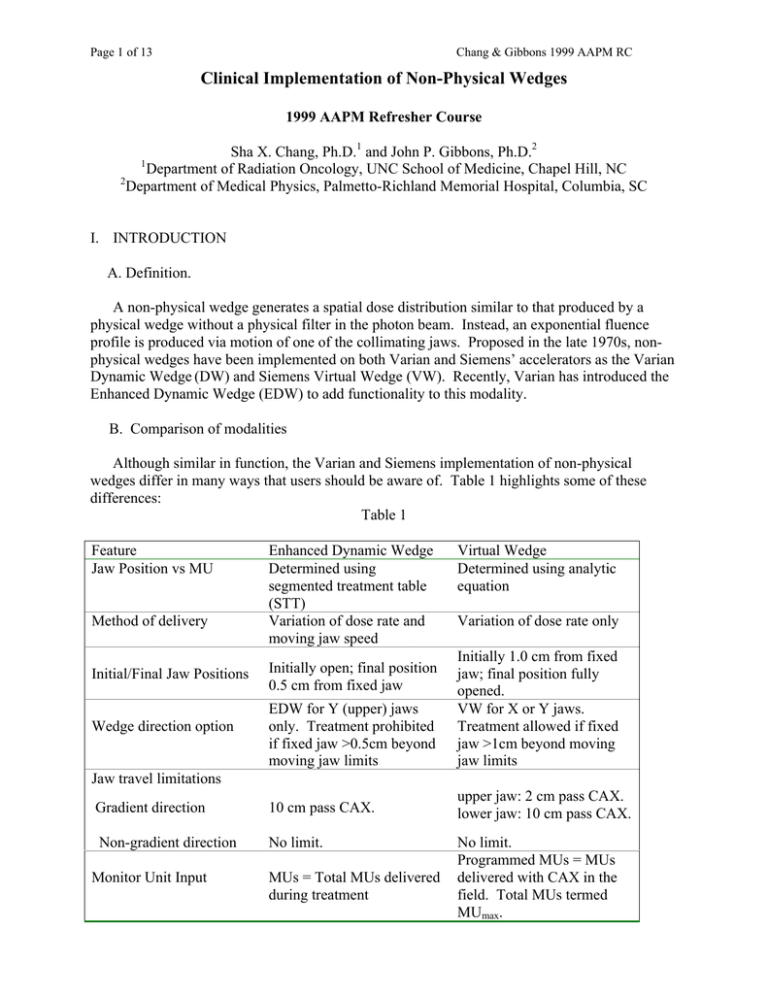
Page 1 of 13 Chang & Gibbons 1999 AAPM RC Clinical Implementation of Non-Physical Wedges 1999 AAPM Refresher Course Sha X. Chang, Ph.D.1 and John P. Gibbons, Ph.D.2 1 Department of Radiation Oncology, UNC School of Medicine, Chapel Hill, NC 2 Department of Medical Physics, Palmetto-Richland Memorial Hospital, Columbia, SC I. INTRODUCTION A. Definition. A non-physical wedge generates a spatial dose distribution similar to that produced by a physical wedge without a physical filter in the photon beam. Instead, an exponential fluence profile is produced via motion of one of the collimating jaws. Proposed in the late 1970s, nonphysical wedges have been implemented on both Varian and Siemens’ accelerators as the Varian Dynamic Wedge (DW) and Siemens Virtual Wedge (VW). Recently, Varian has introduced the Enhanced Dynamic Wedge (EDW) to add functionality to this modality. B. Comparison of modalities Although similar in function, the Varian and Siemens implementation of non-physical wedges differ in many ways that users should be aware of. Table 1 highlights some of these differences: Table 1 Feature Jaw Position vs MU Method of delivery Enhanced Dynamic Wedge Determined using segmented treatment table (STT) Variation of dose rate and moving jaw speed Virtual Wedge Determined using analytic equation Variation of dose rate only EDW for Y (upper) jaws only. Treatment prohibited if fixed jaw >0.5cm beyond moving jaw limits Initially 1.0 cm from fixed jaw; final position fully opened. VW for X or Y jaws. Treatment allowed if fixed jaw >1cm beyond moving jaw limits Gradient direction 10 cm pass CAX. upper jaw: 2 cm pass CAX. lower jaw: 10 cm pass CAX. Non-gradient direction No limit. Initial/Final Jaw Positions Wedge direction option Initially open; final position 0.5 cm from fixed jaw Jaw travel limitations Monitor Unit Input MUs = Total MUs delivered during treatment No limit. Programmed MUs = MUs delivered with CAX in the field. Total MUs termed MUmax. Page 2 of 13 Chang & Gibbons 1999 AAPM RC Feature Wedge Angle Selection Enhanced Dynamic Wedge 7 wedge angles (10o, 15o, 20o, 25o, 30o, 45o, 60o) Wedge Factors Strong function of both wedge angle and field size; Weak function of off-axis distance. STTs same for all Varian machines Machine-independence II. Virtual Wedge Continuous to 60o; Larger angles available with reduced field sizes. Approximately unity (!5%) for symmetric fields; Strong function of off-axis distance. VW equation may vary with user-adjustable calibration factor c. MONITOR UNIT CALCULATIONS: NON-PHYSICAL WEDGE FACTORS A. Field Size Dependence Both DW and EDW show strong field size dependence. Measured DW factors (Fig. 1) exhibit a discontinuity between 9.5 and 10 cm width due to change in STT step size. Measured EDW factors (Fig. 2) are derived from a single table and have a smooth field size dependence. In both cases, the wedge factors have been shown to be closely approximated by the fraction of monitor units delivered with the central axis in the field (“MU fraction” model). Additionally, EDW factors appear to be machine-independent to within 1%. Figure 1 Figure 2 EDW factors can be determined in several ways. In addition to direct measurement, inspection of the STT prior to treatment to determine the MU fraction will provide adequate Page 3 of 13 Chang & Gibbons 1999 AAPM RC prediction of the EDW factor in most cases. Since the EDW treatment STT is smooth, an analytic function6 may also be used to describe this quantity. Virtual wedge factors are close to unity for all symmetric fields of different wedge angles. The wedge factor will deviate from unity for asymmetric fields when the wedge factor is calculated on the center of the asymmetric fields. Measured virtual wedge factors (Fig. 3) show variation less than !5% for range of field sizes and wedge angles. The systematic deviation of VWF at large wedge angles and field sizes can be corrected using a wedge factor file/table for the VWF calculation. Figure 3. Virtual wedge factor vs. wedge angle 1.04 6X, obs 18X, obs 6X,10x10 18X, 10x10 VWF 1.03 1.02 1.01 1 0.99 0 20 40 60 80 ANGLE (DEG) Variation from the “MU fraction” model may exceed clinical tolerance for MU calculations for large field size, wedge angle combinations. Measured values for these cases can be input into clinical tables. An extension to the “MU fraction” model can be used to determine both EDW and VW factors to within 2%. Resulting EDW factors using this approach for 6X and 18X EDW factors are displayed in Tables 2 (left) and 3 (right), respectively. Page 4 of 13 Chang & Gibbons 1999 AAPM RC B. Depth Dependence Unlike physical wedges, the dosimetry of non-physical wedges shows far less variation with depth in the absence of the beam hardening effect. A slight increase in measured PDD has been demonstrated with both Dynamic and Virtual wedges and this has been attributed to a secondary effect of the exponential fluence distribution. In most cases, the dosimetric variations are less than 2%. C. Off-Axis Dependence Both EDW and VW allow asymmetric fields in either the non-gradient and/or gradient directions. In the non-gradient direction, no deviation from open field values has been reported. In the gradient direction, EDW factors can vary by up to 15%, while VW factors may vary by more than 100%. For wedge factors defined at the geometric center of the field, analytic models have shown agreement within 2%. Figure 4 and 5 displays off-axis EDW and VW factors for 30o non-physical wedges for 6MV and 18MV photons, respectively. Figure 4. EDW factor of 30degree wedge and 6MV. Three sets of data are for field size 5x5 (circles), 10x10 (squares), and 20x20 (triangles). Field Center (off-axis) 1.4 Figure 5. VW factor for 6MV (squares) and 18 MV (circles) at field size of 5x5 at different field center position. 1.2 1 0.8 0.6 0.4 0.2 0 -20 -15 -10 -5 0 OFF AXIS DISTANCE 5 10 Page 5 of 13 III. Chang & Gibbons 1999 AAPM RC Implementation of non-physical wedges into a Treatment Planning System (TPS) The dynamic nature of the non-physical wedge functions offers great ease for photon beam treatment delivery. However, it poses a considerable challenge to most of the available TPS', whose data structures inherently assume that the radiation beams are static. There are three types of implementation methods for incorporating a non-physical wedge of choice into a TPS: 1) photon fluence modeling 2) physical wedge emulation 3) synthesis of two or more wedge fields Depending on the flexibility of the TPS on hand one can use at least one of the three types of the methods to incorporate the non-physical wedge function. 1. Photon fluence modeling Photon fluence modeling is the ideal choice of all TPS implementation methods. It requires a sophisticated TPS that is able to model the photon fluence actually generated by the non-physical wedge delivery process. As a result, all aspects of treatment planning can be accurately performed with the consideration of all specific limitations of the non-physical wedge of the concern. Unfortunately, only a few TPS are truly equipped with such flexibility. This type of TPS includes the Univ. of North Carolina in-house TPS PLUNC [Chang et al 1999] and ADAC's Pinnacle3 [Bayouth & Steinberg] for VW. For EDW such TPS' are CadPlan of Varian-Dosetek [Salk et al, Samuelsson et al 1997], IsiS3D of Technologie of Diffusion [Papathoedorou et al 1999], and Multidata DSS v2.35 [Beavis et al 1996]. Helax TMS TPS is also reported to have such a function [Karlsson 1997]. PLUNC computes the doses based on the photon fluence generated by the virtual wedge with the consideration of head scatter variation during the dynamic treatment delivery. Others TPS' model the photon fluence by superpositioning many segment treatment fields based on the STT table for EDW and the output rate analytical equation for VW. These methods realistically simulate the actual wedge treatment delivery and therefore produce reliable results in terms of both the relative dose distribution and the absolute MU calculation. The figure below by Bayouth & Steinberg shows there is a very good agreement between calculated and measured beam profiles of different wedge angles (Figure 6) of VW. Table 4 displays the excellent agreement between measured wedge factors and the calculation by PLUNC for 6MV photon for both symmetric and asymmetric fields and at different depth. Figure 6. Beam profile data from Bayouth & Steinberg (unpublished). VW angles measured ranging from 10 to 70 degrees. Excellent agreement between the measured data (solid lines) using linear array detectors and the corresponding calculation (symbols) using Pinnacle3 TPS from ADAC. Page 6 of 13 Chang & Gibbons 1999 AAPM RC Table 4. 6 MV VW factor comparison (Univ. of North Carolina) Field size (x1,x2,y1,y2) 5,5,5,5 Depth (cm) 1.5 Wedge dir. 15W 30W 45W 60W 1(calc.) 1(meas.) 0.998 1.004 0.6 0.997 1.004 0.7 1.003 1.008 0.5 1.003 1.011 0.8 0.851 0.857 0.7 0.860 0.866 0.7 1.169 1.177 0.7 1.158 1.161 0.3 1.001 1.012 1.1 1.001 1.013 1.2 1.011 1.019 0.8 1.012 1.025 1.3 0.759 0.754 0.6 0.775 0.783 1.0 1.316 1.324 0.6 1.294 1.295 0.1 1.007 1.024 1.7 1.008 1.032 2.3 1.029 1.041 1.1 1.035 1.055 1.9 0.625 0.632 1.1 0.648 0.656 1.2 1.618 1.624 0.4 1.571 1.568 0.2 % difference % difference 10,10,10,10 10.0 1 (calc.) 1 (meas.) 1.5 1 (calc.) 1 (meas.) 10 1 (calc.) 1 (meas.) 1.5 1 (calc.) 1 (meas.) 10.0 1 (calc.) 1.5 2 (calc.) 2(meas.) 10 2 (calc.) 2 (meas.) % difference % difference 5,5,0,10 % difference % difference 5,5,0,10 % difference % difference 0.997 0.997 0.0 0.997 0.997 0.0 1.0 0.998 0.2 1.0 0.999 0.1 0.926 0.930 0.4 0.930 0.933 0.3 1.072 1.076 0.4 1.068 1.069 0.1 2. Physical Wedge Emulation Physical wedge emulation is the most common method used in non-physical wedge TPS implementation. The non-physical wedges are made to emulate the corresponding physical wedges in the TPS. Because of some intrinsic differences between the physical and non-physical wedges the latter cannot emulate the former in all aspects. Users must take extreme precautions in this emulation approach to ensure the safe and accurate clinical application. The differences between physical and non-physical wedges include the unique wedge factor variation with field size and wedge angle, and the lack of depth dependence of wedge factor due to the absence of beam hardening effect in non-physical wedged beams. A number of commercial TPS have incorporated EDW using this emulation method: they include, CMS, ROCS, Pinnacle, and TheraPlan. Depending on the specific requirements of each TPS, the beam data required for nonphysical wedge TPS implementation could be different. They include a) non-physical wedge beam profiles of different wedge angles, field sizes, and depths; b) wedge factor of different wedge angles, field sizes, and off-axis distance, or c) wedge filter files which specify the physical description of the wedge filters. The wedge filter files can be generated with the following method based on measured non-physical wedge data. Measure beam profiles W (x, y) along wedge direction x at a fixed depth and SSD and at different off-axis distance y (the central axis is at x = y = 0). Only one direction of off-axis is needed because of the wedge symmetry. Measure the corresponding open field profiles O(x,y) and calculate the ratio of the wedged and open profiles, Page 7 of 13 Chang & Gibbons 1999 AAPM RC R(x,y)|SAD,d = W(x,y)|SAD|/ O(x,y)|SAD,d where SAD = SSD +d If the filter to source distance on the accelerator is FSD, the virtual wedge filter file f (x', y', d')|SFD can be calculated based on the measured data above and a given linear attenuation coefficient µ value. x' = (SFD/SAD) x; y' = (SFD/SAD) y; The thickness of the filter at location (x', y'), d', can be calculated using a simple exponential function: R(x,y) = e - µ d'/cos θ 2 2 1/2 where tan θ = [x' + y' ] / SFD The cosine term basically solves the beam divergence issue in the filter file calculation. In contrast to the physical wedges, both the VW and the EDW have different asymmetric field size limitations for different wedge directions due to the constraints of the jaw travel range as described previously (Table 1). For example, for an asymmetric 20x30 (30 = 10, 20) field only one wedge direction is possible in the long dimension of the field. The opposite wedge direction is not possible because the moving jaw can only travel across the central ray 10cm. It is very desirable to install this field size limitation into each wedge filter file if possible. The wedge filter files can also be created from the STT table with good results [Klein 1997]. Although physical wedge emulation methods enable almost any "closed" commercial TPS to adopt non-physical wedges, the challenge lies in the wedge factor computation, which is quite different than that of the physical wedges. In addition, one needs to fully understand those aspects of the non-physical wedge that cannot be emulated in the TPS. For example, nonphysical wedges do not have the beam hardening effect physical wedges often possess therefore no such correction is needed. 3. Synthesis of two or more wedge fields This type of non-physical wedge implementation is not very different from the physical wedge emulation methods. It uses beam data from an open field and one or more wedged fields to synthesize a non-physical wedge of any angle up to the largest wedge angle which beam data is used for the synthesis. Compare to the method of physical wedge emulation this method requires fewer beam profile measurements for TPS commissioning. EDW is ideal for such an implementation method considering it is intrinsically composed of an open field and a 60-degree wedged field with appropriate weighting. Several wedge angles are reportedly used to synthesize VW beam profiles. The concern with this multiple wedged beams method is that it may introduce complexity in wedge factor calculation since wedge factor calculation must be synthesized as well. In fact, it may not be a far reaching idea to bypass the complications encountered in the simulation of the non-physical wedges in the TPS altogether by using a combination of open and a 60-degree wedged fields of appropriate beam weighting. In this manner, the advantage of the treatment automation is preserved as well as the simplicity and accuracy of the conventional treatment planning technique. Page 8 of 13 IV. Chang & Gibbons 1999 AAPM RC Non-physical wedge TPS commissioning and measurement tools The method of the TPS commissioning depends on the way the non-physical wedge is implemented into the TPS. Once the implementation method is chosen the commissioning should provide all necessary beam data and the verification of the TPS output accuracy in terms of all clinically relevant parameters. A variety of different treatment situations should be evaluated during the commissioning to verify the accuracy of the TPS, and to identify the circumstances when the implementation method fails to give correct answers. Such verification is especially crucial for the physical wedge emulation and synthesis implementation methods, which cannot correctly simulate the non-physical wedge functions in all aspects. Prior to the TPS commissioning the non-physical wedge function itself must be commissioned first. This commissioning includes the verification of the accelerator output rate variation as a function of jaw motion, wedge angle, field size, and other relevant parameters, regardless of if the function is governed by an analytical equation (VW) or a STT (EDW). The photon fluence modeling type of implementation method requires the least amount of data collection for both the VW and EDW. Standard beam data collection, which is normally used for static open field treatments, are used for the photon fluence modeling type of TPS implementation. Almost no special beam data (non-physical wedge beam) collection is needed for data input to the TPS. However, non-physical wedge data collection is still indispensable for TPS implementation verification. Non-physical wedge beam profile and wedge factor measurements are often required by the physical wedge emulation and synthesis methods. Beam profile measurements of a dynamic treatment can be done rather conveniently using commercially available multi-detectors array systems but it is also doable using standard dosimetry equipment. The Profiler™ diode-array measurement system is an ideal tool for dynamic treatment measurements in commissioning and routine QA. Besides collecting the conventional cumulative dose information the Profiler system is also capable of collecting time-dependent information, which can be used to measure both the collimator jaw speed (figure 8) and the output rate variation during VW irradiation. An ion chamber array detector system by Wellhöfer is also commonly used for the commissioning measurement. A simple technique of using a single ion chamber [Bayouth & Steinberg] can produce the above results with good accuracy. Figure 8. Virtual wedge jaw speed measured by Profiler™ detector array using a special time-dependent measurement mode. Beam profile was collected every second during VW irradiation. The moving field edge, represented by the point on the beam penumbra where the slope is the largest, was analyzed as a function of time. The measured jaw speed was within 1% of the expected value of 4.0 mm/sec in this case. Page 9 of 13 V. Chang & Gibbons 1999 AAPM RC Small field size and photon source model effects Non-physical wedge treatments involve irradiation through very small and often off-axis openings that are not frequently encountered and therefore may not be well-evaluated in conventional static treatments. Dynamic wedge treatment uses field widths as small as 5 mm and 10 mm for virtual wedge treatment. The accuracy of the dose and MU calculation for these small field width situations is highly dependent on the accuracy of head scatter data in this region and on the photon source model used in the TPS. Head scatter data must be directly measured in the small field region instead of extrapolating data of larger field sizes (even 4cmx4cm). Significant error can occur in MU calculation of the small segment fields if one extrapolates head scatter data from fields where lateral electronic equilibrium condition is satisfied to small fields where the condition does not exist. Figure 9 shows the dose decrease with reduced field width due to both the lack of lateral electronic equilibrium in the measurement media and the reduced photon fluence from the source. Figure 9 clearly shows that a simple linear extrapolation from data of field size above 4x4 can severely over-estimate the dose, or under-estimate the MU required to deliver a given dose in the narrow field situations. The reduction of photon fluence in narrow and off-axis field situations is illustrated by Figure 10. Only a portion (shaded area) of the photon source volume (indicated by a sphere) is "seen" from the measurement location under the narrow and off-axis field. The amount of the source "seen" or the amount of photon fluence at the measurement location depends on the jaw settings and the measurement location itself. Obviously the reduction of the photon fluence in Figure 10 is highly source model dependent. The TPS photon source model which describes the intensity distribution of the photon source in the accelerator head should be modified and verified so there is a good agreement between the calculated and measured dose in all field configurations. The issue of small field width and photon source model primarily affects the "toe" end (the high dose end) of the wedge-like beam profile only, which is where the narrow field irradiation contributes in non-physical wedge treatments. Figure 9 Figure 10 collimat or jaws Meas. point Page 10 of 13 VI. Chang & Gibbons 1999 AAPM RC Advantages of non-physical wedges Treatment delivery automation is the most apparent and significant advantage of the nonphysical wedge functions. Other advantages over the physical wedges include increased field size (40 cm) in the non-gradient direction and reduced peripheral dose. The latter can bring about a clinically significant outcome for tangential breast irradiation of young women, who can develop a radiation-induced malignancy in the contralateral breast due to the peripheral dose. Figure 11 shows that virtual wedge treatments produce the least contralateral breast dose compared to the physical wedge and other treatment techniques in a humanoid breast phantom study by Chang et al. [1999]. Li & Klein [1997] showed that DW upper jaw wedging produce the same peripheral dose as the open field. The treatment delivery automation also allows the user to achieve simple forms of intensity modulation within the treatment port for dose distribution improvement and even for dose delivery error reduction in matching fields treatment [Shackfors & Bjarngard 1996]. Figure 11. Contralateral breast dose in tangential breast irradiation. TLD chips were used at different locations in the contralateral breast. The vertical axis displays the ratio of the measured contralateral breast dose to the treatment dose [Chang et al. 1999]. VII. Issues and concerns of non-physical wedge in clinical application A smooth clinical application of non-physical wedge modalities in an often busy and complex radiation therapy environment requires reliability, flexibility, and simplicity. The great advantages of a new technology brought about in one aspect of the operation is always compensated by some drawback it inevitably introduced. Non-physical wedges are certainly no exception. Some the drawbacks are listed below. Page 11 of 13 Chang & Gibbons 1999 AAPM RC a) For a multi-accelerator department having only one accelerator equipped with the nonphysical wedge, the non-uniformity in accelerator capabilities can create confusion and difficulties when swapping patients from one accelerator to the other. The large difference in wedge factor value between the non-physical and physical wedge can result in significant under/overdoses by simple mistakes. VW has certain advantages over EDW in this regard because of its near unity wedge factors. The accelerator heterogeneity problem is especially a concern if any of the non-physical wedge features which can not emulated by physical wedges are used. They include arbitrary wedge angles or wedge angles other than those available in a physical wedge, large field sizes in non-gradient direction and large asymmetric fields. b) Non-physical wedges have complex correlation among field configuration, wedge angle, and the MU required for each accelerator. The correlation depends on the limits on the output rate variation and jaw speed variation. These limits on field size and wedge angle configuration are difficult for a TPS to predict therefore to avoid planning the treatments which cannot be delivered at the accelerator. Siemens has developed an Excel program (runs on both Macs and PCs) called 'Virtual Wedge Simulation Spreadsheet" [Siochi]. The spreadsheet simulates the actual behavior of the accelerator and thus predicts if a given input treatment is deliverable before patient treatment. c) Many accelerators equipped with the non-physical wedge function also have MLC. The two automatic functions together significantly increase the level of treatment delivery automation. However, the wedge direction is predetermined once the orientation of MLC collimator is chosen for optimal treatment port definition, and vice versa. Milliken et al [1998] reported that 25% of the head & neck and lung cases studied required an average of 20-degree difference between the wedge and the MLC directions to achieve the optimal result. d) Online portal imaging is preferred at the beginning of irradiation for treatment setup verification. EDW does not interfere with online imaging since the treatment field opening changes from large to small during treatment delivery. However, a VW treatment, whereby the field opening sequence is from small to large, interferes with the online portal imaging. McGhee et al [1997] offered a solution to this problem by using a combination of open and 60 degree VW angle fields. Non-physical wedge modalities have the capacity to offer something more than merely elimination of the manual handling of the physical wedge during treatment. The treatment delivery automation of the non-physical wedge together with other automation features of the new accelerators and of the new treatment record & verify system can greatly decrease the treatment delivery time per field. This reduction makes the many-fields treatments, designed by 3D conformal treatment planning for better clinical outcome, clinically feasible. The flexibility of the non-physical wedges should be used to improve the treatment dose distribution, such as using multiple wedged fields in the treatment port and multiple wedge orientations in the same treatment port. The latter can be especially helpful when MLC is used to define the treatment field. The authors can not guarantee the accuracy of the information, especially regarding the non-physical wedge functionality of the TPS. We apologize if we have made errors or omissions in citation. Page 12 of 13 Chang & Gibbons 1999 AAPM RC REFERENCES Buyout John E. and Steinberg Todd H. Virtual Wedge Implementation on A Treatment Planning System (unpublished). Bank M., Desrosiers C., and Papiez L. Commissioning a Siemens Virtual Wedge [VW] (unpublished) Bank Morris, 1999 Implementation of a Siemens Virtual Wedge on RenderPlan Planning System AAPM presentation. Beavis AW, Weston SJ and Whitton VJ 1996 Implementation of the Varian EDW into a commercial RTP system Phys. Med. Biol. 41 1691-1704. Bengtsson M, Furre T, Rodal J, Skretting A and Olsen DR 1996 Measurement of Dynamic wedge angles and beam profiles by means of MRI ferrous sulfate gel dosimetry. Phys. Med. Biol. 41(2):269-77. Bidmead AM, Garton AJ and Childs PJ 1995 Beam data measurements for dynamic wedges on Varian 600C (6-MV) and 2100C (6- and 10-MV) linear accelerators Phys. Med. Biol. 40 393-411. Chang S, Deschesne K, Cullip T, Parker S, Earnhart J 1999 A comparison of different intensity modulation treatment techniques for tangential breast irradiation Int. J. Radiat Oncol Biol Phys (submitted). Desobry GE, Waldron TJ and Das IJ 1998 Validation of a new virtual wedge model Med. Phys. 25 71-2. Das IJ, Steinberg TH 1998 Virtual wedge factor: an uncertainty analysis, Med. Phys 25(7):A204. Earley L 1997 Larger field sizes: an advantage of the dynamic wedge. Med. Dosim. 22(3):193-5. Gibbs G and Leavitt DD 1997 Commissioning the Varian Enhanced Dynamic Wedge using RAHD treatment planning system Med. Dosim. 22(3):227-9. Gibbons JP 1998 Calculation of enhanced dynamic wedge factors for symmetric and asymmetric photon fields Med. Phys. 25 1411-1418. Gibbons J and Vassy D 1998 Calculation of virtual wedge factors for symmetric and asymmetric photon fields Med. Phys. 25 A188. Huntzinger CJ 1993 Dynamic wedge: a physicist’s perspective Proceedings of the Varian Dynamic Wedge Users’ Meeting, Calgary, 1992 (Varian, Palo Alto, CA) Karlsson M 1997 Implementation of Varian's EDW 5.2 on a Clinic 2300C/D for use with Helax TMS 3.1 dose planning system. Med. Dosim. 22(3)215-8. Kijewski PK, Chin LM and Bjarngard BE 1978 Wedge-shaped dose distributions by computercontrolled collimator motion Med. Phys 5 426-9 Klein EE, Low DA, Meigooni AS and Purdy JA 1995 Dosimetry and clinical implementation of dynamic wedge Int. J. Radiat. Oncol. Biol. Phys. 31 583-92. Klein E, Gerber R, Zhu R, Oehmke F and Purdy J 1998 Multiple machine implementation of enhanced dynamic wedge Int. J. Radiat. Oncol. Biol. Phys. 40 977-985. Klein EE 1999 MU calculations for dynamic and virtual wedges in Monitor Unit Calculations for External Photon and Electron Beams: Proceedings of the Southeast AAPM Chapter (Atlanta, 1999), (In Press) Klein EE 1997 treatment planning for enhanced dynamic wedge with the CMS focus/Modulex treatment planning system Med. Dosim. 22(3):312-4 Leavitt DD, Martin M, Moeller JH and Lee WL 1990 Dynamic wedge field techniques through computer-controlled collimator motion Med. Phys. 17 87-91. Leavitt DD, Lee WL, Gaffney DK, Moeller JH and O”Rear JH 1997 Dosimetric parameters of enhanced dynamic wedge for treatment planning and verification Med. Dosim. 20 177183. Page 13 of 13 Chang & Gibbons 1999 AAPM RC Li Z and Klein EE 1997 Surface and peripheral doses of dynamic and physical wedges Int. J. Radiat Oncol Biol Phys 37(4):921-5. Liu C, Zhu TC and Palta JR 1996 Characterizing output for dynamic wedges Med. Phys. 23 1213-1218. Liu C, Li Z and Palta JR 1998 Characterizing output for the Varian enhanced dynamic wedge field Med. Phys. 25 64-67. Liu C, Waugh B, Li Z, Zhu TC and Palta JR 1997 Commissioning of enhanced dynamic wedge on a ROCS RTP system. Med. Dosim. 22(3)231-6. Lydon JM and Rykers KL 1996 Beam profiles in the nonwedged direction for dynamic wedges Phys. Med. Biol. 41(7):1217-25. McGhee P, Chu T, Leszcezynski K and Dunscombe P 1997 The Siemens Virtual Wedge Med. Dosim. 22 39-41. Milliken BD, Turian JV, Hamilton RJ, Rubin SJ, Kuchnir FT, YU CX, and Wong JW 1998 Verification of the omni wedge technique. Med. Phys.25(8):1419-23. Papatheodorou S, Zefkili S, and Rosenwald JC 1999 The 'equivalent wedge' implementation of the Varian Enhanced Dynamic Wedge (EDW) into a treatment planning system Phys. Med. Biol 44(2):509-24. Salk J, Blank P, Machold U, Rau E, Scheider E, Röttinger E. 1999 Physical Aspects in the Clinical Implementation of the Enhanced Dynamic Wedge (EDW) (unpublished) Samuelsson A, Johansson KA, Mattsson O, Palm A, Puurunen H, Sernbo G 1997 Practical implementation of enhanced dynamic wedge in the CadPlan treatment planning system. Med. Dosim. 22(3):207-11. Santvoort JV 1998 Dosimetric evaluation of the Siemens Virtual Wedge Phys. Med. Biol. 43(9), 2651-2663. Shackford H and Bjsrngard BE 1996 A dynamic match-line wedge Int. J. Radiat Oncol Biol Phys 35(1):161-3. Siochi 1998, Virtual wedge spreadsheet, Internal document of Siemens Medical Systems, OCS. Thomas SJ and Foster KR 1995 Radiotherapy treatment planning with dynamic wedges—an algorithm for generating wedge factors and beam data Phys. Med. Biol. 40 1421-1433. Van Santvoort J 1998 Dosimetric Evaluation of the Siemens Virtual Wedge Phys. Med. Biol. 43 2651-2663. Waldron TJ, Boyer AL, Wells NH and Otte VA 1994 Calculation of dynamically-wedged isodose distributions from segmented treatment tables and open-field measurements Med. Phys. 21 873. Weber L, Ahnesjo A, Nilsson P, Saxner M, and Knoos T 1996 Verification and implementation of dynamic wedge calculations in a treatment planning system based on a dose-to-energyfluence formalism. Med. Phys. 23(3):307-16. Weides CD, Mok EC, Chang WC, Findley DO and Shostak CA 1995 Evaluating the dose to the contralateral breast when using a dynamic wedge versus a regular wedge Med. Dosim. 20(4):287-93. Zhu TC, Ding L, Liu CR, Palta JR, Simon WE, Shi J 1997 Performance evaluation of a diode array for enhanced dynamic wedge dosimetry Med. Phys. 24(7): 1173-80
