Introduction to Accelerator Physics Beam Dynamics for „Summer Students“ The Ideal World
advertisement
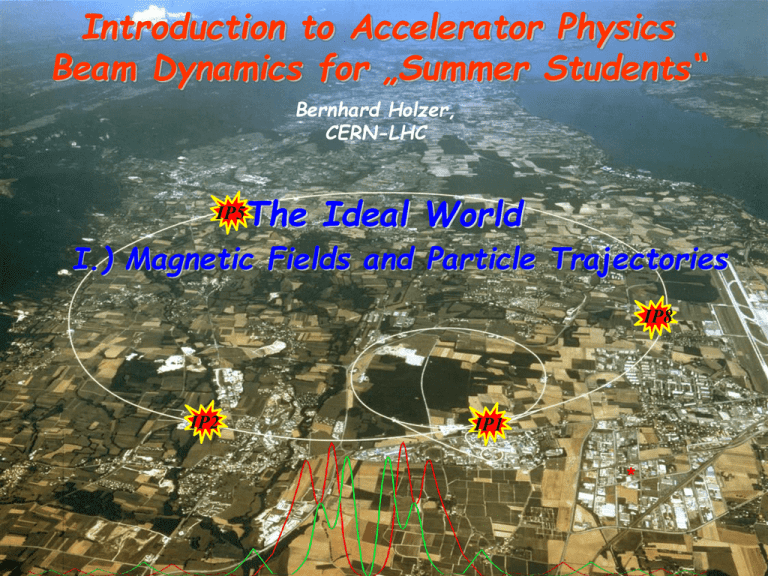
Introduction to Accelerator Physics Beam Dynamics for „Summer Students“ Bernhard Holzer, CERN-LHC The Ideal World IP5 I.) Magnetic Fields and Particle Trajectories IP8 IP2 IP1 * Luminosity Run of a typical storage ring: LHC Storage Ring: Protons accelerated and stored for 12 hours distance of particles travelling at about v ≈ c L = 1010-1011 km ... several times Sun - Pluto and back intensity (1011) 3 - 2 1 - guide the particles on a well defined orbit („design orbit“) focus the particles to keep each single particle trajectory within the vacuum chamber of the storage ring, i.e. close to the design orbit. 1.) Introduction and Basic Ideas „ ... in the end and after all it should be a kind of circular machine“ need transverse deflecting force F q *( E v B) Lorentz force typical velocity in high energy machines: v c 3*108 m s Example: B 1T F q 3 108 F q 300 equivalent el. field ... m Vs 1 2 s m MV m E technical limit for el. field: E 1 MV m old greek dictum of wisdom: if you are clever, you use magnetic fields in an accelerator wherever it is possible. y The ideal circular orbit θ ρ ● s circular coordinate system condition for circular orbit: Lorentz force centrifugal force FL e v B Fcentr m0 v 2 m0 v 2 ev B p B e B ρ = "beam rigidity" 2.) The Magnetic Guide Field Dipole Magnets: B define the ideal orbit homogeneous field created by two flat pole shoes 0 n I h Normalise magnetic field to momentum: p B e 1 convenient units: eB p Vs B T 2 m GeV p c Example LHC: B 8. 3 T GeV p 7000 c 1 1 e 8.3 Vs 2 m 7000 *109 eV 0.333 8.3 1 7000 m c 8.3 s * 3 *108 m 7000 *109 m 2 s The Magnetic Guide Field ρ α ds field map of a storage ring dipole magnet 2.53 km rule of thumb: 2πρ = 17.6 km ≈ 66% 1 0.3 B T p GeV / c B 1 ... 8 T „normalised bending strength“ 2.) Focusing Properties – Transverse Beam Optics classical mechanics: pendulum there is a restoring force, proportional to the elongation x: d 2x m * 2 c * x dt general solution: free harmonic oszillation x(t ) A *cos(t ) Storage Ring: we need a Lorentz force that rises as a function of the distance to ........ ? ................... the design orbit F ( x) q * v * B ( x) Quadrupole Magnets: required: focusing forces to keep trajectories in vicinity of the ideal orbit linear increasing Lorentz force linear increasing magnetic field By g x Bx g y normalised quadrupole field: k simple rule: g p/e k 0.3 g (T / m ) p(GeV / c ) LHC main quadrupole magnet g 25 ... 220 T / m what about the vertical plane: ... Maxwell E B = j 0 t By Bx g x y Focusing forces and particle trajectories: normalise magnet fields to momentum (remember: B*ρ = p / q ) Dipole Magnet Quadrupole Magnet B B 1 p / q B g k : p/q 3.) The Equation of Motion: B( x ) 1 1 1 k x m x 2 n x 3 ... p/e 2! 3! only terms linear in x, y taken into account dipole fields quadrupole fields Separate Function Machines: Split the magnets and optimise them according to their job: bending, focusing etc Example: heavy ion storage ring TSR * man sieht nur dipole und quads linear ŷ The Equation of Motion: ● * Equation for the horizontal motion: x x ( * 1 2 k) 0 θ ρ y ● x s Equation for the vertical motion: 1 2 k 0 no dipoles … in general … k quadrupole field changes sign y k y 0 y x 4.) Solution of Trajectory Equations Define … hor. plane: … vert. Plane: K 1 2 k x K x 0 K k Differential Equation of harmonic oscillator … with spring constant K Ansatz: Hor. Focusing Quadrupole K > 0: x( s) x0 cos( K s) x0 x( s) x0 K sin( 1 sin( K s) K K s) x0 cos( K s) For convenience expressed in matrix formalism: x x M foc * x s1 x s 0 M foc cos K l K sin K l 1 sin K cos Kl K l s=0 s = s1 hor. defocusing quadrupole: x K x 0 Ansatz: Remember from school x(s) a1 cosh( s) a2 sinh( s) M defoc cosh Kl 1 sinh K K sinh Kl cosh K l K l drift space: K=0 x(s) x 0 *s ! 1 l M drift 0 1 with the assumptions made, the motion in the horizontal and vertical planes are independent „ ... the particle motion in x & y is uncoupled“ Transformation through a system of lattice elements combine the single element solutions by multiplication of the matrices focusing lens M total M QF * M D * M QD * M Bend * M D*..... x x M(s2,s1 ) * x's2 x's1 dipole magnet defocusing lens court. K. Wille in each accelerator element the particle trajectory corresponds to the movement of a harmonic oscillator „ x(s) 0 typical values in a strong foc. machine: x ≈ mm, x´ ≤ mrad s 5.) Orbit & Tune: Tune: number of oscillations per turn 64.31 59.32 Relevant for beam stability: non integer part LHC revolution frequency: 11.3 kHz 0.31*11.3 3.5kHz LHC Operation: Beam Commissioning First turn steering "by sector:" One beam at the time Beam through 1 sector (1/8 ring), correct trajectory, open collimator and move on. Question: what will happen, if the particle performs a second turn ? ... or a third one or ... 1010 turns x 0 s II.) The Ideal World: Particle Trajectories, Beams & Bunches Bunch in a Storage Ring ( Z X Y) Astronomer Hill: differential equation for motions with periodic focusing properties „Hill‘s equation“ Example: particle motion with periodic coefficient equation of motion: x( s ) k ( s ) x( s ) 0 restoring force ≠ const, k(s) = depending on the position s k(s+L) = k(s), periodic function we expect a kind of quasi harmonic oscillation: amplitude & phase will depend on the position s in the ring. 6.) The Beta Function „it is convenient to see“ ... after some beer ... general solution of Mr Hill can be written in the form: Ansatz: x(s) * (s) *cos( (s) ) ε, Φ = integration constants determined by initial conditions β(s) periodic function given by focusing properties of the lattice ↔ quadrupoles ( s L) ( s ) ε beam emittance = woozilycity of the particle ensemble, intrinsic beam parameter, cannot be changed by the foc. properties. scientifiquely spoken: area covered in transverse x, x´ phase space … and it is constant !!! Ψ(s) = „phase advance“ of the oscillation between point „0“ and „s“ in the lattice. For one complete revolution: number of oscillations per turn „Tune“ Qy 1 ds 2 ( s) 7.) Beam Emittance and Phase Space Ellipse ( s)* x 2 ( s) 2 ( s) x( s) x( s) ( s) x( s) 2 x´ ● Liouville: in reasonable storage rings area in phase space is constant. ● A = π*ε=const ● ● ● ● x x(s) s ε beam emittance = woozilycity of the particle ensemble, intrinsic beam parameter, cannot be changed by the foc. properties. Scientifiquely spoken: area covered in transverse x, x´ phase space … and it is constant !!! Particle Tracking in a Storage Ring Calculate x, x´ for each linear accelerator element according to matrix formalism plot x, x´as a function of „s“ ● … and now the ellipse: note for each turn x, x´at a given position „s1“ and plot in the phase space diagram Emittance of the Particle Ensemble: ( Z X Y) Emittance of the Particle Ensemble: x(s) (s) cos((s) ) xˆ (s) (s) Gauß Particle Distribution: ( x) N e e 2 x particle at distance 1 σ from centre ↔ 68.3 % of all beam particles single particle trajectories, N ≈ 10 11 per bunch LHC: 180 m 5 *1010 m rad * 5 *10 10 m *180 m 0.3 mm aperture requirements: r 0 = 12 * σ 1 x2 2 x2 III.) The „not so ideal“ World Lattice Design in Particle Accelerators x, y D 1952: Courant, Livingston, Snyder: Theory of strong focusing in particle beams Recapitulation: ...the story with the matrices !!! Equation of Motion: x K x 0 Solution of Trajectory Equations K 1 2 k … hor. plane: K k x x M * x s1 x s 0 … vert. Plane: 1 l M drift 0 1 M foc M defoc cos( K l ) K sin( K l ) cosh( K l ) K sinh( K l ) K l) K cos( K l ) 1 sin( K l) K cosh( K l ) 1 sinh( M total M QF * M D * M B * M D * M QD * M D * ... 8.) Lattice Design: „… how to build a storage ring“ Geometry of the ring: B * p / e p = momentum of the particle, ρ = curvature radius Bρ= beam rigidity Circular Orbit: bending angle of one dipole ds dl Bdl B The angle run out in one revolution must be 2π, so for a full circle Bdl 2 B p Bdl 2 q … defines the integrated dipole field around the machine. Example LHC: 7000 GeV Proton storage ring dipole magnets N = 1232 l = 15 m q = +1 e B dl N l B 2 p/e 2 7000 109 eV B 8.3 Tesla m 1232 15 m 3 108 e s FoDo-Lattice A magnet structure consisting of focusing and defocusing quadrupole lenses in alternating order with nothing in between. (Nothing = elements that can be neglected on first sight: drift, bending magnets, RF structures ... and especially experiments...) Starting point for the calculation: in the middle of a focusing quadrupole Phase advance per cell μ = 45°, calculate the twiss parameters for a periodic solution 9.) Insertions x, y D β-Function in a Drift: ( ) 0 2 l l 0 * β0 At the end of a long symmetric drift space the beta function reaches its maximum value in the complete lattice. -> here we get the largest beam dimension. -> keep l as small as possible 7 sima beam size iside a mini beta quadrupole ... unfortunately ... in general ... clearly there is another problem !!! high energy detectors that are installed in that driftatspaces Example: Luminosity optics LHC: β* = 55 cm arefor a little bit bigger centimeters smallest βmax wethan haveatofew limit the overall...length and keep the distance “s” as small as possible. The Mini-β Insertion: R L * react production rate of events is determined by the cross section Σreact and a parameter L that is given by the design of the accelerator: … the luminosity I1 * I 2 1 L * * 2 4 e f 0 b x * * y 10.) Luminosity p2-Bunch 10 11 particles p1-Bunch IP 10 11 ±σ particles Example: Luminosity run at LHC x , y 0.55 m f 0 11.245 kHz x , y 5 10 10 rad m nb 2808 x , y 17 m I p 584 mA L 1.0 1034 1 cm 2 s I p1 I p 2 1 L * 2 4e f 0 nb x y Mini-β Insertions: Betafunctions A mini-β insertion is always a kind of special symmetric drift space. greetings from Liouville / x´ the smaller the beam size the larger the bam divergence ● ● ● ● ● ● x Mini-β Insertions: some guide lines * calculate the periodic solution in the arc * introduce the drift space needed for the insertion device (detector ...) * put a quadrupole doublet (triplet ?) as close as possible * introduce additional quadrupole lenses to match the beam parameters to the values at the beginning of the arc structure parameters to be optimised & matched to the periodic solution: 8 individually powered quad magnets are needed to match the insertion ( ... at least) x , x y, y Dx , Dx Qx , Qy IV) … let´s talk about acceleration Electrostatic Machines (Tandem –) van de Graaff Accelerator creating high voltages by mechanical transport of charges * Terminal Potential: U ≈ 12 ...28 MV using high pressure gas to suppress discharge ( SF6 ) Problems: * Particle energy limited by high voltage discharges * high voltage can only be applied once per particle ... ... or twice ? * The „Tandem principle“: Apply the accelerating voltage twice ... ... by working with negative ions (e.g. H-) and stripping the electrons in the centre of the structure Example for such a „steam engine“: 12 MV-Tandem van de Graaff Accelerator at MPI Heidelberg 12.) Linear Accelerator Energy Gain per „Gap“: 1928, Wideroe + -̶ + -̶ + -̶ + W q U 0 sin RF t drift tube structure at a proton linac (GSI Unilac) 500 MHz cavities in an electron storage ring * RF Acceleration: multiple application of the same acceleration voltage; brillant idea to gain higher energies 13.) The Acceleration Where is the acceleration? Install an RF accelerating structure in the ring: E c z B. Salvant N. Biancacci 14.) The Acceleration for Δp/p≠0 “Phase Focusing” ideal particle particle with Δp/p < 0 particle with Δp/p > 0 below transition faster slower Focussing effect in the longitudinal direction keeping the particles close together ... forming a “bunch” oscillation frequency: f s f rev h s qU 0 cos s * 2 Es ≈ some Hz ... so sorry, here we need help from Albert: E total2 mc 1 v mc 2 1 2 c E v2 1 2 c v/c 1 0.9 0.8 0.7 0.6 0.5 0.4 0.3 ... some when the particles do not get faster anymore 0.2 0.1 .... but heavier ! 0 0 500 1000 1500 2000 2500 3000 3500 kinetic energy of a proton 4000 4500 5000 15.) The Acceleration for Δp/p≠0 “Phase Focusing” above transition ideal particle particle with Δp/p < 0 particle with Δp/p > 0 heavier lighter Focussing effect in the longitudinal direction keeping the particles close together ... forming a “bunch” ... and how do we accelerate now ??? with the dipole magnets ! The RF system: IR4 S34 ACS ACS S45 ADT D3 D4 Q5 Q6 Q7 B2 420 mm 194 mm B1 ACS ACS Bunch length (4) ns 1.06 Energy spread (2) 10-3 0.22 Synchr. rad. loss/turn keV Synchr. rad. power kW 3.6 RF frequency M Hz 400 Harmonic number 4xFour-cavity cryo module 400 MHz, 16 MV/beam Nb on Cu cavities @4.5 K (=LEP2) Beam pipe diam.=300mm 7 35640 RF voltage/beam MV 16 Energy gain/turn keV 485 Synchrotron frequency Hz 23.0 LHC Commissioning: RF ( Z X Y) a proton bunch: focused longitudinal by the RF field ~ 200 turns Bunch length ~ 1.5 ns ~ 45 cm RF off RF on, phase optimisation RF on, phase adjusted, beam captured Problem: panta rhei !!! (Heraklit: 540-480 v. Chr.) ( Z X Y) Bunch length of Electrons ≈ 1cm just a stupid (and nearly wrong) example) U0 t 500 MHz c 60 cm 60 cm sin( 90o ) 1 sin( 84o ) 0.994 U 6.0 10 3 U typical momentum spread of an electron bunch: p 1.0 103 p 17.) Dispersion and Chromaticity: Magnet Errors for Δp/p ≠ 0 Influence of external fields on the beam: prop. to magn. field & prop. zu 1/p dipole magnet B dl focusing lens k p/e x D ( s ) D( s ) p p g p e particle having ... to high energy to low energy ideal energy Dispersion Example: homogeneous dipole field xβ Closed orbit for Δp/p > 0 xβ . ρ xi ( s) D( s) Matrix formalism: x( s) x ( s) D( s) p p x( s) C ( s) x0 S ( s) x0 D( s) p p x C S x p D x C S x p s 0 D 0 p p or expressed as 3x3 matrix x C S D x x C S D x p p 0 0 1 p p s 0 D Example x 1...2 mm D( s ) 1...2 m p 1 103 p Amplitude of Orbit oscillation contribution due to Dispersion ≈ beam size Dispersion must vanish at the collision point Calculate D, D´: ... takes a couple of sunny Sunday evenings ! ! V.) Are there Any Problems ??? sure there are Some Golden Rules to Avoid Trouble I.) Golden Rule number one: do not focus the beam ! (s) * Problem: Resonances x co (s) Assume: Tune = integer Qualitatively spoken: 1 s1 * cos( s1 s Q) ds s1 Q 1 2sin Q 0 Integer tunes lead to a resonant increase of the closed orbit amplitude in presence of the smallest dipole field error. Tune and Resonances m*Qx+n*Qy+l*Qs = integer Tune diagram up to 3rd order Qy =1.5 … and up to 7th order Qy =1.3 Homework for the operateurs: find a nice place for the tune where against all probability the beam will survive Qy =1.0 Qx =1.0 Qx =1.3 Qx =1.5 II.) Golden Rule number two: Never accelerate charged particles ! Fdef Transport line with quadrupoles x K(s)x 0 Transport line with quadrupoles and space charge x (K(s) K SC (s))x 0 2r I x K(s) 2 03 3 x 0 ea β γ c KSC Golden Rule number two: Never accelerate charged particles ! Q x, y Tune Shift due to Space Charge Effect Problem at low energies r0 N 2x, y 2 v/c 1 0.9 0.8 0.7 0.6 0.5 0.4 0.3 ... at low speed the particles repel each other 0.2 0.1 0 0 1000 2000 Linac 2 Ekin=60 MeV Linac 4 Ekin=150 MeV 3000 4000 5000 Ekin of a proton III.) Golden Rule number three: Never Collide the Beams ! 25 ns the colliding bunches influence each other change the focusing properties of the ring !! most simple case: linear beam beam tune shift x* * rp * N p Qx 2 p ( x y ) * x Qx and again the resonances !!! Courtesy W. Herr Qx IV.) Golden Rule Number four: Never use Magnets “effective magnetic length” lmag B * leff Bds 0 Clearly there is another problem ... ... if it were easy everybody could do it Again: the phase space ellipse for each turn write down – at a given position „s“ in the ring – the x x single partilce amplitude x M turn * and the angle x´... and plot it. x s1 x s 0 ● A beam of 4 particles – each having a slightly different emittance: Installation of a weak ( !!! ) sextupole magnet The good news: sextupole fields in accelerators cannot be treated analytically anymore. no equatiuons; instead: Computer simulation „ particle tracking “ ● Effect of a strong ( !!! ) Sextupole … Catastrophy ! ● „dynamic aperture“ Golden Rule XXL: COURAGE and with a lot of effort from Bachelor / Master / Diploma / PhD and Summer-Students the machine is running !!! thank’x for your help and have a lot of fun

