Proceedings of the Twenty-Third International Conference on Automated Planning and Scheduling
Planning Solar Array Operations on the International Space Station
Jeremy Frank
NASA Ames Research Center
Mail Stop N269-3
Moffett Field, California 94035-1000
Introduction
0
359
SARJ Port 73
Flight controllers manage the orientation and modes of eight
large solar arrays that power the International Space Station (ISS). The task requires generating plans that balance
complex constraints and preferences. These considerations
include context-dependent constraints on viable solar array
configurations, temporal limits on transitions between configurations, and preferences on which considerations have
priority. The Solar Array Constraint Engine (SACE) treats
this operations planning problem as a sequence of tractable
constrained optimization problems. SACE uses constraint
management and automated planning capabilities to reason
about the constraints, to find optimal array configurations
subject to these constraints and solution preferences, and to
automatically generate solar array operations plans.
SACE is built on the Extensible Universal Remote Operations Planning Architecture (EUROPA) model-based planning system. EUROPA facilitated SACE development by
providing model-based planning, built-in constraint reasoning capability, and extensibility. EUROPAs built-in functionality was used to model some constraints, while EUROPAs modular and extensible framework enabled the addition of custom code for modeling other constraints and
optimizations, as well as the addition of custom planning
algorithms to generate solar array plans.
SACE is currently in use at the NASA Johnson Space
Center (JSC) for monitoring ISS solar arrays; the planning
functionality is being certified for operational use. SACE
reduces a highly manual process that takes weeks to an automated process that takes tens of minutes. In addition,
SACE provides flight controllers with a real-time situational
awareness capability by monitoring the status of the various
constraints as the plans are executed. Flight controllers can
also perform what-if analysis in SACE to address unplanned
events that may cause station configuration changes. This
article formulates the planning problem, explains how EUROPA solves the problem, and provides performance statistics from several planning scenarios. This paper summarizes
the key aspects of the problem and its solution; for more information please refer to (Reddy et al. 2011).
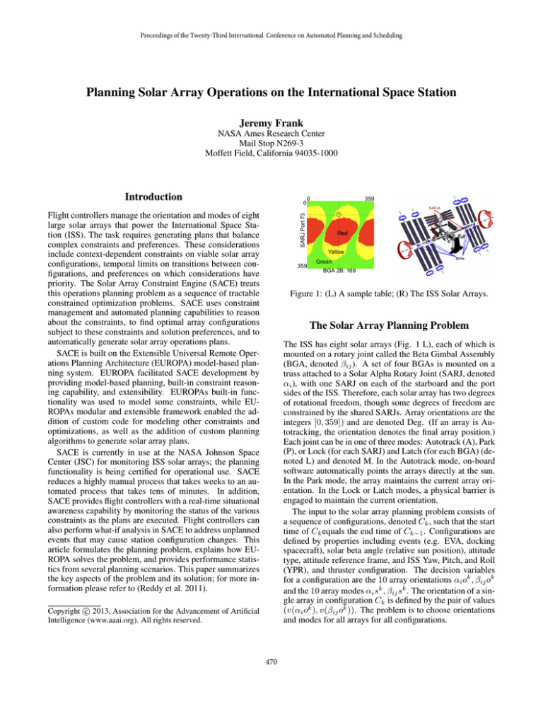
0
Red
Yellow
359
Green
BGA 2B: 169
Figure 1: (L) A sample table; (R) The ISS Solar Arrays.
The Solar Array Planning Problem
The ISS has eight solar arrays (Fig. 1 L), each of which is
mounted on a rotary joint called the Beta Gimbal Assembly
(BGA, denoted βij ). A set of four BGAs is mounted on a
truss attached to a Solar Alpha Rotary Joint (SARJ, denoted
αi ), with one SARJ on each of the starboard and the port
sides of the ISS. Therefore, each solar array has two degrees
of rotational freedom, though some degrees of freedom are
constrained by the shared SARJs. Array orientations are the
integers [0, 359]) and are denoted Deg. (If an array is Autotracking, the orientation denotes the final array position.)
Each joint can be in one of three modes: Autotrack (A), Park
(P), or Lock (for each SARJ) and Latch (for each BGA) (denoted L) and denoted M. In the Autotrack mode, on-board
software automatically points the arrays directly at the sun.
In the Park mode, the array maintains the current array orientation. In the Lock or Latch modes, a physical barrier is
engaged to maintain the current orientation.
The input to the solar array planning problem consists of
a sequence of configurations, denoted Ck , such that the start
time of Ck equals the end time of Ck−1 . Configurations are
defined by properties including events (e.g. EVA, docking
spacecraft), solar beta angle (relative sun position), attitude
type, attitude reference frame, and ISS Yaw, Pitch, and Roll
(YPR), and thruster configuration. The decision variables
for a configuration are the 10 array orientations αi ok , βij ok
and the 10 array modes αi sk , βij sk . The orientation of a single array in configuration Ck is defined by the pair of values
(v(αi ok ), v(βij ok )). The problem is to choose orientations
and modes for all arrays for all configurations.
c 2013, Association for the Advancement of Artificial
Copyright Intelligence (www.aaai.org). All rights reserved.
470
Constraints
and solved offline. The 12 LP variables arise from the
three colors (R,Y,G) combined with the four table types
(P,L,S,E). The LP constraint enforcing the trade preferring
green environment for no worse than yellow power is
written wGP + wY E ≥ wY P + wGE + 1. The sum of these
variables is minimized in the LP (lower color costs are prek
k
ferred.)
P The color cost Lc (Ck ,kv(αi o ),kv(βij o )) reduces
to t∈T (Ck ) wr,s |r = t(v(αi o )v(βij o )), s = Y (t). We
omit discussion of the other optimization critiera.
There are four classes of constraints that limit orientations:
power generation (denoted P), structural load (L), environmental contamination due to particulate accumulation on array surfaces (E), and longeron shadowing (S). These constraints are represented by tables (denoted t) mapping an orientation to a color from the set red (R), yellow (Y), and green
(G) (Fig 1 R). One table of each type constrains the orientation and mode in each configuration. The class of table t is
denoted Y (t). A separate row, column and cell maintain entries in the event the SARJ is autotracking, the BGA is autotracking, or both arrays are autotracking, respectively. Thus,
a table t : Deg 2 → Col (the set of colors). In most cases,
red indicates infeasibility, for example, insufficient power to
run life support or forces strong enough to cause structural
damage to the station; yellow values are acceptable but may
result in a reduction of vehicle longevity or achievable mission objectives, and green is optimal.
The tables contain headers that specify the properties of
the configurations required for the tables to apply. Thus,
each table is a conditional constraint. Denote by T (Ck ) the
set of applicable tables in configuration Ck . Each configuration Ck identifies one of each class of table constraint.
The tables T (Ck ) constrain the mode variables
αi sk , βij sk by means of a set of Lock-Latch constraints
denoted LLC. A fragment of the LLC logic follows: ”In
determining a mode, prefer Autotrack to Park, and Park to
Latch or Lock. If the current orientations are safe, but if
there is a possibility of the loads on any joint getting into
yellow zone (as per constraint table L) during autotracking,
park that joint, and if there is possibility of loads getting
into red zone (as per L), lock or latch that joint. Further, if
there is a possibility of the contamination constraints getting
into the red zone (as per E) during Autotracking, avoid
Autotrack, except during contingency operations.” Since
the tables are uniquely determined by the configuration,
LLCk (αi ok , βij ok αi sk , βij sk ) constrains all the modes
and orientations on one side of ISS for configuration Ck .
During configuration Ck arrays must be in one of the
modes, or transitioning between modes, both by commanding (e.g. Parking or Unlocking) or by turning the arrays.
Each array type (SARJ and BGA) has a maximum rate at
which the different joints can be slewed or turned. The BGA
slew rate dβij is 18◦ /min while the SARJ rate dαi defaults
to 9◦ /min but is adjustable up to 30◦ /min (the SARJ rate is
fixed over the course of a plan).
Planning and Optimization
SACE optimizes configurations sequentially, constraining
the solution of subsequent configurations based on the solution of previous configurations. Conflicts may arise because
there is insufficient time for actions to switch between optimal solutions for the adjacent configurations. There is no
backtracking, and hence there is no guarantee that a feasible
solution is found even if one exists. However, SACE users
find that most conflicts can be resolved by merging conflicting configurations, and finding a single solution that works
for all merged configurations. Optimization of a merged
configuration requires selecting the worst color from all tables that apply to any ’parent’ configuration for the purposes
of computing color cost, mode cost, and evaluating LLC.
While optimizing each array orientation and mode requires
searching a complex optimization landscape over the domain of 360 × 360 possibilities, this cost is constant for a
single configuration. The planning algorithm is:
for each configuration Ck in increasing start time order
Optimize array orientation (for each SARJ separately)
Compute Array Modes
if Optimal solution for Ck conflicts with Ck−1
Merge configurations Ck and Ck−1
Optimize array orientation for new configuration
Compute Array Modes
Prune array positions for Ck+1 using slew rates and orientation
for each configuration Ck in increasing start time order
Eliminate Re-Lock / Re-Latch
Insert Turns and Mode Change States
Implementation
SACE is built on top of the EUROPA planning system.
Each configuration is modeled as a state on a configuration timeline. Each array has a timeline of states including Autotrack, Park, Lock or Latch, Turning, and model
change states. Compatibilities describe allowed state transitions. EUROPA’s customizable constraint engine was extended to represent the table constraints, the lock latch constraints, propagation algorithms, and the optimizing search
algorithms required by the application.
Optimization Criteria
The
lar
P
optimization
criteria
for
a
soarray
plan
is
L(Ck , αi )
=
k
k
k
k
where
v∈c,m,d,t,p wv Lv (Ck , αi o , βij o αi s , βij s )
c is the color cost, m is the mode cost, d is the direction
change cost, t is the array angular distance cost, and p is the
power cost, in order of decreasing importance. We describe
the color cost in more detail in this section. Table color
tradeoffs are permitted; for instance, an orientation that
sacrifices green power for green environment is preferred.
These preferences were transformed into a Linear Program
References
Reddy, S.; Frank, J.; Iatauro, M.; Kurklu, E.; Boyce, M. E.;
Frank, J.; Ai-Chaing, M.; and Jónsson, A. 2011. Planning solar array operations on the international space station.
ACM Transactions on Intelligent Systems 2(4).
471


