Proceedings of the Twenty-Fifth International Florida Artificial Intelligence Research Society Conference
R-One Swarm Robot:
Developing the Accelerometer and Gyroscope
Ebrima Jobe1, James McLurkin2, and Chutima Boonthum-Denecke1
1
Hampton University, Hampton, VA, 23668 USA
2
Rice University, Houston, TX 77005 USA
ebrima.jobe92@gmail.com, jmclurkin@rice.edu, chutima.boonthum@gmail.com
it should also to be reasonably low in cost with high
performance and easily interfaced to a MCU (MicroController Unit). Some of the other solutions are
prohibitively expensive, even if they may work well.
The solution we had in mind had to be fairly small and
use up little space and little power. Hence, ADXRS150
(Bartolini, 2005) and ADXRS300 gyroscopes are our pick
to low cost and low power with high performance. The
gyro is very small at about 5mm square (or 0.3 inches
square). The robots have 3D gyro and 3D accelerometers.
The plastic skirt actually floats atop the bottom circuit
board that has switches that detect contact with an object.
Abstract
Mobile robots are becoming more relevant and an essential
part of our everyday lives. They are increasingly taking their
place in service oriented applications including domestic
and entertainment roles. They are beginning to open up
many potential opportunities, but they still come with
challenges in terms of their limited sensing capability and
accuracy. In this project, we addressed these fundamental
problems with mobile robotics and demonstrate our
approach to each of the problems with a mobile robot
equipped with low cost and low end devices. The r one
swarm robot is a low cost multi robot systems platform that
is advanced enough for multi robot research, robust enough
for undergraduate and graduate education and cheap enough
for K 12 outreach. As robots become more and more useful,
multiple robots working together on a single task will
become commonplace. Many of the most useful
applications of robots are particularly well suited to this
“swarm” approach. Groups of robots can perform these
tasks more efficiently, and can perform them in
fundamentally different ways than robots working
individually. However, swarms of robots are difficult to
program and coordinate.
Introduction
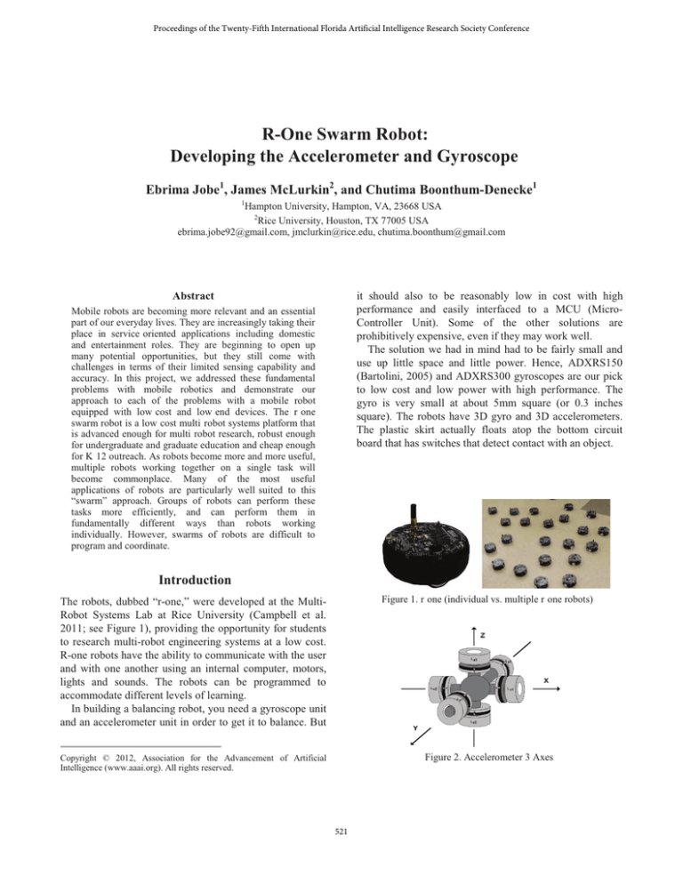
The robots, dubbed “r-one,” were developed at the MultiRobot Systems Lab at Rice University (Campbell et al.
2011; see Figure 1), providing the opportunity for students
to research multi-robot engineering systems at a low cost.
R-one robots have the ability to communicate with the user
and with one another using an internal computer, motors,
lights and sounds. The robots can be programmed to
accommodate different levels of learning.
In building a balancing robot, you need a gyroscope unit
and an accelerometer unit in order to get it to balance. But
Figure 1. r one (individual vs. multiple r one robots)
Copyright © 2012, Association for the Advancement of Artificial
Intelligence (www.aaai.org). All rights reserved.
Figure 2. Accelerometer 3 Axes
521
data is being clocked out, new data is clocked in. Early on,
we come across Code Composer Studio, an integrated
development environment for processors such as the
MSP430, from Texas Instruments. Microcode, a layer of
hardware-level instructions involved in the implementation
of higher level machine code instructions, is written in the
C programming language. Code Composer Studio
basically opens the doors for a programmer to experience
real-time coding and actual debugging to solve errors.
When we first discovered this, we went step-by-step in the
code and checked the oscilloscope, a type of electronic test
instrument that allows observation of constantly varying
signal voltages.
SPI is a Data Exchange protocol. As data is being
clocked out, new data is also being clocked in. When one
“transmits” data, the incoming data must be read before
attempting to transmit again. If the incoming data is not
read, then the data will be lost and the SPI module may
become disabled as a result. Always read the data after a
transfer has taken place, even if the data has no use in your
application. Data is always “exchanged” between devices.
No device can just be a “transmitter” or just a “receiver” in
SPI. However, each device has two data lines, one for
input and one for output. These data exchanges are
controlled by the clock line, SCK, which is controlled by
the master device.
In order to start building our necessary setup for the
Serial Peripheral Interface to initiate, we connected lines
from a device on the circuit board, like an accelerometer,
to the MSP430 microcontroller, and then connecting them
back to an oscilloscope. An oscilloscope reading can tell
you whether or not lines are communicating, and if so, you
can figure out what data is being sent and received.
Figure 3 shows the oscilloscope reading, each line
represents four signals: clock (SCLK), master output/slave
input (MOSI), master input/slave output (MISO), slave
select (SS). Three signals are shared by all devices on the
SPI bus: SCLK, MOSI and MISO. SCLK is generated by
the master device and is used for synchronization. MOSI
and MISO are the data lines. The direction of transfer is
indicated by their names. Data is always transferred in both
directions in SPI, but an SPI device interested in only
transmitting data can choose to ignore the receive bytes.
Likewise, a device only interested in the incoming bytes
can transmit dummy bytes.
The Hypothesis
For a robot such as this to perform efficiently, as well as
keeping it balanced, the ability for the robot to understand
its surroundings is absolutely necessary. An accelerometer
is an electromechanical device used to measure the tilt of
an object in 3 different axes (see Figure 2). These forces
may be static, like the constant force of gravity pulling at
your feet, or they could be dynamic - caused by moving or
vibrating the accelerometer. By measuring the amount of
static acceleration due to gravity, you can find out the
angle the device is tilted at with respect to the earth. By
sensing the amount of dynamic acceleration, you can
analyze the way the device is moving. At first, measuring
tilt and acceleration doesn’t seem all that exciting.
However, engineers have come up with many ways to
make really useful products using them. An accelerometer
can help your project understand its surroundings better. Is
it driving uphill? Is it going to fall over when it takes
another step? Is it flying horizontally or is it dive bombing
your professor? A good programmer can write code to
answer all of these questions using the data provided by an
accelerometer. For example, an accelerometer can help
analyze problems in a car engine using vibration testing.
The gyroscope has the capability of measuring the rate
of rotation. This is important to the robot because it
provides a sense of direction and also helps understand its’
surroundings. The gyroscope demonstrates the earth’s
rotation. A freely rotating disk, called a rotor, was mounted
on a spinning axis in the center of a larger, stable wheel.
As the earth spun on its axis, the stable wheel rotated with
it, but the rotor did not move. The movement of the
mounted wheel followed the rotation of the earth, rotating
around the center disk and demonstrating the earth’s spin.
The gyroscope creates a range of guidance and
stabilization systems such as those used in airplanes and
submarines.
The Tasks
We were assigned the task with writing the software that
would handle data values coming from the accelerometer
and gyroscope from one circuit board to another. Serial
Peripheral Interface, also known as SPI (Microchip, n.d.),
is used to communicate data to and from the
microcontroller (computer chip) on the motherboard.
Below is a graph from an oscilloscope displaying the
signal voltages over SPI. Each line represents a different
signal on the robot which all work together to transfer data
through bits. SPI is a synchronous protocol that allows a
master device to communicate with a slave device
(accelerometer or gyroscope) through clock signals. When
data is exchanged between these devices, the clock signal
is provided by the master to provide synchronization. As
Figure 3. Oscilloscope Reading
522
In this poster, we will present the work that was
accomplished in developing the accelerometer and
gyroscope on the Rice University R-one Swarm Robot.
Acknowledgement
This research was supported in part by the National
Science Foundation (CNS-1042466) and various corporate
partners. Any opinions, findings, and conclusions or
recommendations expressed in this material are those of
the authors and do not necessarily reflect the views of the
NSF or our corporate partners.
References
Bartolini, D. 2005. Analog devices ADXRS 150 angular rate
sensing gyroscope. Sensor Workshop at ITP, Fall 2005.
http://itp.nyu.edu/physcomp/sensors/Reports/ADXRS150
Campbell, E, Kong ZC, Hered W, Lynch AJ, O'Malley MK, and
McLurkin J. 2011. Design of a low cost series elastic actuator for
multi robot manipulation. Proceeding of the 2011 IEEE
International Conference on Robotics and Automation (ICRA),
May 2011. http://dx.doi.org/10.1109/ICRA.2011.5980534
Microchip. N.d. Overview and Use of the PICmicro Serial
Peripheral Interface. http://ww1.microchip.com/downloads/en/
DeviceDoc/spi.pdf
523


