Applied Mechanics and Materials Vols. 204-208 (2012) pp 4418-4421
Online available since 2012/Oct/26 at www.scientific.net
© (2012) Trans Tech Publications, Switzerland
doi:10.4028/www.scientific.net/AMM.204-208.4418
A New Model of Orthotropic Bodies
Jiang Ke
School of Civil Engineering and Architecture, Shaanxi University of Technology,
Hanzhong, shaanxi, 723001, China
kj5525@sina.com
Keywords: Elasticity, new model, orthotropic body, truss, generalized Hooke's law
Abstract. The solution of linearly elastic and orthotropic solid bodies is very complicated, thus a new
element model for solving linearly elastic and orthotropic bodies is presented by using the generalized
Hooke's law and the superposition principle. This new model is a simple truss consisting of some
bars, and then the solution of orthotropic body becomes simple. Furthermore, this new model reveals
the physical mechanism of a solid body under the action of applied forces.
Introduction
In the field of solid mechanics, a method of solving problems in isotropic and linear elasticity by
means of a lattice analogy was presented by Hrenikoff at the University of British Colombia in
Vancouver in 1941 and by McHenry at the U.S. Bureau of Reclamation in 1943. The solution of
linearly elastic and orthotropic solid bodies is very complicated due to some difficulties in
mathematics [1-8]. Based on the generalized Hooke's law and the superposition principle, a new
element model of isotropic and linearly elastic solid bodies is presented in the literature [9]. The paper
will extend the new element model to orthotropic materials.
New Model
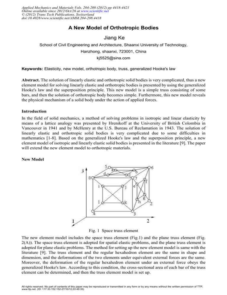
Fig. 1 Space truss element
The new element model includes the space truss element (Fig.1) and the plane truss element (Fig.
2(A)). The space truss element is adopted for spatial elastic problems, and the plane truss element is
adopted for plane elastic problems. The method for setting up the new element model is same with the
literature [9]. The truss element and the regular hexahedron element are the same in shape and
dimension, and the deformations of the two elements under equivalent external forces are the same.
Moreover, the deformation of the regular hexahedron element under an external force obeys the
generalized Hooke's law. According to this condition, the cross-sectional area of each bar of the truss
element can be determined, and then the truss element model is set up.
All rights reserved. No part of contents of this paper may be reproduced or transmitted in any form or by any means without the written permission of TTP,
www.ttp.net. (ID: 117.33.152.152-27/10/12,03:49:35)
Applied Mechanics and Materials Vols. 204-208
4419
Space Truss Element
The space truss element (Fig. 1) consists of seventy-two bars, it is a symmetric model, and the moduli
of elasticity of all bars are all E1 (Young's modulus in the 1-direction). The dimensions in the 1-, 2-,
and 3-directions of the space truss element are respectively: l1 = l 23 = l 67 = l 58 , l 2 = l 56 = l 87 = l 43 ,
l 3 = l 48 = l 37 = l 26 , where, l =length of bar, for example, l 23 is the length of bar 23, 2 and 3 being its
two endpoints. Moreover, l ad = l bc = m1l 1 , l ab = l cd = m1l 2 , l ef = l gh = m 2l 1 , l fg = l eh = m 2l 3 ,
l ij = l kl = m 3l 2 , l il = l jk = m 3l 3 , where, the ranges of values for m1 , m 2 and m 3 are all (0.01,0.99).
The bars including fifteen types with different cross-sectional areas:
A 1 = A 23 = A 67 = A 58 ,
A 2 = A 56 = A 87 = A 43 ,
A 3 = A 48 = A 37 = A 26 ,
A 4 = A 57 = A 68 ,
A 5 = A 27 = A 36 ,
A 6 = A 47 = A 38 ,
A 7 = A 5a = A 6b = A 7c = A 8d ,
A 8 = A 7e = A 6 f = A 2 g = A 3h ,
A 9 = A 8i = A 7 j = A 3 k = A 4 l ,
A10 = A ad = Abc ,
A11 = A ab = Acd ,
A12 = Aef = A gh ,
A13 = A fg = Aeh ,
A14 = A ij = A kl ,
A15 = A il = A jk .
where, A =cross-sectional area of bar, for example, A47 is the cross-sectional area of bar 47, 4 and 7
being its two endpoints.
According to the above method, the cross-sectional area of bar can be written as
A1 =
2
l 22l 32 (1 − v 23
E 2 / E 3 ) − l 12l 22 (v 13 + v 12v 23 ) − l 12l 32 (v 12 + v 13v 23E 2 / E 3 )
,
2
4l 2l 3 (1 − v 122 E 1 / E 2 − v 132 E 1 / E 3 − v 23
E 2 / E 3 − 2v 12v 13v 23E 1 / E 3 )
A2 =
l 12l 32 (1 − v 132 E 1 / E 3 )E 2 / E 1 − l 12l 22 (v 23E 2 / E 1 + v 12v 13 ) − l 22l 32 (v 12 + v 13v 23E 2 / E 3 )
,
2
4l 1l 3 (1 − v 122 E 1 / E 2 − v 132 E 1 / E 3 − v 23
E 2 / E 3 − 2v 12v 13v 23E 1 / E 3 )
A3 =
l 12l 22 (1 − v 122 E 1 / E 2 )E 3 / E 1 − l 12l 32 (v 23E 2 / E 1 + v 12v 13 ) − l 22l 32 (v 13 + v 12v 23 )
,
2
4l 1l 2 (1 − v 122 E 1 / E 2 − v 132 E 1 / E 3 − v 23
E 2 / E 3 − 2v 12v 13v 23E 1 / E 3 )
A4 =
l 3 (l 12 + l 22 )1.5 G 12
,
4l 1 l 2 E 1
A5 =
l 2 (l 12 + l 32 )1.5 G 31
,
4l 1 l 3 E 1
A6 =
l 1 (l 22 + l 32 )1.5 G 23
,
4l 2 l 3 E 1
v 12 + v 13v 23 E 2 / E 3
G 12 l 3 (l 12 + l 22 )1.5
A7 =
−
,
2
2
2
E
4l 1l 2
1
−
v
E
/
E
−
v
E
/
E
−
v
E
/
E
−
2
v
v
v
E
/
E
1
12 1
2
13 1
3
23 2
3
12 13 23 1
3
v 13 + v 12v 23
G 31 l 2 (l 12 + l 32 )1.5
A 8 =
−
,
2
2
2
4l 1l 3
1 − v 12 E 1 / E 2 − v 13 E 1 / E 3 − v 23 E 2 / E 3 − 2v 12v 13v 23 E 1 / E 3 E 1
v 23 E 2 / E 1 + v 12v 13
G 23 l 1 (l 22 + l 32 )1.5
A 9 =
−
,
2
2
2
4l 2 l 3
1 − v 12 E 1 / E 2 − v 13 E 1 / E 3 − v 23 E 2 / E 3 − 2v 12v 13v 23 E 1 / E 3 E 1
lA
l A
l A
A 10 = 2 1 72 0.5 ,
A 11 = 2 2 72 0.5 ,
A 12 = 2 1 82 0.5 ,
(l 1 + l 2 )
(l 1 + l 2 )
(l 1 + l 3 )
l A
l A
l A
A 13 = 2 3 82 0.5 ,
A 14 = 2 2 92 0.5 ,
A 15 = 2 3 92 0.5
(l 1 + l 3 )
(l 2 + l 3 )
(l 2 + l 3 )
(1)
4420
Progress in Industrial and Civil Engineering
where, E1, E2, E3= Young's moduli in the 1-, 2-, and 3-directions(Note that the 1-, 2-, and 3-directions
shown in Fig. 1 are three principal material directions), v ij =Poisson's ratio, i.e., the negative of the
transverse strain in the i-direction over the strain in the j-direction when stress is applied in the
j-direction, i.e., v ij = −ε i / ε j for σ = σ j and all other stresses are zero, G23, G31, G12=shear moduli in
the 2-3, 3-1, and 1-2 planes.
Plane Truss Element
Fig. 2 Plane truss element and its components
The plane truss element (Fig. 2(A)) is a rectangular truss consisting of fourteen bars, it is a symmetric
model, and its components are shown in Fig. 2(B) and Fig. 2(C). The moduli of elasticity of all bars
are E1 (Young's modulus in the 1-direction). The bars include six types with different cross-sectional
areas, i.e., A1 = A12 = A 43 , A 2 = A14 = A 23 , A 3 = A13 = A 24 , A 4 = A 1a = A 2b = A 3c = A 4d ,
A 5 = A ab = A cd , A 6 = A ad = A bc , where A is the cross-sectional area of bar. The dimensions in the
1-direction and 2-direction of the plane truss element are l1 = l 12 = l 43 , l 2 = l 14 = l 23 respectively,
where l is the length of bar. Moreover, l ab = l cd = m1l1 , l ad = l bc = m1l 2 , where, the range of value for
m1 is (0.01,0.99). Plane elastic problems include plane stress and plane strain problems, thus the
plane truss element model is set up for the two problems respectively, assuming that the direction of
thickness is in the 3-direction, and the thickness of solid body is h .
Plane Stress Problem. According to the above method, the cross-sectional area of bar can be
written as
(l 22 − v 12l12 )h
(l 12 E 2 / E 1 − v 12l 22 )h
A1 =
,
A
=
,
2
2(1 − v 122 E 1 / E 2 )l 2
2(1 − v 122 E 1 / E 2 )l1
v 12
G 12 h (l 12 + l 22 )1.5
A4 =
−
,
2
E
2l 1l 2
1
−
v
E
/
E
1
12 1
2
l A
l A
A 5 = 2 1 42 0.5 ,
A 6 = 2 2 24 0.5
(2)
(l 1 + l 2 )
(l 1 + l 2 )
Plane Strain Problem. According to the above method, the cross-sectional area of bar can be
written as
2
l 22 (1 − v 23
E 2 / E 3 ) − l 12 (v 12 + v 13v 23E 2 / E 3 )
A1 =
h ,
2
2(1 − v 122 E 1 / E 2 − v 132 E 1 / E 3 − v 23
E 2 / E 3 − 2v 12v 13v 23E 1 / E 3 )l 2
G 12 h (l 12 + l 22 )1.5
A3 =
,
2E 1l 1l 2
l 12 (1 − v 132 E 1 / E 3 )E 2 / E 1 − l 22 (v 12 + v 13v 23E 2 / E 3 )
A2 =
h ,
2
2(1 − v 122 E 1 / E 2 − v 132 E 1 / E 3 − v 23
E 2 / E 3 − 2v 12v 13v 23E 1 / E 3 )l 1
G 12 (l 12 + l 22 )1.5
A3 =
h ,
2E 1l 1l 2
Applied Mechanics and Materials Vols. 204-208
v 12 + v 13v 23 E 2 / E 3
G 12 (l 12 + l 22 )1.5
A 4 =
−
h ,
2
2
2
1 − v 12 E 1 / E 2 − v 13 E 1 / E 3 − v 23 E 2 / E 3 − 2v 12v 13v 23 E 1 / E 3 E 1 2l 1l 2
l A
l A
A 5 = 2 1 42 0.5 ,
A 6 = 2 2 24 0.5
(l 1 + l 2 )
(l 1 + l 2 )
4421
(3)
Method of solution
The method of solution by the new model is simple. A solid body is considered to consist of many
such truss elements, the neighboring truss elements being connected through their common nodes. In
this way, the solid body becomes a truss structure, its displacements can be obtained by calculating
this truss structure, and the stresses and strains of the solid body can be given by simple method. By
the way, the lengths of the twelve bars that are located at the centre of the space truss element are all
cl in the literature [9], the range of value for c is (0.01, 0.99), and the cross-sectional areas of the
twelve bars are all 3(4v − 1)l 2 /[8(1 + v )(1 − 2v )] .Using the new method and the finite element method
of Elasticity, some solid bodies have been analyzed, and the results of the two methods are in good
agreement.
Conclusions
The paper provides a truss element model for analyzing linearly elastic and orthotropic solid bodies,
and it is very simple. Furthermore, it is useful for understanding the physical mechanism of a solid
body under the action of applied forces.
References
[1] A. Samuelsson, O. C. Zienkiewicz, History of the stiffness method. International Journal for
Numerical Methods in Engineering, 2006, 67:149-157.
[2] S. Timoshenko, J. N. Goodier, Theory of Elasticity. McGraw-Hill Book Company, 1951.
[3] M. H. Sadd, Elasticity: Theory, Applications, and Numerics. Amsterdam: Elsevier Academic
Press, 2005.
[4] Zhilun Xu, Elasticity (4th ed.). Beijing: Higher Education Press, 2006 (in Chinese)
[5] Guanlin Shen, Gengkai Hu, Mechanics of Composite Materials. Beijing: Tsinghua University
Press, 2006 (in Chinese)
[6] Stephen W. Tsai, Composites design. Think Composites, 1987.
[7] R. M. Jones, Mechanics of Composite Materials (2nd ed.). Philadelphia, PA: Taylor & Francis,
1999.
[8] Autar K. Kaw, Mechanics of Composite Materials (2nd ed.). Boca Raton, FL: Taylor & Francis,
2006.
[9] Jiang Ke, "A new method for solving solid structures," Computational Mechanics: Proceedings
of ISCM2007, Beijing, China. Tsinghua University Press & Springer, pp. 508-514, July 2007.


