PADCAM: A Human-Centric Perceptual Interface for Temporal Recovery of
Pen-Based Input
Amay Champaneria
Larry Rudolph
Oxygen Research Group, MIT CSAIL
3230 Lori Ct., Belmont, CA 94002
amayc@alum.mit.edu
Oxygen Research Group, MIT CSAIL
32 Vassar St., 32-G868, Cambridge, MA 02139
rudolph@csail.mit.edu
Abstract
We present a perceptual interface for pen-based input that
uses live video of handwriting and recovers the time-ordered
sequence of strokes that were written. Our system employs
a novel algorithm for page detection and explores the use of
frame differencing and pen tracking to reconstruct the temporal information in the input video sequence. We present the
design and implementation of PADCAM, a working prototype
of the proposed pen-based input capture system, as well as
the preliminary results, which are very encouraging.
Introduction
In the PADCAM system, a small webcam focuses on what
a user writes on ordinary paper using an ordinary pen in order to capture the temporal and spacial strokes that would be
captured had the user been writing with a stylus on a touch
sensitive tablet. That is, for each blob of ink that is transferred to the page, its location on the page and the time it is
placed is recorded.
Obtaining this time information, a task known as temporal recovery, makes it easier to recognize the symbols represented by the pen strokes, which in turn makes it much easier to extract meaning from what was written or sketched.
PADCAM uses two different techniques for temporal recovery: ink tracking and pen tracking (Champaneria 2002); the
two are compared in this paper.
There are two obvious approaches to using computer vision for capturing the pen strokes made by a user. One
approach tracks the ink as it is applied to the paper by using a technique known as differencing. Differencing masks
out the pen, the hand, and any other non-ink markings and
then compares adjacent frames; the difference between two
frames is the ink that has just been applied. Yamasaki and
Hattori (Yamasaki & Hattori 1996) used a sequential differencing algorithm in the design of their data tablet system for
recognition of Japanese characters, This idea of using differences between frames was extended by Bunke et al (Bunke
et al. 1999), in their system for acquisition of cursive handwriting, They outline two challenges in the differential image approach: classification of differences to ignore pen and
hand movements and occlusion of existing ink traces. To
c 2004, American Association for Artificial IntelliCopyright gence (www.aaai.org). All rights reserved.
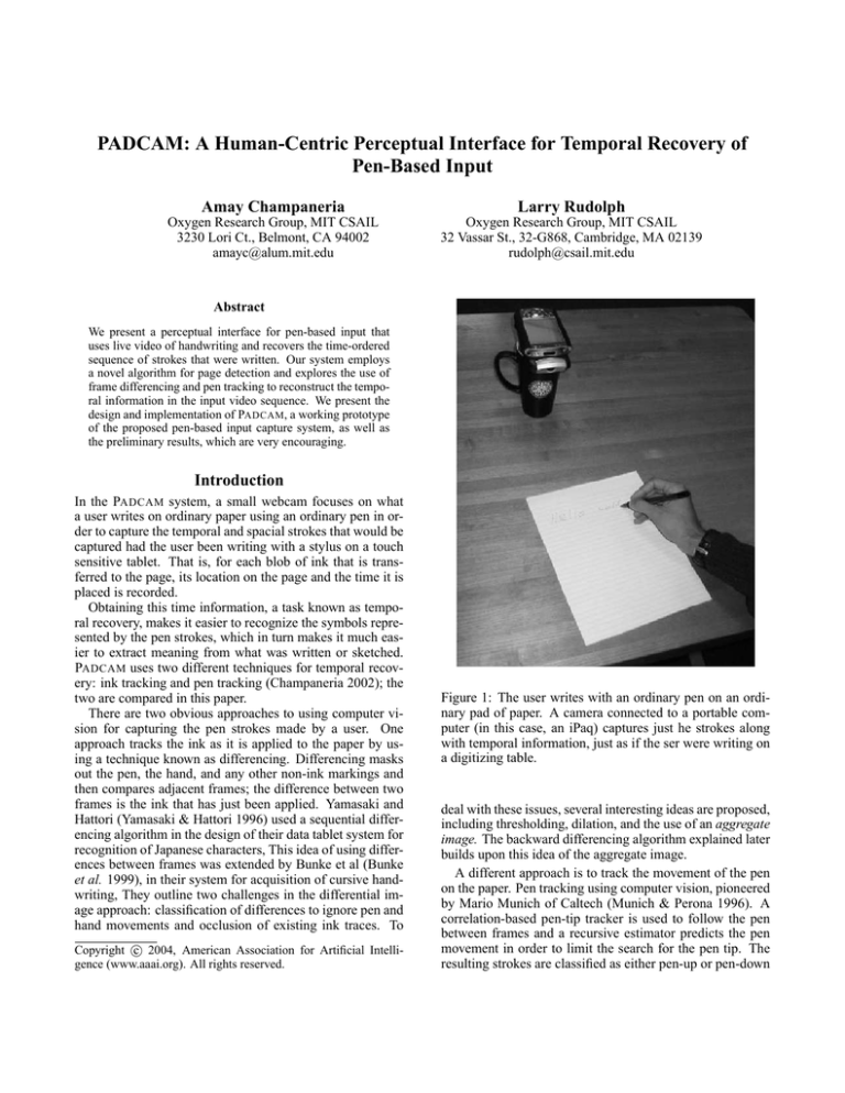
Figure 1: The user writes with an ordinary pen on an ordinary pad of paper. A camera connected to a portable computer (in this case, an iPaq) captures just he strokes along
with temporal information, just as if the ser were writing on
a digitizing table.
deal with these issues, several interesting ideas are proposed,
including thresholding, dilation, and the use of an aggregate
image. The backward differencing algorithm explained later
builds upon this idea of the aggregate image.
A different approach is to track the movement of the pen
on the paper. Pen tracking using computer vision, pioneered
by Mario Munich of Caltech (Munich & Perona 1996). A
correlation-based pen-tip tracker is used to follow the pen
between frames and a recursive estimator predicts the pen
movement in order to limit the search for the pen tip. The
resulting strokes are classified as either pen-up or pen-down
events using a Hidden Markov Model based on local ink
measurements. PADCAM uses the pen tracker and recursive
estimator, but employs its own simpler classifier for pen-up
and pen-down events.
The next section describes the details of PADCAM’s implementation of these two techniques. An experimental evaluation is then presented. The results are encouraging in that
reasonable accuracy is possible with minimal computation
overhead. The main overhead is image capture which is
easily addessed by a USB 2.0 or Firewire connection to the
camera. Pen tracking performs much better than ink tracking, but we postulate that combining the two will yield significantly better results.
Handwriting Capture and Recovery
Technically, the task is to capture pen-based input and recover the time-ordered sequence of strokes that were written. This task is achieved by sending video frames captured using a webcam through a pipeline of sequential stages
of processing, outlined in Figure 2. At a high-level, these
stages are roughly classified into pre-processing and temporal recovery. Ink tracking is presented before pen tracking.
Pre-Processing
In order to adapt to the user without making unreasonable assumptions about the writing utensil or environment,
our system requires an initialization phase during which it
gathers intelligence before attempting the temporal recovery task. Specifically, page detection, artifact elimination,
and tip acquisition must be performed. Although PADCAM
only does its pre-processing at the beginning, the usefulness
of the system would be improved if this step was performed
more frequently to handle cases when the camera or paper
are moved during the capture phase.
Page Detection Locating the writing surface, or page detection, is achieved using the following simple and intuitive
algorithm. First, Canny edge detection is performed on the
grayscale image, which effectively highlights the borders of
the page (Canny 1986). To compensate for camera and lighting noise, a subsequent dilation filter is applied, giving a
more stable signal. Next page borders are found using a
line-fitting Hough transform (Trucco & Verri 1998). The
intersections of these lines correspond to the corners of the
page. Once the corners are known and ordered, the system
calculates the perspective transform that will map each pixel
from the video frame to the virtual page image, which is
a view from directly above the writing surface. All subsequent operations are performed on the virtual page image,
so out-of-page artifacts are ignored and artifacts on the page
are easier to recognize.
To simplify our initial implementation of PADCAM’s page
orientation phase, the user marks a red dot on the top-left
corner of the page. It is straightforward to initially try all
four possible orientations and then settle on the one that provides the best results.
Initial Artifact Elimination The page may initially have
many marks or artifacts that are not relevant to stroke detec-
tion. Conceptionally, one simply records initial page markings and removes them from all subsequent frames. Unfortunately, camera noise and ambient lighting changes often
made it difficult to isolate which pixels had changed due to
the addition of ink from non-ink pixels that change.
The system models the intensity of each pixel as a mixture of Gaussian random variables. During the artifact elimination stage, the mean and standard deviation of the luminance and two components of chrominance of each pixel
are computed over a few seconds of video, 50-60 frames,
to construct a model of the initial page. This more sophisticated background model allows the system to compensate
for noise in the image acquisition.
Tip Acquisition One temporal recovery approach involved tracking the tip of the pen. To do so, the system
must acquire a model of the pen tip. We use an existing algorithm by Munich that essentially records an image of the
area around the pen tip and performs edge detection to determine where the actual tip is (Munich 2000).
Temporal Recovery
Once the system detects the page and obtains a model of the
pen tip, it is ready to begin capturing and recovering handwriting. We experimented with two high-level approaches
to recover the time-ordered points in a video sequence: ink
tracking and pen tracking.
Ink Tracking While the user is writing on the page, the
instantaneous change will consist of the movement of the
user’s hand and the current blob of ink being left on the page.
We speculated that if we could find a way to segment out the
user’s hand, then the ink blobs could be recovered in the
order they were left on the page. The challenge becomes
finding an effective way to distinguish between movement
of the user’s hand (which we want to ignore) and the new
ink blobs. We developed two algorithms, each with its own
method for classifying the differences, for reconstructing the
order of the ink blobs.
Masked Differencing
Our initial solution based on frame differencing was
straightforward but somewhat naive. The overall ink trace
left on the page could be computed by simply finding the
difference between the initial and final frames, assuming
that neither frame contains the user’s hand. Thresholding the
overall ink trace, could essentially create an ink mask with
ones where ink was left and zeros elsewhere. Recall from
above that the effectiveness of our ink tracking approach
would hinge upon how well we can distinguish between
movement of the hand and ink blobs. To make this classification, we decided to assume any motion occurring within
our ink mask was due to ink blobs. So in this algorithm, the
intersection between the ink mask and each frame-to-frame
difference is computed, leaving only the ink blobs in the order that they were left. Algorithm 1 lists the procedure in
pseudocode, and Figure 3 illustrates a simple example of the
algorithm in action.
Our masked differencing algorithm did not perform as expected. Though we can safely assume that motion outside
Pre−Processing
Webcam
Writing Surface
Color Model
Conversion
Perspective
Transforming
Block
Monitoring
Meaningful
Interpretation
Temporal Recovery
Ink Tracking
PC
"a"
Recognition
Application
Stroke
Segmentation
Kalman
Filter
Tip
Search
Figure 2: Block Diagram of PADCAM.
Figure 3: Example of Masked Differencing. (a) Simplified
video sequence showing the sketching of a diagonal line. (b)
Masked differences between frames with black indicating
ink blobs. (c) Final sequence of points with more recent
points in lighter blue. (d) Resulting path specified by an
arrow.
of the ink mask is not due to ink, we cannot conversely assume that motion inside the ink mask is necessarily due to
ink. The following scenario illustrates this fact. Suppose
that while writing the numeral “7” a right-handed user draws
the top line from left to right, then the diagonal line from
top to bottom. While scribing the top line, the user’s hand
and pen obscure the pixels where the diagonal line will soon
be, which looks like ink motion to the masked difference
algorithm. Because of this, the algorithm will incorrectly
determine that the first ink blobs occurred at the bottom of
the numeral rather than at the top-left corner, as shown in
Figure 4.
Backward Differencing
We developed a new algorithm for recovering the temporal information in the pen input. The evolution of a pixel’s
intensity is modeled and used to determine if and when it
becomes part of the ink trace. As before, the ink mask is obtained by thresholding the difference between the initial and
final frames. To help determine the order of the points, a specialized data structure, the motion history image (MHI), is
maintained. In general terms, a MHI is essentially an image
with pixel intensity values corresponding to when the more
recent motion occur in that pixel’s position—so a bright area
of the MHI indicates that there was recent activity in that
area of the video sequence (Davis & Bobick 2001). The
MHI is used to store a timestamp indicating the most recent
significant change in a pixel’s intensity. We call a pixel that
undergoes such a change a transition pixel. To construct the
MHI, the algorithm iterates backward through the sequence
of frames and calculates the difference between each frame
and the final frame. This difference image is then thresholded and all intensity values exceeding some constant K
are identified as transition pixels and are accordingly set to
the timestamp of the current frame in the resulting motion
image. Then the MHI is updated to reflect any new timestamped transition pixels. After iterating through all frames
in the sequence, the ink blobs are found by iterating forward through the timestamps in the MHI and computing the
centroid of the transition pixels for each timestamp. Algorithm 2 lists the pseudocode for this procedure.
Pen Tracking Tracking the position of the pen tip in the
video sequence approximates where ink blobs will be placed
on the page. This approach consists of four steps: pen tip acquisition, tip search, filtering, and stroke segmentation. The
first step is performed during initialization of the system.
The remaining three steps are explained below.
Tip Search
The most basic goal in visual tracking is finding the
tracked object in each frame in the video sequence. Given a
model of the tracked object in the initial pen tip acquisition
Figure 4: Problem with Masked Differencing. (a) Example video sequence showing the construction of the numeral “7” with
non-ink pixels (such as from the pen or the hand) in red and ink pixels in black. (b) Masked differences between frames
with blue indicating non-ink motion pixels and black indicating ink blobs. (c) Centroids of each masked difference. (d) Final
sequence of pixels with more recent pixels in lighter blue and the corresponding path indicated by the arrows. (e) Actual
sequence of pixels and corresponding path.
Algorithm 1 Recovers Points using Masked Difference between Frames.
init ← f rame
num ← 0
repeat
savedf rames[num] ← f rame
num ← num + 1
until final frame signal received from block monitoring
f inal ← f rames[num − 1]
inktrace ← |f inal − init|
inkmask ← T hreshold(inktrace, K, 0, 255)
for i = 1 to num do
dif f ← savedf rames[i] − savedf rames[i − 1]
points[i] ← Centroid(inkmask&dif f )
end for
return points
Explanation of Subroutines:
T hreshold(image, K, low, high) - compares each pixel
in image to K and sets the corresponding pixel in the
returned image to low if less than and high if greater.
Centroid(image) - computes the mean position of the
nonzero pixels in image.
Note: Arithmetic operations on frames are performed on
all pixels in that frame. Also, pixel values vary from 0 to
255, where higher values denote higher intensity.
step, tip search over the video frames becomes a signal detection task, where the input 2-D signal is the array of pixel
intensities in the video frame and the desired signal to be
detected is the array of pixel intensities in the acquired pen
tip model. A matched filter–a linear filter that looks like the
signal to be detected–is applied to the entire input signal.
The normalized correlation between the pen tip model and
the neighborhood of the input frame centered on the predicted position of the pen tip is computed. The next section
describes how the position is predicted. We assume that if
the pen tip is contained within the searched neighborhood, it
will be located at the point yielding the maximum normalized correlation, so this point is taken as the position of the
pen tip. If the maximum normalized correlation is below
some threshold, we claim that the pen tip is not currently
in the search neighborhood, and search neighborhood is expanded until it is found again.
Kalman Filter
Our tip search method is based upon the notion of a
search neighborhood around a predicted position of the pen
tip. Following Munich’s lead, we use a recursive estimation
scheme called a Kalman Filter to provide these predictions
(Kalman 1960). The filter takes as input the observed historical pen trajectory and a model for the pen tip’s motion and
outputs a prediction for where the pen tip will be next. The
model for the pen tip’s motion is based on simple kinematics:
1
x(t) + v(t) + a(t)
2
v(t + 1) = v(t) + a(t)
a(t + 1) = a(t) + na (t)
y(t) = x(t) + ny (t)
x(t + 1)
=
(1)
(2)
(3)
(4)
where x(t), v(t), a(t) are the two-dimensional components
of position, velocity, and acceleration of the pen tip, na (t)
and ny (t) are zero-mean Gaussian random variables, and
y(t) is the predicted position of the pen tip given a noisy observation. The specifics of Munich’s implementation, which
serves as the basis for our tracking module, are covered in
detail in reference (Munich 2000).
Stroke Segmentation
One key distinction between the ink tracking and the pen
tracking approaches is that the latter does not provide penup and pen-down events. Instead it returns a complete timeordered list of the pen’s trajectory as though it were a single
stroke. For applications such as cursive handwriting, this
unsegmented output may be acceptable. However, we aim
to handle arbitrary pen input which requires us to segment
the pen tracker’s output into strokes based upon when pen-
Algorithm 2 Recovers Points using Backward Differencing.
init ← f rame
num ← 0
repeat
savedf rames[num] ← f rame
num ← num + 1
until final frame signal received from block monitoring
f inal ← f rames[num − 1]
inktrace ← |f inal − init|
inkmask ← T hreshold(inktrace, K, 0, 255)
for each pixel p in mhi do
p ← −1
end for
for i = num − 1 to 0 do
dif f ← |savedf rames[i] − f inal|
motion ← T hreshold(dif f, K, 0, i)
mhi ← M ax(mhi, motion)
end for
for j = 0 to num do
inkblob = Equals(mhi, j)
points[j] = Centroid(inkmask & inkblob)
end for
Explanation of Subroutines:
T hreshold(image, K, low, high) - compares each pixel
in image to K and sets the corresponding pixel in the
returned image to low if less than and high if greater.
M ax(image1, image2) - returns an image with the maximum pixel values from image1 and image2.
Centroid(image) - computes the mean position of the
nonzero pixels in image.
Equals(image, k) - compares each pixel in image to k
and sets the corresponding pixel in the returned image to
1 if equal and 0 if not equal.
Note: Arithmetic operations on frames are performed on
all pixels in that frame.
up and pen-down events were detected. We considered approaches based on tracking and ink detection.
Tracking-Based Stroke Segmentation. While testing the
tracking system, we found that it would often lose track of
the pen when writing expressions with multiple strokes. We
observed that very often the reason that tracking was lost
was that the user picked up the pen and moved it quickly to
another location to start another stroke. Usually the system
would reacquire tracking shortly after the start of the next
stroke, coinciding with the pen-down event. From these observations, we decided to interpret a loss of tracking as a
pen-up event and reacquisition of tracking as a pen-down
event. Though this yielded reasonable qualitative results, not
all of the pen-up and pen-down events would be detected using this simple approach, so we explored other methods of
stroke segmentation.
Ink-Based Stroke Segmentation. Perhaps the most direct way to detect pen-up and pen-down events is to check
whether each tracked position of the pen tip resulted in an
ink trace. Modeling our pen input as a finite state machine,
we can easily determine whether the current state is either
ink trace or pen movement based on the most recent pen-up
or pen-down event, as illustrated in Figure 5.
Pen−Up
Pen−Down
Pen−Up
Ink Trace
(Stroke)
Pen Movement
(Non−stroke)
Pen−Down
Figure 5: Pen Input as a Finite State Machine. The two
states, ink trace and pen movement, are shown in bold. Transition events are shown in italics.
Because our tracker returns the location of the pen tip in
the current frame, we cannot immediately test for the presence of ink at this location because it will be occupied by
the tip. Thus, our ink-based stroke segmentation module
waits a few frames for the pen tip to leave that location and
then measures the observed intensity. Recall that in initialization we recorded a model of the writing surface with the
mean and standard deviation of each pixel location’s intensities. We use this information in stroke segmentation to compute the normalized difference between the observed intensity and the mean for the writing surface. If this difference
exceeds a predefined threshold, it is assumed to be an ink
trace. Otherwise, it is assumed to be pen movement.
Experimental Setup and Results
As described, PADCAM could be implemented on any hardware configuration with video capture capabilities and average computation abilities. The prototype system was implemented on an Intel Pentium 3 1.2 GHz PC with a commodity USB camera. The software is written in C for the Linux
platform. The physical setup of the system is illustrated in
Figure 6.
Accuracy
Overall, PADCAM performed well for a prototype system.
Page detection completed accurately in most well-lit environments, with an average error of only 5-8 pixels per corner. As for temporal recovery, neither of our ink tracking
approaches yielded usable results because of transient shadows that are cast during writing; as a result of these shadows, the ink trace remains unstable until the last few video
frames, which makes it difficult to use intensity to determine
time ordering. Pen tracking performed well, with an average
spatial error of fewer than 10 pixels when compared to reference points obtained using a Wacom digitizer tablet. Due
to errors in the tip acquisition process, tracked points were
often offset from the reference points by a certain fixed bias
(usually only 4 or 5 pixels). This bias was measured and
factored out of the overall pen tracking error, as shown in
Table 1.
Table 3: Processing Times for Stages in the System
Stage
Frame Capture
Color Model Conversion
Perspective Transforming
Tip Search
Kalman Filter
Stroke Segmentation
Total
Figure 6: Physical setup of PADCAM.
Table 1: Average Error in Pen Tracking
Distance
(inches)
9
12
18
Average Unbiased
Error (pixels)
6.23
4.53
6.82
Bias in x
(pixels)
3.4
5.7
-3.9
Bias in y
(pixels)
-1.2
0.3
6.0
We measured the accuracy of both the tracking-based and
the ink-based stroke segmentation algorithms. Recall that
the stroke segmentation task basically involves classifying
each tracked point as either ink trace or pen movement. We
obtained reference values for our accuracy tests by handclassifying each point. The results for 10 trials at different
camera-to-page distances are shown in Table 2.
Clearly, the tracking-based algorithm outperforms the
ink-based approach considerably. As with most of our other
results, there does not seem to be a correlation between camera distance and accuracy, though it would take more trials
to confirm this. Pen tracking was sufficently robust to drive
an equation recognition system.
Speed
We evaluated the speed of PADCAM as one cumulative unit
and profiled it to determine which stages were taking the
most time. Because the accuracy results from the frame
differencing algorithms did not meet our expectations, we
left out these stages. In our testing, we used a Philips webcam at 640x480 resolution and 15 frames per second (fps).
Table 2: Accuracy of Stroke Segmentation Algorithms
Distance
(inches)
9
12
18
Tracking-Based %
correctly classified
87%
79%
84%
Ink-Based %
correctly classified
48%
24%
22%
Processing
Time (ms)
47.0
24.8
1.0
2.4
0.0
0.0
75.2
Percentage
of Total
62.5%
33.0%
1.3%
3.2%
0.0%
0.0%
100%
The overall system processed frames at 13.3 fps–not far below the limit of the camera. As shown in Table 3, most
of the time was spent capturing the video frames and converting between color models. The actual temporal recovery
takes only 2.4 ms per frame or 3.2% of the overall processing time. Because our overall frame-rate is so close to the
camera limit, it seems that video capture is the limiting step
in our system. In future versions, we would consider using
a camera with a higher frame-rate and perhaps switching to
the much faster USB 2.0 or FireWire, which both currently
allow rates of 50-60MB/s, rather than the USB 1.1 rate of
1.5MB/s.
Conclusions
By itself, PADCAM does not offer much of an advantage
over the paper-and-pencil approach to taking notes. However, there are an abundance of applications that provide
meaningful interpretation of handwriting or stroke information, and by coupling PADCAM with these, we can create
novel and useful systems. Essentially, we can use PAD CAM as an input adapter between a natural interface (writing on paper) and a useful form of data (stroke information) to be used in existing recognition applications. Our
prototype system was tested using a pen on paper with
an ordinary webcam pointing at the paper, as shown in
Figure 6. We believe our system works nearly the same
with other natural technologies such as dry-erase markers
on whiteboards and even chalk on the sidewalk. Padcam
only requires that the boundary of the writing surface be
rectangular and located anywhere in the camera’s field of
view. It even permits some movement of the writing surface. This is more user-friendly than the use of a specialized
stylus or marker required by commercial digitizer tablets
(Wacom 2004), Bluetooth pens (Nokia Digital Pen 2004;
Logitech io Personal Digital Pen 2004), and digital whiteboard products (eBeam 2004). Unlike these systems, even if
the applications crash, with PADCAM one still has the physical paper with the original writing as a backup.
As a first step to demonstrate the system’s usefulness in
recognition systems, we connected PADCAM to the Natural Log system (Matsakis 1999), for mathematical equation
recognition. Although Natural Log was originally designed
to take as input stroke information from a digitizer tablet, we
modified it to receive stroke information directly from PAD -
CAM ’s output. The resulting system, called PADCAM -NL,
performed well at recognizing handwritten math on regular
paper.
Building and evaluating our prototype system taught us
a lot about the handwriting capture problem and possible
directions to solving it. Our suggestions for future work
include improving ink tracking, experimenting with different hardware, and combining the ink and pen tracking techniques for a more robust system.
The experimental results show that neither of our frame
differencing approaches to temporal recovery yielded usable
results. We speculate that this was due to transient shadows
that affect the ink trace, but it would be interesting to test
this claim and enhance the backward differencing approach
accordingly.
The computational requirements are not substantial. Although we performed our experiments on a Pentium 3, 1.2
GHz processor, we believe that PADCAM could run on a 400
MHz StrongARM processor, such as the one in the HP iPaq
shown in Figure 1. In that configuration, the webcam is connected directly to the PCI bus and so frame capture overhead
is minimal. We believe that the newest, video-camera, programmable cell phones also contain sufficient computational
resources.
Finally, combining both techniques should yield excellent
results. Pen-based tracking fails when the pen is picked up
from the paper and moved rapidly to a new spot. Ink-based
tracking performs well in this case and is useful for detecting pen up and pen down events as well as providing a good
starting neighborhood for pen tip search. Further implementation work is required to prove this conclusion.
Acknowledgements
This work was funded by the MIT CSAIL Project Oxygen.
References
Bunke, H.; Siebenthal, T. V.; Yamasaki, T.; and Schenkel,
M. 1999. Online handwriting data acquisition using a video
camera. Proceedings of the Fifth International Conference
on Document Analysis and Recognition 573–576.
Canny, J. 1986. A computational approach to edge detection. IEEE Trans. on Pattern Analysis and Machine Intelligence 8(6):679–698.
Champaneria, A. N. 2002. Padcam: A portable, humancentric system for handwriting capture. Master’s thesis, Massachusetts Institute of Technology, Department of
Electrical Engineering and Computer Science.
Davis, J., and Bobick, A. 2001. The recognition of human movement using temporal templates. IEEE Trans. on
Pattern Analysis and Machine Intelligence 23(3).
eBeam. 2004. http://www.e-beam.com.
Kalman, R. 1960. A new approach to linear filtering and
prediction problems. Trans. of the ASME–Journal of Basic
Engineering 82(Series D):35–45.
Logitech io Personal Digital Pen.
2004.
http://www.logitech.com.
Matsakis, N. E. 1999. Recognition of handwritten mathematical expressions. Master’s thesis, Massachusetts Institute of Technology, Department of Electrical Engineering
and Computer Science.
Munich, M., and Perona, P. 1996. Visual input for penbased computers. IEEE Proceedings of the 13th International Conference on Pattern Recognition 3:33–37.
Munich, M. 2000. Visual Input for Pen-Based Computers.
PhD thesis, California Institute of Technology.
Nokia
Digital
Pen.
2004.
http://www.nokia.com/nokia/0,,5787,00.html.
Trucco, E., and Verri, A. 1998. Introductory Techniques
for 3-D Computer Vision. Prentice Hall, Inc.
Wacom. 2004. http://www.wacom.com.
Yamasaki, T., and Hattori, T. 1996. A new data tablet
system for handwriting characters and drawing based on
the image processing. IEEE International Conference on
Systems, Man, and Cybernetics 1:428–431.

