From: AAAI Technical Report FS-92-03. Copyright © 1992, AAAI (www.aaai.org). All rights reserved.
Design Synthesis
with Qualitative
Influence
Graphs: Steps Towards Multi-State
Dynamical Devices
D.Navinchandra
and
Katia
P.Sycara
The Robotics
Carnegie
and
*
S.Narasimhan
Institute
Mellon University
Pittsburgh,
PA. 15213
Abstract
taken from different contexts, where each part delivers
a portion of the overall behavior of the final artifact.
A design, hence, can contain parts taken from design
cases that are, on the surface, functionally dissimilar
to the current design problem. For example, consider
the design of a device which controls the flow of water
into a flush tank. The behavior can be specified as follows: as the deplh ofwaterD in the tank increases, the
rate of flow of water into the tank Q should decrease.
This specification may be used as a set of indices to
find relevant cases in memory.If there are no cases
that directly match the specifications, then it would
be useful to consider using parts of several cases. In
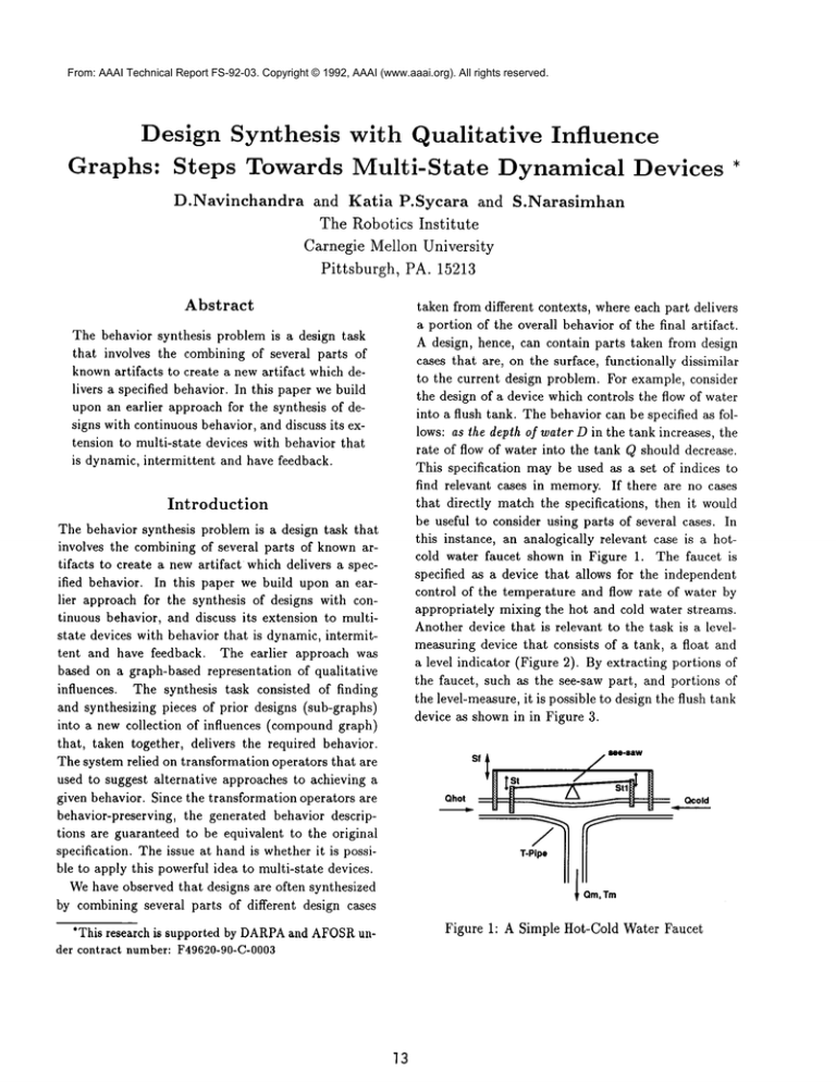
this instance, an analogically relevant case is a hotcold water faucet shown in Figure 1. The faucet is
specified as a device that allows for the independent
control of the temperature and flow rate of water by
appropriately mixing the hot and cold water streams.
Another device that is relevant to the task is a levelmeasuring device that consists of a tank, a float and
a level indicator (Figure 2). By extracting portions
the faucet, such as the see-saw part, and portions of
the level-measure, it is possible to design the flush tank
device as shownin in Figure 3.
The behavior synthesis problem is a design task
that involves the combining of several parts of
knownartifacts to create a new artifact which delivers a specified behavior. In this paper we build
upon an earlier approach for the synthesis of designs with continuous behavior, and discuss its extension to multi-state devices with behavior that
is dynamic, intermittent and have feedback.
Introduction
The behavior synthesis problem is a design task that
involves the combining of several parts of knownartifacts to create a new artifact which delivers a specified behavior. In this paper we build upon an earlier approach for the synthesis of designs with continuous behavior, and discuss its extension to multistate devices with behavior that is dynamic, intermittent and have feedback. The earlier approach was
based on a graph-based representation of qualitative
influences. The synthesis task consisted of finding
and synthesizing pieces of prior designs (sub-graphs)
into a new collection of influences (compoundgraph)
that, taken together, delivers the required behavior.
The system relied on transformation operators that are
used to suggest alternative approaches to achieving a
given behavior. Since the transformation operators are
behavior-preserving, the generated behavior descriptions are guaranteed to he equivalent to the original
specification. The issue at hand is whether it is possible to apply this powerful idea to multi-state devices.
Wehave observed that designs are often synthesized
by combining several parts of different design cases
sfl
~, m-°o~
Qcold
Qhot,
~
9
Om, Tm
Figure 1: A Simple Hot-Cold Water Faucet
*This research is supported by DARPA
and AFOSR
under contract number: F49620-90-C-0003
]3
From: AAAI Technical Report FS-92-03. Copyright © 1992, AAAI (www.aaai.org). All rights reserved.
Figure 2: Level Measuring Device
Tap
See Saw
Tank
Figure 3: A flush tank
The relevance of the faucet case to the design of
the flush tank is not easy to recognize because: (a)
the functional descriptions of the two devices are completely different, and (b) the whole faucet is not relevant to the target problem. Wehave developed a synthesis approach and a system (CADET)that performs
such synthesis through elaborations.
The primary idea underlying CADET’ssynthesis algorithm is to compose new designs by synthesizing
parts of previous designs. Each design is represented as
a directed graph of influences. An influence is a qualitative differential (partial or total) relation between
two variables one of which is dependent and the other
an independent variable. In processing influences, we
use qualitative calculus operating in the quantity space
{+, 0, -}, i.e. increasing, steady and decreasing. For
example, in a tap, the rate of flow of water is influenced by the opening of the tap. These influences are
organized as directed acyclic graphs. In general, an influence graph is a directed graph whosenodes represent
the variables of concern and whose arcs are qualitative
values depicting the influence of one variable on another. An influence graph represents the continuous,
monotonic behavior of a device. In other words, all
parameters either increase, decrease or remain steady
for the entire operation of the device.
In CADET
the specification for a new design is also
represented as an influence graph. All cases in memory
are also represented as graphs. The system’s job is to
look for previous designs that match the specification
graph. If no matching case is found, then subgraphs of
previous cases are searched for. The subgraphs are retrieved and combined to provide the complete solution.
In this way the system can find sub-parts of manycases
that together, deliver the goal behavior. If, however,
CADET
is unable to find matching cases, it elaborates
the given specifications using two transformation operators. The first transformation is serial, it converts
the influence (influences A B) to (and (influences
(influences X B)). The second transformation is parallel, it converts (influences A B) to (and (influences
X) (influences A Y) (influences Y B) (influences
The transformations introduce new, unknownvariables
X and Y. These variables are bound by matching the
elaborated behavior to cases in memory.
The idea behind using transformations, is that the
transformed specification might be found to match a
previous case. For example, suppose the goal influence is: (influences heat-flow rotational-motion). Also
assume that there are no cases that match this behavior. In other words, the system does not know of a
device that can make a heat-flow create a rotationalmotion. This is where elaboration can help. By elaboration the influence becomes: (and (influences heatflow X) (influences X rotational-motion)). The first
fluence (influences heat-flow X) might match a boiler
that converts heat-flow into steam-pressure. Once X
is bound to steam-pressure, then the second influence might match an steam-engine that coverts steampressure into rotational-motion. In this way, elaboration is able to find alternative ways of achieving a behavior. This is in contrast to other approaches that
assume a priori knowledge of the domain laws and
1models that will be part of the solution [Williams 90]
Note that the original goal would not have retrieved
the boiler and the steam-engine. Elaborations can expose hidden ways of solving a given problem. CADET
systematically applies the operations to generate complex influence graphs from simple ones (see Figure
4). The search space is controlled by using physical laws and principles to prune awayinfeasible states
1Adetailed discussion of the relation between CADET
and other approaches such as Ibis may be found in
[Navinchandra 91a, Kannapan91]
From: AAAI Technical
FS-92-03.
Copyright © 1992,
AAAI (www.aaai.org). All rights reserved.
[Navinchandra
91b]. Report
Behavioral
constraints
are also
used to control the search.
"Ix
",,=7 --
D .....
~ .......
Schematic
Figure 4: Elaboration "l~ee
Another important issue is indexing and retrieval.
While this issue is important to the success of a design
system, we will not cover indexing here. CADET’s
indexing mechanismis covered in [Sycara 91].
Weare currently extending the approach to accomplish conceptual case-based design synthesis of multistate devices. A qualitative representation for a multistate device is a graph, where each node is a continuous behavior state (expressed in terms of an influence
graph, see next section) and arcs are transitions. The
arcs are labeled by the conditions that cause the transition to occur. With respect to multi-state devices we
have two insights. First, the goal elaboration and subbehavior matching techniques we have developed can
be applied within each state to yield appropriate case
pieces. Second, the device state transitions themselves
will also be used as indices to find connections that
enforce the desired transitions.
Representing
Dynamical
(time
-(+)-->
theta
-(.)->
k.... ’" ---
h
J
Tx = Tx (mini
State Diagram
°360
(Rt
h°t
.
taati~
n
,
~
~~l~
.
Tx(max)
(Tx)Translation
,
,
~
pushing pulling
Transition
!~~
Tx(ra~.~
Diagram
Figure 5: Representations of slider-crank
mechanism
parts of the artifact. The schematic, on the other hand
only has information on the parts and the type of connection between them, geometric topology information
is dropped. At the next level, we have the Influence
State Diagram (ISD) which portrays relationships between dependent an independent parameters. It also
has information on the transition conditions. Finally,
the transition diagram is a plot of the actual behavior of the device for a given input on the independent
variables (8). It captures the temporal relationships
between design parameters. As we will see later, the
transition diagramis critical for the recognition of design bugs, and helps identify changes that can lead to
successful design adaptations..Note, that for a given
ISD there can be many different transition diagrams
that satisfy the IND.
Devices
In general, a dynamical device has many states, where
each state has continuous monotonic behavior. As
an example of a simple multi-state device consider a
slider-crank mechanism, shown in the figure 5. There
are two continuous states that this device exhibits:
pushing and pulling. Whenthe device is pushing, the
rotation of the wheel (0) positively influences the horizontal translation of the slider (Tx). This relation
expressed as follows: theta ~ Tz. In the pulling
state, the influence is negative. The transitions between states occur when the independent parameter 0
reaches certain values (180 or 360).
The figure shows four representations: the design,
the schematic, the influence state diagram (ISD) and
the transition diagram. The design is a geometric representation showingthe physical relationships between
Simulation programs such as QSIM[Kuipers 86] and
QPE[Forbus 84] can take the ISD as input and can
produce the transition
diagrams. Newer work on
qualitative dynamics can take a schematic and produce the transition diagram [Joskowiez 91]. Some of
15
From: AAAI Technical Report FS-92-03. Copyright © 1992, AAAI (www.aaai.org). All rights reserved.
these approaches can also use geometric information
in the design to envision the behavior [Joskowicz 88,
Faltings Expected in 1989]. Weare doing just the opposite! The design task is to take an input in terms of
an ISD or a transition diagram and to convert it into
a schematic of a device that will deliver the behavior
specified. CADET
currently takes a single-state
ISD
and produces a schematic automatically for any kind of
single-state device, regardless of complexity and novelty.
Characterizing
A trigger is a causal relationship that is introduced
between two transitions.In a multi state device, there
are 9 transitions,
shown in the Figure 6.Transitions
don’t occur by themselves. They have to be triggered.
There are three types of events that can cause a trigger: (1) an outside signal could independently start
some process (e.g. turning on a switch), (2) a parameter reaches some pre-determined value, and (3) one
parameter transitions causing something else to transition. Whenevera transition occurs the system moves
from one state to another: it is here that the design
system has to find ways of makingthe transitions trigger at the right time. For example, if we want a design that makes a "peak" transition to trigger a "step"
transition (see figure above), we are asking for a switching mechanismthat makes its step transition only at a
given threshold level of a continuously increasing input
signal. There is a need for a way of recognizing and
indexing methods of trigger and transition in devices.
Transitions
In each continuous state, a parameter can be either
increasing, decreasing or remain steady. A transition
is a change from one continuous state to another. In
devices, the transition of one parameter could influence the transition of another. This is called a trigger.
For example, while opening a tap, the flow of water
increases with the amount of tap opening. Whenthe
tap is fully open, the flow rate stops increasing. In
terms of transitions and triggers: when the opening
process transitions from increasing to steady, the flow
rate also transitions from increasing to steady. A parameter triggers the transition of another via an influence. So, an influence represents the causality behind
INC
STD
\
\
/--
DEC
A-
INC
STO
\\
V
J
step
DEC
:V
, valley
Figure 6: Trigger types
any transition. A variable X can trigger a transition in
Z, either when X itself transitions or X reaches some
determined value. For example, a billiard ball rolling
down the table towards a pocket has an increasing X
(horizontal position) but the Z remains steady. When
the ball reaches the pocket (X = Xpocket) then Z transitions from steady to increasing. So X = Xpocket
ltriggers Z to transition. Weknowhow to design devices within a state, we don’t knowhow to design for
triggers and transitions. Hence, we will concentrate on
characterizing the transitions.
At this stage, we have identified the existence of 81
types of triggers. Weare proceeding with identifying mechanismsthat actually produce these behaviors.
This kind of characterization has not been done before.
The table above is a largely uncharted space.
Elaboration with Triggers and
Transitions
Our preliminary characterization of transitions has
led to the identification of 81 different types of triggers.
Can elaboration methods be applied to transitions?
This is the main question facing us today. Let’s look
]5
From: AAAI Technical Report FS-92-03. Copyright © 1992, AAAI (www.aaai.org). All rights reserved.
at an idea that might work.
Consider the situation where you have to make a
valley transition trigger a step transition. In other
words, some parameter (X) which is decreasing and
suddenly changes to increasing should trigger another
parameter (Y) which is steady to step to new level
and continue to be steady. The specification: (trigger valley(X) step(Y)) can now be used as in
to find matching cases or pieces of cases. If we cannot find a case, the trigger can be elaborated to: (and
(trigger valley(X) transition(Z)) (trigger transition(Z)
step(Y))). In other words, two triggers occur, through
an unknowntrigger on an unknownparameter Z. Let’s
examine this idea in detail through an extended example.
d
=
D~
"’>
Dmin
Filling
Figure 8: ISD For Goal Specification
form of the multiple states that a device can take. A
qualitative state representation of the same specification is shownin Figure 8.
Elaboration
based Retrieval
From the timeline of the specification (Figure 7),
can see that the flow Q2 should be zero when the tank
is filling, it should then increase to a point and stay
there till the draining is over. In other words, Q2
should stay triggered even after the triggering condition (height of water) starts receding. The required
transition is shownin the figure below. Wewant to go
from a peak to a step. The peak is the depth of water,
and the step is the flow rate Q2. From the table of
81-triggers, we can find devices that fill the gaps. The
goal is: (trigger peak(depth-of-water) step(flow-rate)).
Example: Design of an Automatic
Flushing Tank
Consider the following design task. Given a tank with
water flowing into it. The tank has a pipe (opening)
at the bottom, from where the water drains out.
01
\
I
i
i
,
i
,
i
,
Tfansilion
Rowrate
(m)
Figure 7: Automatic Flushing Tank Specification
Let’s assume we are unable to find any case that
satisfies the above trigger condition. One can look for
devices that provide the trigger for different quantities. An elaboration that can be made is: (and (trigger peak(depth-of-water)
peak(X)) (trigger peak(X)
step(Y)) (trigger step(Y) step(flow-rate))).
two unknownvariables introduced. The middle trigger
will match a rocker switch (shown below). This device
gives a peak to step trigger between a horizontal translation (Tx) and a rotation (theta). This device gives
the (trigger peak(Tx) step(theta)). So we have
to step trigger, but the variables don’t match the original index. The next step is to make a trigger connection between trigger peak(depth-of-water) peak(Tx))
Wewant to design a device that will automatically
fill and drain the tank. Wewant the tank to fill up to a
pre-determined level, and then drain out. After draining, the tank should start filling up again. The desired
behavior specification is shown below. The depth of
water is shown on a time line. Whenthe water is below the level D*, the outflow (Q2) is zero. Once the
water reaches the desired level, draining starts. The
outflow jumps from zero up to a finite positive level.
Assumethat we are also given that the flow rate Q2 is
larger than the constant inflow rate of Q1. This will
ensure draining, when Q2 is non-zero.
The time line-representation is a visually oriented
17
From: AAAI Technical Report FS-92-03. Copyright © 1992, AAAI (www.aaai.org). All rights reserved.
and to go from (trigger step(theta) step(flow-rate)).For
the index (trigger peak (depth-of-water) peak(Tx)),
let’s assume that we use a float on the water. This
produces the relation between depth-of-water and a
vertical translation Ty. The vertical translation has to
be then converted into a horizontal translation Tx that
can push the switch. So, our new subgoal is (trigger
peak(Ty) peak(Tx)). This behavior can be provided
by a rocker switch combined with a crank mechanism.
The final design is shown in Figure . As the depth
of water increases beyond D., the float begins to rise.
This tilts the see-saw, and pushes out the crank. The
crank pushes the rocker switch. The rocker rotates for
a while and then clicks. This opens the water. As
the water level drops, the float also drops. This pulls
back the crank. As the crank comes back, it starts
pushing the rocker back. At the critical point, the
rocker makes a step transition and suddenly closes the
outflow. The transition between water depth and flow
rate is as specified.
that integrates case-based synthesis and qualitative
reasoning. The approach is based on domain independent techniques for elaborating a design goal specification. Based on this elaboration, desired sub-behaviors
are recognized, retrieved from a design case-base and
synthesized. The approach has been extensively tested
in the conceptual design of continuous and reciprocating devices. Weare currently extending the approach
for multi-state devices. Our intuition is that the key
to such an extension lies in explicitly representing and
characterizing triggering conditions for state transitions.
References
B. Faltings. "Qualitative kinematics in mechanisms."
Artificial Intelligence, Expected in 1989.
K. Forbus. "Qualitative process theory." Artificial
Intelligence, 24:85-168, 1984.
L. Joskowicz and S. Addanki. "From kinematics to
shape: An approach to innovative design." In Proceedings of the seventh National Conference on Artificial Intelligence (AAAI88), pages 347-352, 1988.
L. Joskowicz and E. P. Sacks. "Computational kinematics." Artificial Intelligence, 51, 1991.
S. M. Kannapan and K. M. Marshek. "Engineering
design methodologies: A new perspective." In Intelligent Design And Manufacturing, NewYork, WileyEastern, 1991.
B. Kuipers. "Qualitative simulation." Aritifial Intelligence, 29:289-338, 1986.
Rowr~e
Notice that the complexity in the design is being
introduced, not by the parts retrieved for continuous
behavior, but by the parts that handle and properly
trigger transitions between the various states of the
device. In our example, the continuous state only requires a valve, a float, and a connection between them.
All the other parts that have been introduced are required for transitions.
Conclusion
The focus of our research is the conceptual design of
dynamical systems. We have developed an approach
D. Navinchandra, S. Narasimhan, and K. P. Sycara.
"Qualitative reasoning methods in design." In Intelligent Design And Manufacturing, NewYork, WileyEastern, 1991.
D. Navinchandra, K. Sycara, and S. Narasimhan. "A
transformational approach to case based synthesis."
AI EDAM,5(1), 1991.
K. Sycara and D. Navinchandra. "Index transformation techniques for facilitating creative use of multiple cases." In Proceedings of the twelfth International
Joint Conference on Artificial Intelligence, 1991.
B. Williams. "Interaction-based invention: Designing
novel devices from first principles." In Proceedings of
AAA1-90, pages 349-356. Boston, MA, 1990.


