From: AAAI Technical Report FS-92-01. Copyright © 1992, AAAI (www.aaai.org). All rights reserved.
Toward
a Comprehensive
Knowledge-Base
Engineering
for
Duvvuru Sriram
Intelligent Engineering Systems Laboratory
Department of Civil Engineering
1-253, MIT, Cambridge, MA02139
sriram@athena.mit.edu
Abstract
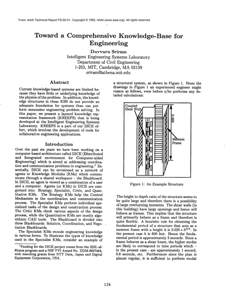
a structural system, as shown in Figure 1. From the
drawings in Figure 1 an experienced engineer might
reason as follows, even before s/he performs any detailed calculations:
Current knowledge-based systems are limited because they have little or underlying knowledgeof
the physics of the problem. In addition, the knowledge structures in these KBSdo not provide an
adequate foundation for systems than can perform innovative engineering problem solving. In
this paper, we present a layered knowledge representation
framework (KREEPS)that is being
developed at the Intelligent Engineering Systems
Laboratory. KREEPSis a part of our DICE effort, which involves the development of tools for
collaborative engineering applications.
Coupled
Shear ~zllq
!!
II 1
I
’ D
Introduction
I!
II
il
II
II
el
liII
Ill
Ill
IBi
Over the past six years we have been working on a
computer-based architecture called DICE(Distributed
and Integrated
environment for Computer-aided
Engineering) which is aimed at addressing coordination and communication problems in engineering. 1 Essentially,
DICE can be envisioned as a network of
agents or Knowledge Modules (KMs) which communicate through a shared workspace - the Blackboard.
In DICE,an agent is viewed as a combination of a user
and a computer. Agents (or KMs) in DICE are categorized into: Strategy, Specialist, Critic, and Quantitative
KMs. The Strategy KMshelp the Control
Mechanism in the coordination and communication
process. The Specialist KMsperform individual specialized tasks of the design and construction process.
The Critic KMscheck various aspects of the design
process, while the Quantitative KMsare mostly algorithmic CADtools. The Blackboard is divided into
three Blackboards: Solution, Coordination, and Negotiation Blackboards.
The Specialist KMsencode engineering knowledge
in various forms. To illustrate the types of knowledge
used in the Specialist KMs, consider an example of
M~ment
Frame
Ill
III
Ill
Ill
Figure 1: An Example Structure
1Fundingfor the DICEproject comesfrom the IESLaffiliates program and a NSFPYI AwardNo. DDM-8957464,
with matching grants from NTTData, Japan and Digital
Equipment Corporation, USA.
126
The height to depth ratio of the structure seems to
be quite large and therefore there is a possibility
of large overturning moments. The shear walls (in
this building) have large openings and hence will
behave as frames. This implies that the structure
will primarily behave as a frame and therefore is
quite flexible. A heuristic rule for obtaining the
fundamental period of a structure that acts as a
momentframe with a height h is 0.025 ¯ h3/4. In
the present case h is 600 feet. Hence the fundamental period is approximately 3 seconds. Since a
frame behaves as a shear beam, the higher modes
are likely to correspond to time periods which in the present case - are approximately 1 second,
0.6 seconds, etc. Furthermore since the plan is
almost regular, it is sufficient to perform modal
From: AAAI Technical Report FS-92-01. Copyright © 1992, AAAI (www.aaai.org). All rights reserved.
analysis and consider modes of vibration corresponding to 3, 1 and 0.6 seconds to estimate forces
and deflections. The overturning momentis likely
to be higher than usual since the lateral distribution will be nonlinear instead of being almost
linear. The slight non-symmetry in the plan will
cause somelateral forces which in turn will cause
torsion. Since the shear walls have large openings, there is a possibility of serious degradation
of performance due to the torsion. The columns
in the first story are very tall and this wouldcause
very large drift in the first floor which might cause
non-structural damage. The coupled shear walls
are not identical in nature, i.e., they possess different stiffnesses. This can cause large forces in the
links and since the links are not restrained laterally, there is a serious possibility of their buckling
...
The above type of analysis usually occurs during the
preliminary design/analysis stage. In the detailed design/analysis stage, the engineer may develop an appropriate numerical model (such as a finite element
model), perform the analysis and then interpret the
results. All these tasks are knowledge intensive and
require considerable engineering judgment.
The above example suggests the following types of
knowledge structures and reasoning mechanisms that
engineers utilize:
1. Objects, such as frame, building.
2. Properties that describe the objects, such as height
of the building.
3. Causality that describes causal relationships between various entities (objects or events), such
non-symmetrycauses lateral-forces causes torsion.
4. Activities, which consume resources and time, such
as the construction of the building.
5. Heuristic knowledge, such as:
If the building behaves as a moment frame
then the fundamental period of the structure is
0.025 ¯ h3/4, where h is the height of the structure.
6. Qualitative analysis, such as:
The slight non-symmetryin the plan will cause
somelateral forces which in turn will cause torsion.
7. Modeling, such as the mapping from the physical
world to an engineering model;
8. Analogical reasoning, such as:
Since a frame behaves as a shear beam the
higher modes are likely to correspond to time
periods which are approximately 1 second, 0.6
second, etc.
Here an analogy is made between the frame and the
shear beam. Since the higher modes of a shear beam
are likely to correspond to time periods which are
approximately 1 second, 0.6 seconds, etc., the modes
of the frame will have similar characteristics.
9. Uncertain reasoning, such as the large drift might
cause non-structural damage.
10. Behavior of Systems, such as the behavior of the
shear beam.
11. Function, such as the function of a shear wall is to
resist lateral loads.
12. Spatial Reasoning, such as the reasoning involved in
determining that there is non-symmetryin the plan.
13. Approximate Quantitative Analysis (back of the envelope calculations), such as:
Calculating stiffness distribution, estimating
lateral load distribution etc.
14. Interpretation, such as the interpretation of data
from a complex computer analysis.
In addition to the above, engineers deal with time, procedures, design plans, constraints, etc..
In order to effectively address problems such as the
one posed above, we need to develop a comprehensive
knowledge-base (CKB)of engineering knowledge structures. In the next section, we describe a framework
that we have been developing for engineering problem
solving.
KREEPS: Knowledge
Representation
Environment
for Engineering
Problem
Solving
KREEPSis being implemented as a layered architecture, as shown in Figure 2. The various layers are
briefly discussed below.
1. OODBMS.
The lowest layer is an object-oriented
database management system (OODBMS). Currently we are using EXODUS,
which is a C++-based
system developed at University of Wisconsin, Madison. The OODBMS
is being populated with engineering entities, such as beams, columns, gears,
etc, relevant to the civil/mechanical engineering domains.
2. COSMOS. COSMOS(C++ Object-oriented
System Made fOr expert System development) supports the development of knowledge-based systems. It provides the following extensions to C++:
1) dynamic schema manipulation; 2) a modified
RETEnetwork-based forward chaining strategy; 3)
a bayesian-based backward chaining strategy; 3)
composite objects; 4) user interfaces for encoding
engineering knowledge; etc.
3. COPLAN. COPLAN(COnstraint
PLANner) is
constraint managementsystem, which uses AI-based
planning techniques for solving the constraint satisfaction problem (CSP). A planner is used as a toplevel control process, guiding the search for a solution and producing an appropriate solution plan
127
From: AAAI Technical Report FS-92-01. Copyright © 1992, AAAI (www.aaai.org). All rights reserved.
TM.
when the problem is solvable. The CSPis described
in Motif/X-windows
by a goal. Usually the goal states which constraints
should be satisfied but is moregenerally a list of assertions that should be true in the final world. The
planner produces a non-linear plan at an abstract
level where the different steps needed to achieve the
goal are partially ordered. At the bottom level, numerical and symbolic methods are chosen in the order defined by the plan. The execution of a plan
consists in executing the above procedure. This is
very efficient in the case where one wants to vary
a parameter over a certain range and to study its
influence on other values for a given CSP.
4. QRS. QRSis a qualitative reasoner. Weare yet to
develop this layer.
5. GNOMES.One of the basic issues in developing
collaborative engineering systems is the representation of the product information which supports sharing. This product information includes not only the
geometric data of the physical parts of the product
and their relationships but also non-geometric information such as details on functionalities of the
parts, constraints, and design intent. Weare developing an information model - called SHARED
which supports: multiple levels of abstraction and
different functional views; multiple levels of geometric representation; and constraint managementfacilities (COPLAN)for enforcing integrity between
various views. The geometric manipulations are performed by GNOMES,
which is a non-manifold geometrical modeler. It utilizes the selective geometry
complex data structure developed by Rossignac at
IBM. GNOMES
has been implemented in C++.
6. Task Specific
Problem Solvers. The kinds of
problems that are encountered in engineering can
be laid out along a derivation-formation spectrum.
In derivation problems, the problem conditions are
posed as parts of a solution description; the possible outcomes exist in the knowledge-base. Essentially, the solution to these problems involves the
identification of the solution path. In formation (or
synthesis) problems, problem conditions are given
in the form of properties that a solution must satisfy as a whole. Several domain independent problem solvers addressing various tasks will exist at this
level. CONGEN
addresses problems at the formation end. It is implemented in C++ and provides
extensive support for design problem solving.
7. CBR. At this level we will be supporting a casebased reasoner. Anarchitecture for a case-based reasoner has been developed. It is being implemented
over COSMOS.
8. Knowledge Editing Tools. Adequate user interfaces are provided for encoding various knowledge
structures are being developed.
The entire KREEPSframework is being implemented
TM workstation, with the user interfaces
on an UNIX
KNOWLEDGEEDITING TOOLS
Figure 2: Layered Architecture
for KREEPS
Acknowledgments
; The DICEproject is headed by D. Sriram and Robert
Logcher. Other researchers involved in various aspects of KREEPSare: Albert Wong (GNOMES,COSMOS, SHARED,User Interfaces),
S. Gorti (CONGEN, COSMOS), Bruno Fromont (COPLAN, COSMOS), Fred Garcia (COPLAN), V. Murali (OODBMS,
User Interfaces), Ashok Gupta (Object Modeling),
niosky Pefia (Design Rationale Representation, CBR),
V. Vaidyanathan (COSMOS).
128

