Field Demonstration of Surface Human-Robotic Exploration Activity
Liam Pedersen1, William J. Clancey2,3, Maarten Sierhuis4, Nicola Muscettola2, David E. Smith2,
David Lees1, Kanna Rajan2, Sailesh Ramakrishnan5, Paul Tompkins5, Alonso Vera2, Tom Dayton5
1
Carnegie Mellon University; Inc; NASA Ames Research Center
2
NASA Ames Research Center, Moffett Field, CA
3
Institute for Human & Machine Cognition, Pensacola, FL
4
RIACS; NASA Ames Research Center
5
QSS Group, Inc; NASA Ames Research Center
NASA Ames Research Center, MS 269-3, Moffett Field, CA 94035-1000
{pedersen, msierhuis, mus, lees, sailesh, pauldt, de2smith, kanna, tdayton}@email.arc.nasa.gov
{william.j.clancey, alonso.vera}@nasa.gov
Abstract
We demonstrated integrated technology for multiple crew
and robots to work together in a planetary surface
exploration scenario.
Highlights include dynamic
replanning, “many to many” rover commanding, efficient
human-system interaction and workflows, single cycle
instrument placement, and data management.
sequences, to direct teleoperation—to cope with the full
spectrum of situations expected.
Introduction
To support the Vision for Space Exploration, NASA’s
Collaborative Decision Systems (CDS) 2005 program
sought to:
Develop and demonstrate information technology for
self-reliant operation and multi-agent teaming, enabling
human and robotic individuals and teams to operate
exploration missions in harsh dynamic environments in
a sustainable, safe, and affordable manner.
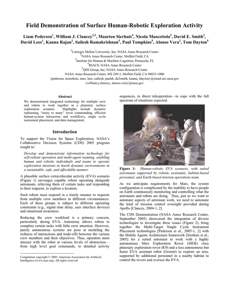
A plausible surface extravehicular activity (EVA) scenario
(Figure 1) envisages capable robots operating alongside
astronauts, relieving them of certain tasks and responding
to their requests, to explore a location.
Such robots must respond in a timely manner to requests
from multiple crew members in different circumstances.
Each of these groups is subject to different operating
constraints (e.g., signal time delay, user interface devices)
and situational awareness.
Reducing the crew workload is a primary concern,
particularly during EVA. Autonomy allows robots to
complete certain tasks with little crew attention. However,
purely autonomous systems are poor at modeling the
richness of interactions and trade-offs between the various
crew members and their objectives. Thus, operators must
interact with the robot at various levels of abstraction—
from high level goal commands, to detailed activity
Compilation copyright © 2005, American Association for Artificial
Intelligence (www.aaai.org). All rights reserved.
Figure 1: Human-robotic EVA scenario, with suited
astronauts supported by robotic assistants, habitat-based
personnel, and Earth-based mission operations team.
As we anticipate requirements for Mars, the system
configuration is complicated by the inability to have people
on Earth continuously monitoring and controlling what the
astronauts and robots are doing. Thus, just as we want to
automate aspects of astronaut work, we need to automate
the kind of mission control oversight provided during
Apollo [Clancey, 2004-1, 2].
The CDS Demonstration (NASA Ames Research Center,
September 2005) showcased the integration of diverse
technologies to investigate these issues (Figure 2), bring
together the Multi-Target Single Cycle Instrument
Placement technologies [Pedersen et al., 2005-1, 2] with
the Mobile Agents Architecture framework [Sierhuis et al.,
2005] for a suited astronaut to work with a highly
autonomous Mars Exploration Rover (MER) class
planetary exploration rover (K9) and a less autonomous but
faster EVA assistant robot (Gromit) to explore an area,
supported by additional personnel in a nearby habitat to
control the rovers and oversee the EVA.
Figure 2: NASA ARC Human-robotic demonstration scenario, with single astronaut commanding two distinct rovers (K9, a
highly autonomous MER class rover, and Gromit, a rapid robotic assistant) supported by habitat-based personnel.
Numerous factors drove the design of the simplified
system we configured for our demonstration. The plannerrobot-agent system must accept requests from multiple
crew members and provide a mechanism for resolving
conflicts between them. A single robot operator (by
assumption, a crew member who remains inside the
habitat) must be able to oversee the system and provide
input where necessary, but should be involved in the EVA
only when a request directed at a robot cannot be handled
autonomously. Space-suited crew members must be able
to verbally issue and confirm high-level goal requests. All
crew member activities and robot requests must be
coordinated in a natural and timely manner. Finally, the
system must adapt to faults and off-nominal resource (time
and energy) consumptions.
We introduce a framework for a system that allows the
multiple crew members, both in a habitat and on EVA, to
carry out tasks by working together with multiple robots
under the control of a single centralized planner program
and overseen by a single operator. The system is designed
for tasks that can be decomposed into loosely coupled subtasks that each person and robot can execute. By using a
distributed multiagent architecture, people, robots, tools,
and instruments, interfaces can be integrated into a
coherent data and workflow system.
The subsequent sections describe the CDS Demonstration
mission scenario, the resulting research issues we have
chosen to investigate, an outline of the system architecture,
and some of the key technologies.
images of an area as part of a pre-EVA survey. Astronauts
exit the habitat to commence an EVA, overseen by a inside
crewmember (“habcom”), also responsible for controlling
the rovers.
As the astronauts do their EVA, an automated system
monitors progress, reminding them of their next activities,
alerting habcom if anything unusual happens.
At a particular location, an astronaut discovers a rock
worthy of further investigation. After recording a voice
note and taking pictures, the astronaut verbally requests
assistance from the Gromit robot, interrupting its activities
and commanding it to go to the astronaut to take a picture
of the astronaut pointing at the rock. The astronaut asks
the K9 robot to get a microscopic image of the rock prior
to the scheduled end of the EVA. Whilst the astronaut
resumes other activities, K9’s mission planner software
determines if the request of K9 can be accommodated
without compromising earlier requests, and if not, it asks
the rover operator (habcom) for approval.
The request is passed on to K9, which gets the requested
microscopic image, incorporating it into a geographic
information system accessible to the crew and the remote
science team, who have sufficient time to peruse it prior to
EVA end, and to request that the astronaut take a sample of
the rock on her way back to the hab.
The actual demonstration was slightly simplified, with one
astronaut, distinct rover operators and habcom, and
involvement of the rover operator every time new goals
were requested of K9.
Mission Scenario
The CDS demonstration mission scenario begins with two
rovers, K9 and Gromit, at work. K9 is a highly
autonomous MER class exploration rover, tasked with
going to multiple rock targets and acquiring close up
microscopic images of each. Gromit meanwhile is getting
Research Issues
Research issues in this project include dynamic re-planning
and repairing of plans in response to new task requests or
faults, efficient human-systems interaction and workflows,
and visual target tracking for sensor placement on objects
subject to extended occlusions. (Note that EVA issues
relating to interaction between astronauts, such as
preventing robots or agents from unnecessarily interrupting
human activities, are eliminated in this demonstration by
having only one astronaut.)
Flexible Robot Command Cycles
The rovers need to amend their activity plans at any time in
response to new task requests from the crew, insufficient
resources, or activity failures. The goal is the continuous
adjustment of a long term rover operations plan (possibly
spanning days, weeks or months) as new circumstances
and goal requests materialize.
This is in stark contrast to the current spacecraft, which
start each command cycle with a completely fresh activity
plan that is deliberately conservative to avoid resource
limitations, and contains only limited recovery options if
the rover is unable to complete an activity.
Overcoming these limitations requires re-planning on the
fly, incorporating the robot’s current execution state with
the new and remaining goals.
Also, the system must tolerate signal delays, as new goal
requests or other information can come from mission
control on Earth as well as from onsite crew.
"Many to Many" Robot Commanding
Task requests can come from many sources (EVA
astronauts, intravehicular activity—IVA—astronauts,
ground based operators) and must be dispatched to the
appropriate robot, taking into account both the robot
capabilities and the user interface (UI) at the task
requestor’s disposal (for example, a suited astronaut can
use speech but not a sophisticated graphical user
interface—GUI).
Ultimately, a single rover operator should be responsible
for all robots, even though task requests may come from
other crew members. Autonomy and careful workflow
design are needed for this person to oversee many robots
concurrently, the goal being that operator attention will be
required only to handle complex or off nominal situations,
and to resolve task conflicts not adequately modeled by
robot plans.
Real Time EVA Crew Monitoring and Advising
From studying the transcripts and videos of the Apollo
EVAs, we draw two important lessons. Firstly, the
astronauts on the Moon, though sometimes working as a
team, primarily had independent work assignments strictly
planned and trained for, before the mission. The capsule
communicator (CapCom1) coordinates the work, serving as
a virtual team-member and assistant to the astronauts. For
1
The name derives from early space flight, when Mercury was called a
capsule rather than a spacecraft.
example, instead of asking each other, the astronauts asked
CapCom where they could find their tools on the lunar
rover. It is the CapCom who acted as their personal
navigator [Clancey et al., in preparation].
Secondly, the CapCom is responsible for continuously
monitoring EVA progress, time spent at worksites,
activities to be done by the astronauts; and coordinating the
discussions between crew and mission control.
Crewed missions with long latency communications links
to Earth will require automation of CapCom tasks. In this
situation the role of CapCom will fall to a crewmember
(“HabCom”) in the habitat. Because crew time is valuable,
it is imperative to automate some of the mundane CapCom
tasks, such as monitoring the astronaut locations and
duration of EVA activities, with alerts to indicate threshold
violations, advising about the EVA plan, multiple astronaut
tasks, and astronaut health.
Autonomous Instrument and Tool Placement
Because of bandwidth and power limitations, signal
latency, strict flight rules, and other factors, the MER
vehicles currently on Mars require up to three full sol
command cycles to approach a distant target and accurately
place an instrument against it. One cycle is required to
drive the rover to the vicinity of the target, another for a
correction maneuver to bring the target within reach, and a
final uplink to command the placement of the rover
manipulator on the target feature itself.
Our goal is to autonomously approach and place an
instrument on multiple features of scientific interest up to
10 m distant with 1 cm precision in a single command
sequence uplink.
This is inspired by early design
requirements for the 2009 Mars Science Laboratory rover,
but goes beyond it in the pursuit of multiple targets per
command cycle.
Achieving these goals requires broad advances in robotics,
autonomy, and human-system interaction methods:
• Precision navigation to multiple points in the worksite,
whilst avoiding obstacles and keeping targets in view.
This requires visual target tracking. Note that GPS
technology is not precise enough for this task.
• Automated instrument placement, using the rover arm to
safely put the requested sensor onto the target.
• Mission and path planning, taking into account the
constraints imposed by target acquisition and tracking,
rover resources, and likely failure points.
• Immersive photo-realistic virtual reality interface for
goal specification, plan analysis, and data product
review.
The details of single cycle multi-target autonomous
instrument placement are described in [Pedersen, 2005-1,
2] and are not described further here.
Voice-Commanded Device Control
Astronauts need to control many devices while on an EVA,
such as cameras, tools, and robots. Controlling these
devices via complex GUIs while wearing spacesuit gloves
is physically and mentally difficult. Controlling such
devices with voice commands through an agent-based
intermediary provides an intention-based interface, which
helps coordinate data, instruments, and human activities.
Data Management and Display
Astronauts and rovers will acquire significant amounts of
data that must be routed, stored, and catalogued
automatically in real time. Experience with past NASA
missions suggests that finding and accessing work process,
science, and other telemetry data throughout a mission
often is not easy. Even on Earth, post hoc interpretation of
field notes is difficult. In a space suit, taking notes is
doubly difficult.
Astronauts need to dynamically name locations, and
associate them with data products (including recorded
voice notes) and samples collected at those locations.
Additional rover data products also need to be properly
catalogued, both so that the remote science team can
reconstruct what was discovered in an EVA, and for the
rover operator to instruct the rovers to go to specific named
features at any location.
Finally, data products need to be displayed in context with
overhead imagery, 3D terrain models, rover telemetry, and
execution state and mission plans, so human explorers can
rapidly identify, specify, and prioritize the many potential
targets; evaluate the plan of action; and understand the data
returned from the multiple sites that the rover visited.
System Architecture
As Figure 3 shows, each crew member is provided a
Personal Agent that relays task requests (e.g., “Inspect rock
named Broccoli when able”) to the Rover Agents, which
insert them into the Rover Data Repository, monitored by a
centralized, off-board Rover Plan Manager. The plan
manager coordinates with the rover executive to stop the
rover, upload the current execution state, and create
activity plans to achieve the new and previous goals.
For new plans to be created without requiring Rover
Operator intervention each time, the new plan could be
compared with the previous one; the Rover Operator would
be interrupted only if plan approval criteria are not met, in
which case the operator would manually edit and approve
the new plan. If necessary, the operator confers with other
crew members to establish the un-modeled priorities and
constraints. Currently this is not implemented, both
because of the complexity of the plan approval process,
and the need for the rover operator to manually designate
targets for the K9 rover to investigate.
Figure 3: CDS Demonstration system architecture.
In principle, the off-board planner could control multiple
robots. The alternative is the astronaut commanding the
rover via a rover agent, allowing the astronaut to issue
simple voice commands (“Go to location 2”) that do not
require sophisticated planning for of the rover’s actions.
The robotics and autonomy for K9 to navigate to targets
and place instruments on them is detailed in [Pedersen,
2005-1, 2]. The following sections detail the agent
architecture for routing of astronaut commands, data
products and EVA monitoring; the mission planning and
plan management system, and rover execution system, and
the rover interfaces.
Mobile Agents Architecture
Figure 4 shows the CDS configuration of the Mobile Agent
Architecture (MAA) [Clancey et al., 2004]. Each personal
or rover agent is a Brahms [Clancey et al., 1998; Sierhuis,
2001; Clancey 2002] virtual machine (an agent execution
environment) with a set of communicating agents, a set of
assistant agents (Network, Plan, Science Data, etc.), and a
set of communication agents to communicate with external
systems (Dialog, Network, Email, Science Data Manager,
etc). The entire architecture is connected via a wireless
network with an agent location manager and the necessary
agent services [Sierhuis et al., 2005].
created to the appropriate people, with hyperlink pointers
to the stored data products.
Model-Based, Planner-Driven Execution
The Intelligent Distributed Execution Architecture (IDEA)
[Muscettola et al., 2002] is a real-time architecture that
exploits artificial intelligence planning as the core
reasoning engine for interacting autonomous agents. IDEA
is used as the basis execution architecture for the K9 Plan
Manager agent, and the K9 and Gromit rover executives,
all described below.
Figure 4: Mobile Agents configuration for CDS.
Voice commanding of devices (e.g., cameras, robots,
scientific instruments), software systems, and agents is
accomplished in Mobile Agents using an open microphone,
speaker-independent approach [Dowding et al., 2006].
Every utterance is matched against more than 100 patterns
using a category-based grammar that recognizes astronautdefined names, time and distance units, and alternative
wordings. A combination of methods for coordinating
human-system interaction has been developed empirically,
including contextual interpretation, explicit confirmation,
and status tones.
Figure 6: Architecture of an IDEA agent.
Figure 5: Automatic Agent Data Management using
Semantic Web Database [Keller et al., 2004].
Another important role of the Mobile Agents Architecture
is to provide data flow and management capability for all
aspects of the mission. The current version of the
architecture includes agent interfaces to groupware tools
for distributed human collaborative mission planning and
data analysis; a semantic web database (Figure 5); data
management agents to collect, correlate, store, and forward
data; and email clients to forward mission data as they are
At the heart of each IDEA agent is a declarative model
describing the system under control of the agent, and the
interactions with other agents. The model defines discrete
parameterized states, representing persistent control modes
or states of being, and the temporal and parameter
constraints between them. States are represented as
consecutive, finite-duration tokens on one or more
timelines. Once activated, tokens command or collect data
from hardware under the control of an agent, command
other agents, or return status and telemetry data to other
agents. IDEA maintains these tokens and timelines in a
EUROPA temporal and constraint network database
Jónsson et al., 2000 managed by the Plan Server (Figure
6). Internal and external events, such as the start and end of
tokens as well as status and telemetry, are communicated
via message passing through the Agent Relay. Models can
define constraints that are contingent on the timing of
messages and the assignment of message parameters,
enabling a rich description of subsystem interactions
during execution.
operator approves the plan, the Plan Manager sends it on to
the executive, and monitors plan execution.
IDEA agents utilize one or more EUROPA-based planners
that perform constraint-based reasoning, over various
planning horizons, on the temporal database. At minimum,
IDEA agents call on a reactive planner that has a planning
horizon of the minimum time quantization for the
application. In reaction to message events and the current
state of the database, the reactive planner propagates
constraints to determine whether tokens must be activated
or terminated and to further restrict the sets of possible
token parameter values. Other application-specific
planners, represented as IDEA reactor components, can
reason deliberatively over longer planning horizons, for
example to elaborate coarsely-defined plans.
The Plan Manager is implemented as an IDEA agent. Its
declarative model governs the invocation and execution of
its various components. The IDEA reactive planner,
operating at a planning horizon of one second, propagates
model constraints and determines which component is to
be run next, given the current state of the K9 Executive,
Plan Manager, and operator interface (RSI). For example,
unless additional changes have been made to the goals,
planning is run after path generation because there is a
constraint indicating that a planning activity will follow a
path generation activity in these circumstances. The
activity planner, path generator and state estimator
components are implemented as IDEA reactor modules
whose activity is associated with the activation of specific
tokens. Implementing the Plan Manager as an IDEA agent
has allowed us considerable flexibility to explore different
control flows, and to update the system as new capabilities
and modules are developed.
Planning and Plan Management
The planning process for K9 must be capable of handling
new or changed task requests, and uncertainty or failures in
execution. As a result, the system must continually monitor
input from the operator, monitor the state of K9’s
execution, communicate state and plan information among
the components, and initiate replanning when necessary.
This overall process is the job of the Plan Manager.
The Plan Manager has several components (Figure 7), the
principle ones being the state estimator, the path planner
(PathGen), and the activity planner itself.
PlanManager
Plan
IDEA Agent
Planner Reactor
Control messages
CDSPlanner
ExecRelay
Telemetry messages
PathGen Reactor
PathGen
Exec
Observer
State Estimator Reactor
Update RSI
Suspend
The planning engine used in the plan manager is a
constraint-based planner [Frank & Jónsson, 2003] built on
top of the EUROPA constraint management system
[Jónsson et al., 2000]. Often, it is impossible to achieve all
of the goals provided to the planner, given the time and
energy available to the rover; the planning problem is an
oversubscription problem [Smith, 2004]. To determine
which subset of the goals to achieve, and in which order,
the planner solves an abstract version of the problem in the
form of an orienteering problem, a variant of the traveling
salesman problem. A graph is constructed and labeled
using the path network, current rover location, goal
locations and values, and expected energy and time
required for traversing the different paths. A solution of
the resulting orienteering problem gives the optimal subset
and ordering of the goals. This information is used by the
planner to construct the detailed action plan. Details of
this technique can be found in [Smith, 2004].
Rover Execution
PlanManagerInterface
Process Goals
Approve Plan
Suspend
Figure 7: Architecture of the Plan Manager.
If the rover operator (a human) signals that there are new
or changed task requests (goals), the Plan Manager sends a
command to the executive, suspending execution by the
rover. Once execution is suspended, the Plan Manager
determines the current state, based on the most recent rover
telemetry. Using this state information and the goals
provided by the rover operator, PathGen finds a network of
possible routes between the current location and the
locations of interest. This path network, along with the
state and goal information, is then provided to the planner,
which generates a revised plan. The path network and plan
are then sent back to the rover operator for approval. If the
Like the K9 Plan Manager, the executives on both the K9
and Gromit rovers are also implemented as IDEA agents.
To ensure consistency of planning and execution and to
minimize model repetition, the K9 Executive and Plan
Manager share a large portion of the models related to K9
operation and Plan Manager-Executive interactions. The
K9 Executive loads plans from the K9 Plan Manager using
a deliberative planner called the Goal Loader (Figure 6) to
trivially reconstruct the plan in the executive database.
Once the plan is loaded, the executive uses its reactive
planner, operating on a one second planning horizon, to
determine which tokens must be activated or terminated at
the current time step. Tokens representing rover
operations, like navigation, arm deployment and
spectrometer measurements, cause appropriate commands
to be sent to the base controller of the robot for immediate
execution. The K9 Executive monitors the robot for status
from each command, and sends messages back to the Plan
Manager as commands are completed or terminate
abnormally. In case of failure, the K9 Executive reasons
appropriately, based on its declarative model, to generate a
sequence of actions to put the robot in a safe state and to
request a revised plan from the Plan Manager. It also
periodically requests position and energy telemetry data
from the robot, and relays that information to the Plan
Manager for review by human operators during plan
execution.
The Gromit Executive has capabilities similar to the K9
Executive’s, but adds two deliberative planners for image
taking and mobility. The Gromit Executive receives highlevel goals from the Mobile Agents system as specified by
an astronaut, and both the reactive and deliberative
planners act on them. The two deliberative planners
expand coarsely-defined goals, decomposing them into
specific actions to enable the collection of imagery for
vision-based navigation, panoramic image mosaics and
traverse planning. In contrast to K9, whose functional
software layer is strictly partitioned away from the
executive, Gromit’s functional layer modules are exposed
and individually coordinated by IDEA. Once the plan is
elaborated, the reactive planner determines which tasks
must be initiated or terminated at each time step and takes
actions accordingly. In the manner, planning and execution
are interleaved, allowing Gromit to react to its current
execution status and to enact contingencies if required.
IDEA also allows an operator to suspend Gromit in the
midst of a plan, teleoperate it to a new location, and then
have Gromit resume plan execution from its new state.
Rover User Interface and Data Repository
The Rover User Interface (UI) and the Rover Data
Repository / Rover System Interface (RDR/RSI) form the
interface between the rover and planner and their human
operator. The UI consists of two complementary userfacing applications (Viz and PlanView) and one supporting
application, the Stereo Pipeline, which reconstructs 3-D
terrain data from stereo image pairs.
Viz (Figure 8) [Stoker et al., 1999] is an immersive 3-D
graphics application which displays the terrain patches
generated by the Stereo Pipeline and allows the rover
operator to quickly get a sense of the rover’s surroundings,
make quantitative measurements, and plan rover
operations. Viz includes a rover simulation (Virtual
Robot), which gives the operator feedback about the
rover’s interaction with its surroundings, particularly for
operations in tight quarters.
PlanView (Figure 9) is a supporting application optimized
for displaying overhead views of terrain models from Viz
and overlaying them with planner information, including
rover drive paths, selected targets, and target utility.
Figure 9: PlanView.
The RDR and RSI comprise a database and its associated
support application that collect and organize the data from
the planner and the rover and provide it to operators and
scientists for reporting and analysis.
The work of creating a plan is allocated among humans
and computers according to the specific strengths of each,
in a carefully coordinated work flow that iterates to a
satisfactory plan.
Plan Visualizing and Editing
Figure 8: Viz.
The process of activity planning and re-planning,
conducted by an astronaut in the Habitat in the current
scenario, needs to be fast and error-free. This requires tools
that support efficient direct manipulation of plan
components as well as the capability to compare and
evaluate multiple plans at once. The latter capability was
supported by a tool called SPIFe (Science Planning
Interface) [McCurdy et al.]. An earlier version of SPIFe is
being used on the MER rover missions on Mars right now.
It will also be used on the next two landed Mars missions
(Phoenix 2007 and Mars Science Laboratory 2009) to
support activity planning by mission scientists and
engineers. SPIFe is a constraint-based system. Scientific
intent is entered as constraints on activities (e.g., Image A
must be taken between 11:50 - 12:10 LST). The constraints
are propagated and then fed to a scheduler built upon the
EUROPA constraint-based reasoning system [Jónsson et
al., 2000]. Importantly, SPIFe has been designed not for
automated planning, but for intelligently supporting a
human manipulating a plan. For the CDS Demo described
in this paper, SPIFe was used to visualize and support the
comparison of plans. Before submitting a new (re-)plan to
the K-9 Rover, it as was inspected and approved in SPIFe.
This version of SPIFe was therefore designed to support
easy assessment of changes, both small and large, to a
multi-activity plan.
Conclusions
On the topic of human-robot coordination, we have
focused on pragmatic ways of combining autonomy with
human activities and capabilities. One perspective is that
there will always be a combination of automated and
human-controlled operations, through interfaces for local
astronauts in the habitat or remote mission support
teams. Thus, one should not focus on the particular aspects
that we have automated or require operator intervention.
Rather, our point is to define a simple example of such a
combination and how it might be implemented using a
variety of planning, voice-commanding, and visualizing
systems.
Our work includes historical studies of Apollo EVAs
(identifying functions of CapCom in coordinating EVAs),
baseline studies of field science (characterizing the nature
of collaborative exploration), engineering integration
demonstrations (establishing connectivity between
software and hardware systems), and experimentation with
prototype systems (determining requirements in authentic
work settings). The CDS demo was an engineering
integration. The next step is prototype experimentation at a
field location such as the Mars Desert Research Station in
Utah.
Acknowledgements
This work was supported by NASA’s Collaborative
Decision Systems Program, leveraging technology
developed by the Mars Technology Development Program,
the Astrobiology Science and Technology for Exploring
Planets program, and the Intelligent Systems Program.
The CDS demonstration relied on support from a large
team listed here by institution:
NASA: Rick Alena, Cecilia Aragon, Robert Brummett,
Maria Bualat, William J. Clancey, Daniel Christian, James
Crawford, Linda Kobayashi, Leslie Keely, Nicola
Muscettola, Kanna Rajan, David Smith, Alonso Vera
QSS Group, Inc.: Dan Berrios, Eric Buchanan, Tom
Dayton, Matthew Deans, Salvatore Domenick Desiano,
Chuck Fry, Charles Friedericks, David Husmann, Michael
Iatauro, Peter Jarvis, Clay Kunz, Susan Lee, David Lees,
Conor McGann, Eric Park, Liam Pedersen, Srikanth
Rajagopalan, Sailesh Ramakrishnan, Michael Redmon,
David Rijsman, Randy Sargent, Vinh To, Paul Tompkins,
Ron van Hoof, Ed Walker, Serge Yentus, Jeffrey Yglesias
ASANI Solutions: Lester Barrows, Ryan Nelson, Mike
Parker, Costandi Wahhab
RIACS: Maarten Sierhuis
UC Santa Cruz: John Dowding, Bob Kanefsky
SAIC: Charles Lee, John Ossenfort
San Jose State University: Chris Connors, Guy Pyrzak
The Casadonte Group LLC: Brett Casadonte
Foothill-DeAnza College: Matthew Boyce, Andrew Ring
LAAS: Thierry Peynot
MCS: Kyle Husman
References
[Clancey et al., 1998] Clancey, W. J., Sachs, P., Sierhuis,
M., and van Hoof, R. Brahms: Simulating practice for
work systems design. Int. J. Human-Computer Studies, 49,
831-865.
[Clancey 2002] Clancey, W. J. Simulating activities:
Relating motives, deliberation, and attentive coordination.
Cognitive Systems Research, 3(3) 471-499, September
2002, special issue on situated and embodied cognition.
[Clancey 2004-1] Clancey, W. J. Roles for agent assistants
in field science: Understanding personal projects and
collaboration. IEEE Transactions on Systems, Man and
Cybernetics, Part C: Applications and Reviews, Special
Issue on Human-Robot Interaction, May, 34(2) 125-137.
[Clancey 2004-2] Clancey, W. J. Automating CapCom:
Pragmatic operations and technology research for human
exploration of Mars. In C. Cockell (ed.) Martian
Expedition Planning, AAS Science and Technology
Series, Vol. 107, pp. 411-430.
[Clancey et al., 2004] Clancey, W. J., Sierhuis, M., Alena,
R., Crowford, S., Dowding, J., Graham, J., Kaskiris, C.,
Tyree, K. S., & Hoof, R. v. (2004). The Mobile Agents
integrated field test: Mars Dessert Research Station 2003.
FLAIRS 2004, Miami Beach, Florida.
[Clancey et al., 2005] Clancey, W. J., Sierhuis, M., Alena,
R., Berrios, D., Dowding, J., Graham, J.S., Tyree, K.S.,
Hirsh, R.L., Garry, W.B., Semple, A., Buckingham Shum,
S.J., Shadbolt, N. and Rupert, S. 2005. Automating
CapCom using Mobile Agents and robotic assistants. AIAA
1st Space Exploration Conference, 31 Jan-1 Feb, Orlando,
FL.
[Clancey et al., in preparation] Clancey, W. J., Lee, P.,
Cockell, C. S., and Shafto, M. To the north coast of
Devon: Navigational turn-taking in exploring unfamiliar
terrain. In J. Clarke, Mars Analogue Research, AAS
Science and Technology Series.
[Dowding, et al., 2006] Dowding, J., Clark, K., and
Hieronymus, J. (in preparation). A dialogue system for
mixed human-human/human-robot interactions. HumanRobotic Interaction 2006, Salt Lake City, March.
[Frank & Jónsson, 2003] Frank, J. and Jónsson, A.
Constraint-based attribute and interval planning.
Constraints 8(4).
[Jónsson et al., 2000] Jónsson, A., Morris, P., Muscettola,
N., Rajan, K. and Smith, B. 2000. Planning in
interplanetary space: theory and practice. Proc. 5th Int.
Conf. on AI Planning and Scheduling, pp. 177–186.
[Keller et al., 2004] Keller, R. M., Berrios, D. C.,
Carvalho, R. E., Hall, D. R., Rich, S. J., Sturken, I. B.,
Swanson, K. J., & Wolfe, S. R. SemanticOrganizer: A
customizable semantic repository for distributed NASA
project teams. ISWC2004, Third Intnl. Semantic Web
Conference, Hiroshima, Japan.
[Muscettola et al., 2002] Muscettola, N., Dorais, G., Fry,
C., Levinson, R., Plaunt, C., “IDEA: Planning at the Core
of Autonomous Reactive Agents,” Proceedings of the
AIPS Workshop of On-Line Planning and Scheduling
(AIPS-2002), Toulouse, France, 2002.
[Mcurdy et al, 2006] McCurdy, M., Connors, C.,
Pyrzak,G., Kanefsky, R., & Vera, A. H. (2006) Breaking
through the fidelity barriers: An examination of our current
characterization of prototypes and an example of a mixedfidelity success. In Proceedings of the Conference on
Human Factors in Computing Systems CHI’06, Montreal,
CA, April 23-27, 2006.
[Pedersen et al., 2005-1] Pedersen, L., M. Deans, D. Lees,
S. Rajagopalan, R. Sargent, D.E. Smith. Multiple target
single cycle instrument placement, iSAIRAS 2005, Munich,
Germany, September 2005.
[Pedersen et al., 2005-2] Pedersen, L.,
Deans, R. Sargent, C. Kunz, D. Lees,
Mission planning and target tracking
instrument placement. IEEE Aerospace
Montana, USA, March.
D.E. Smith, M.
S. Rajagopalan,
for autonomous
2005, Big Sky,
[Sierhuis, 2001] Sierhuis, M. Modeling and simulating
work practice. Ph.D. thesis, Social Science and Informatics
(SWI), University of Amsterdam, The Netherlands, ISBN
90-6464-849-2.
[Sierhuis et al., 2005] Sierhuis, M., Clancey, W. J., Alena,
R. L., Berrios, D., Shum, S. B., Dowding, J., Graham, J.,
Hoof, R. v., Kaskiris, C., Rupert, S., & Tyree, K. S.
NASA's Mobile Agents architecture: A multi-agent
workflow and communication system for planetary
exploration. i-SAIRAS 2005, München, Germany.
[Smith 2004] Smith, D. Choosing objectives in oversubscription planning. Proc. 14th Intl. Conf. on Automated
Planning & Scheduling.
[Stoker et al., 1999] Stoker, C., E. Zbinden, T. Blackmon,
B. Kanefsky, J. Hagen, C. Neveu, D. Rasmussen, K.
Schwehr, M. Sims. Analyzing Pathfinder data using virtual
reality and super-resolved imaging. Journal of Geophysical
Research, 104(E4) 8889-8906, April 25.


