From: AAAI Technical Report SS-02-08. Compilation copyright © 2002, AAAI (www.aaai.org). All rights reserved.
Improving Sketching by Utilizing Haptic Feedback
Chris Raymaekers and Gert Vansichem and Frank Van Reeth
Expertise Centre for Digital Media, Limburg University Centre
Wetenschapspark 2, B-3590 Diepenbeek, Belgium
{chris.raymaekers, gert.vansichem, frank.vanreeth}@luc.ac.be
Abstract
Sketching interfaces for PC’s often make use of the
mouse. This device, however, is not suitable for the
creation of “good” gestures. This paper describes the
use of a PHANToM device, a force feedback device,
for making sketches on a computer. This device has
a pen-like appearance and is therefore natural to use.
The paper elaborates on algorithms for the use of the
force feedback capabilities of the PHANToM device in
a sketch interface. The algorithms for creating and modifying sketches will be discussed, together with the algorithms for feeding force back to the user.
Introduction
Over the past few years, a number of sketching interfaces,
such as Teddy (Igarashi, Matsuoka, & Tanaka 1999) were
developed in order to generate curves that could be easily interpreted. For instance, Teddy generates 3D information out of 2D sketches. Most of these computer programs
focus on all three dimensions, mainly because curves are
a starting point for developing surface manipulation tools.
Sánchez-Reyes (1997) created a tool for NURBS modification. Recently, pen input is used in gesture interfaces
for PDA’s (Long et al. 2000; Mankoff, Hudson, & Abowd
2000). However, most programs, which provide 2D sketching input, only allow mouse interaction, which is not natural for most users: even experienced computer users find
it difficult to sketch using a mouse. An alternative is the
use of a graphics tablet, which provides a natural and intuitive sketching interface and is therefore preferred over the
use of a mouse. An extension of this interaction device is
the pressure-sensitive tablet, because it provides a means to
vary the width of the lines that are being drawn and acts as a
physical haptic constraint.
However these methods cannot support a intuitive means
to edit the lines that are being drawn in case the user is not
satisfied with his sketches. We propose the use of haptic
feedback to draw and edit sketches. Our algorithms use a
mathematical representation of the sketches, which can both
be used for editing the curve and providing feedback. This
solution has as advantage that this mathematical representation is calculated in real-time and can therefore easily be
c 2002, American Association for Artificial IntelliCopyright gence (www.aaai.org). All rights reserved.
used in a processing algorithm. Our own processing algorithms that change the sketch make use of the benifits of
this representation. Other process algorithms that can for instance create 3D out of the sketches or allow the sketches
to be animated, can also make use of our mathematical representation, since it applies well-known mathematical techniques.
This paper explains the use of force feedback and elaborates on the benefits of this approach. The algorithms used
in our tool will be discussed, but this discussion focuses on
the integration of force feedback in the sketching tool. For
a thorough explanation of the remainder of the algorithms,
we refer the interested reader to the paper by Vansichem,
Wauters, & Van Reeth (2001).
Force Feedback
Force feedback devices are devices that are able to generate
forces which can be fed back to the user. This force feedback affords the user to feel objects that only exist in the virtual world. At this moment, most of the commercially available force feedback devices can either provide force feedback, such as the iFeel MouseMan (Logitech 2001), or give
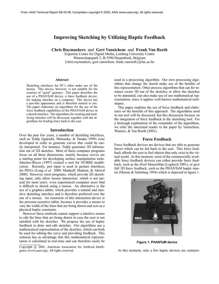
full 3D force feedback, such as the PHANToM haptic master (Massie & Salisburg 1994) which is depicted in figure 1.
Figure 1. PHANToM device
At this moment, only a few haptic devices are commer-
cially available. Most of the time, the PHANToM haptic
master is used in research and industry. To a lesser extend,
the FCS HapticMASTER (FCS Control Systems 2001) and
the Delta Haptic Device (Grange et al. 2001) are used as an
alternative for the PHANToM device. In our research, we
use the PHANToM device (as depicted in figure 1), which
provides 6D input and 3D output. Although the PHANToM
device is created for tasks in 3D space, it has successfully been used in 2D environments (e.g. Miller & Zelevnik
1998).
Force feedback, which is the mechanical production of information sensed by the human kinesthetic system (Oakley,
McGee, & Gray 2000) is a form of haptic feedback which
relates to the sense of touch. These terms are often interchanged.
This paper discusses the algorithms used to calculate the
forces which are fed back through the PHANToM device; a
more thorough explanation on haptic rendering can be found
in (Ruspini 1999).
Sketch Creation
In order to easily manipulate a sketch, the individual pixels
are grouped together into segments. Each of these segments
is represented by a cubic Bézier spline, as depicted in figure 2. The control points in this figure are shown for illustrative purposes only, our users are not confronted with these
control points; they directly manipulate the sketch.
The two other control points (B2 and B3 ) can be constructed by means of least square minimization (Vansichem,
Wauters, & Van Reeth 2001).
The use of force feedback helps to improve the “correctness” of the sketch: when using force feedback, one can be
sure that all pixels are taken into account. The input device
for the sketch creation has to be sampled by the program; for
common input devices, like the mouse, this sampling occurs
at a small rate, so when the user moves fast, the sampling
process can skip pixels, which leads to cruder sketches. On
the other hand, most force feedback devices are accessed in
a high-priority loop. This loop is executed at a rate of 1kHz
in order to generate realistic forces. Using a real-time operating system a rate of even 5kHz can be obtained (Kabelác̆
2000). The position of the force feedback device can also
be sampled in this loop, resulting in a smooth sketch, even if
the user moves very fast. Since the PHANToM device has a
sub-millimeter resolution (0.03mm), we do not use all sampled positions, but use a threshold to determine when a new
data point has to be created.
At this creation stage, force feedback is primarily used
to guide the user: a haptic plane is defined onto which the
user can draw the sketches. When the user presses harder
against this plane, a thicker line is drawn, like would happen
when using paper and pencil. Different surfaces can easily
be simulated by altering this resistance, an effect that cannot
be achieved using conventional input devices.
Controlling the Width
A planar constraint effect is used in order to restrict the
movement of the PHANToM device in the z direction. However the stylus can be moved slightly in the z direction by
exerting a force in this direction. This information is used to
determine the width of the curve: the harder the user pushes,
the wider the line is drawn. In contrast to the position of the
data points, which are determined using Bézier interpolation, the line width at the points is calculated using a linear
interpolation. The line width of the curve is thus represented
as set of interconnected line segments.
Figure 2. Sketch defined as segments
These cubic Bézier splines are defined by equation 1.
f (t) = (1−t)3 B1 +3t(1−t)2 B2 +3t2 (1−t)B3 +t3 B4 (1)
By applying curve fitting techniques, the pixels are added
to the current segment. Whenever the least square error of
the curve fitting passes a preset threshold, a new segment is
created. In order to provide smoothness of the sketch, two
subsequent segments share a number of pixels. A new segment is created by determining the control points B1 , B2 ,
B3 and B4 so that the difference between the spline and the
corresponding data points (P1 , P2 , . . . , Pn ) is as small as
possible. The start and end point (B1 and B4 ) of the spline
can be chosen in function of the above-mentioned smoothness represented by the parameter s: the number of shared
data points.
B1 = Ps
B4 = Pn−s
(2)
W = (1 − tw )W1 + tw W2
(3)
W1 and W2 represent the width at the start and end of
the segment. The tw value, which is used to determine the
width at the point, can be determined using the t value which
is used to calculate the position of the point, as described in
the previous section. But these values do not necessarily
have to be equal, which means that a Bézier segment can
contain more than one width segment. The calculation of
the line segments is based on a least square error. When the
calculated error is larger than a certain value, a new segment
is created. The W1 and W2 values of the new segment are
equal to the W2 value of the last segment, which provides a
smooth transition of the line width; otherwise the W2 value
of the current line segment is set equal to the width of the
last data point.
Editing
Currently, two major editing tools are implemented: local
modifications and transformations.
Local Modifications
Sometimes, the user is not entirely satisfied with the sketch
that is made. Instead of having to redraw the sketch, local
modifications can be made. Since we make use of cubic
Bézier splines, the problem of modifying a sketch can be
reduced to moving the control points of the segments. However, most people are not familiar with cubic Bézier splines
and find it hard to get the desired result. Therefore, our tool
lets the user pull and push against the curve. The control
points are transformed transparently in such a manner that
the modification of the sketch mimics the user’s movement,
thus allowing to intuitively redraw part of the sketch. We do
this by sketching the modification in the neighborhood of the
curve: the curve is pulled towards the pointer. This process
consists of three steps and is repeatedly executed during the
modification stage.
Selecting a Point on the Curve. To select the point nearest to the pen position we first need to determine the nearest Bézier segment. Since our tool makes use of OpenGL
for rendering, the OpenGL picking functionality can be
used (Woo et al. 1999). Next, the selected point on
the Bézier spline is determined by calculating the abovementioned t-value. This t-value is determined so that the
distance between the PHANToM position and the corresponding point is as small as possible.
The distance between the PHANToM position (x, y, z)
and the spline is given by:
g(t) = (x − fx (t))2 + (y − fy (t))2 + (z − fz (t))2
(4)
The desired t-value is found by solving the following
equation for t (Vansichem, Wauters, & Van Reeth 2001).
∂g(t)
=0
∂t
−
Modifying the Curve. Next, a vector →
V is defined:
(5)
−
→
V = (x, y, z) − (fx (t), fy (t), fz (t))
(6)
→
−
To adjust the Bézier segment, the vector V needs to be
−
distributed over its control points. The influence of →
V on
each of the control points is determined by the basis functions for a cubic Bézier spline. So the new control points
0
0
0
0
B1 , B2 , B3 and B4 are given by:
0
→
−
B1 = B1 + (1 − t)3 V
0
→
−
B2 = B2 + 3t(1 − t)2 V
0
→
−
B3 = B3 + 3t2 (1 − t) V
0
→
−
B4 = B4 + t V
(7)
In order to keep the smoothness at the transition from one
segment to another, the control points from the previous and
next segment will also be moved. We can distinguish three
different cases for the values of t:
1. t ≈ 0: Both the control points B1 and B2 of the selected
segment as well as B3 and B4 of the previous segment
−
will be moved over the distance →
V.
2. t ≈ 1: Both the control points B3 and B4 of the selected
segment as well as B1 and B2 of the next segment will be
−
moved over the distance →
V.
3. t ∈]0, 1[: B2 and B3 of the selected segment are moved
→
−
V
over 3t(1−t)
. The smoothness is preserved by rotating B3
of the previous segment around B1 of the selected segment and by rotating B2 of the next segment around B4
of the selected segment.
Haptic Feedback. When modifying a sketch, a force is
fed back to the user which resists the movement. This force
counterbalances the movement of the curve: the pointer is
−
drawn to the curve with a force (→
F ) proportional to the force
with which the curve is pulled to the pointer:
−
→
→
−
F = −l( V ).
(8)
→
−
The function l scales the magnitude of V in such a manner
that equation 9 is true.
→
−
0.2N ≤ k F k ≤ 1N
→
−
→
−
→
−
→
−
k V 1 k < k V 1 k ⇒ kl( V 1 )k < kl( V 1 )k
(9)
This force reduces errors by making large movements
harder to perform. On the other hand the forces that are
generated are never so big that they hinder (or fatigue) the
user.
Transformations
Most bitmap editors provide a selection tool and tools to
transform selections. Likewise, our tool provides a lasso selection tool. Unlike bitmap editors, the tool doesn’t select
the pixels within the selection area, but the control points
within the selection area. This allows for a more efficient
manipulation of the part of the sketch in which the user is
interested.
A number of tools are implemented which transform the
segments of which one or more control points are selected.
The selected area can either be translated, rotated or scaled
down. Because these tools work on the cubic Bézier splines
and not on individual pixels, the connectivity between the
curves is kept.
Again, force feedback can help when performing these
editing task: by defining different effects to counteract the
modifications, the user is guided during the manipulation
task. The force that counteracts the transformations is dependent of the curves that partially belong to the selection.
More exactly it is dependent on the first control points (B1
or B4 ) along the curves who are not part of the selection.
This way the force increases with the amount of curves that
connect the selected with the non-selected part of the sketch.
This makes it harder to move a selection that has a tight connection with its surroundings.
Figure 3. Rotation force at a point in time (the
pointer is indicated by the pencil in the upper left
corner)
Translation. The force is a scaled sum of the translations
of the mentioned control points:
−
→
V 1 = (x, y, z) − B1
→
−
V 4 = (x, y, z) − B4
→
−
→
−
→
−
F = −l( V 1 + V 4 )
(10)
Rotation. The size of the force is a scaled sum of the alleged translation of the mentioned control points. The direction is perpendicular to the vector from the center of the
rotation to the position of the pen. The calculation of the
counteracting force is depending on the type of transformation, as depicted in figures 3 and 4, which depict the rotation force at two moments during the interaction (rotating
the head of a cat).
Scale. The force is a scaled sum of the alleged scale of the
mentioned control points. These calculations are analogous
to the calculations in the translation case.
Additional Functionality
Next to creating a curve and modifying its position, we can
also define a wide range of additional tools, which can also
be implemented without exposing the mathematical structures to the user. In this paragraph we will shortly describe
some of these tools.
Eraser
Erasing a part of a sketch can be done by selecting the nearest point to the cursor with each move of the eraser. Subdividing the Bézier segment and width segment at this point
allows us to delete the part of the segment traversed by the
eraser without any changes to the rest of the sketch.
Figure 4. Rotation force (a few seconds later than
in figure 3)
The acting force works the same as with the creation of a
curve, only with a different scale according to the difference
in material (pencil versus eraser). This effect is achieved by
altering the resistance of the haptic plane. A pencil moves
more easily over a piece of paper than an eraser. An increase
in friction mimics this effect and decreases the number of
errors that are made because the user has more difficulties to
move the pointer of the friction is larger.
Connect Curves
An additional property of the drawing tools is the possibility
to automatically connect the start or end points of the newly
drawn curve to neighboring curves. With this addition it is
also possible to create closed curves.
The end point of the curve is snapped towards the begin
point if the pointer (thus the end point) comes in the vicinity
of the begin point. Likewise, the user feels an attracting
force towards the begin point:
−
→
V = P0 − (x, y, z)
→
−
→
−
→
−
k V k < M ⇒ F = l( V )
(11)
The begin point is indicated by P0 , the pointer position
by (x, y, z) and l is the function that was discussed in the
paragraph about editing. The parameter M defines a circle
in which the effect is felt. We can hereby control if the user
should feel the force before the curve is snapped to the begin
point.
This force also allows us to turn of the snapping of the
sketch, It is possible that the user wants to sketch near the
begin point, but does not want the sketch to snap. If only
the force is active, but not the sketch snapping, the user can
avoid this snapping effect by simply resisting the force.
Change Curve Width
Previously, a tool for correcting the position of the curve
was described. It is also possible to modify the width of the
curve. This is done again by selecting the nearest point to
the cursor on the curve. But instead of changing a Bézier
segment, the width segment will be modified by increasing
or decreasing the width at its start and/or end point. It is also
possible to subdivide the line segment when more level of
detail is needed.
The size of the width modification is dependent on the
pressure in the z direction exercised by the user. The maximum width is limited because the pressure of the user
against the plane is counteracted by a spring-damper system.
Future Work
Using force feedback, it is possible to mimic different types
of drawing surfaces, like paper or a blackboard. Although,
the research into this kind of haptic “textures” is still very
recent (McGee, Gray, & Brewster 2001), it is already incorporated into e-Touch (Novint 2001), a device-independent
haptic API.
These haptic textures can be combined with visual textures (e.g. a crayon-like texture) in order to get a truly “look
and feel” of different kinds of physical surfaces.
Conclusions
This paper discussed a tool for intuitively drawing sketches.
The tools uses an mathematical model for the sketch, without the user having to know this representation. This setup
provides the user with a powerful set of editing tools.
Special attention was paid to the use of force feedback.
This allows the user to efficiently create sketches and to
make corrections without have to redraw the entire sketch.
Acknowledgments
Part of the work presented in this paper has been funded
by the Flemish Government and EFRO (European Fund for
Regional Development).
References
FCS Control Systems. 2001. FCS HapticMASTER.
www.fcs-robotics.com.
Grange, S.; Conti, F.; Rouiller, P.; Helmer, P.; and Baur, C.
2001. Overview of the delta haptic device. In Proceedings
of Eurohaptics 2001, 164–166.
Igarashi, T.; Matsuoka, S.; and Tanaka, H. 1999. Teddy: A
sketching interface for 3D freeform design. In Proceedings
of the SIGGRAPH 1999 annual conference on Computer
graphics, 409–416. Los Angeles, CA, USA: ACM.
Kabelác̆, Z. 2000. Rendering stiff walls with PHANToM.
In Proceedings of the 2nd PHANToM Users Reserach Symposium 2000, volume 8 of Selected Readings in Vision and
Graphics.
Logitech. 2001. iFeel MouseMan. www.logitech.com.
Long, A. C.; Landay, J. A.; Rowe, L. A.; and Michiels, J.
2000. Visual similarity of pen gestures. In Proceedings
of CHI 2000, volume CHI 2000 Extended Abstracts, 360–
367. The Hague, NL: ACM.
Mankoff, J.; Hudson, S. E.; and Abowd, G. D. 2000.
Providing integrated toolkit-level support for ambiguity in
recognition-based interface. In Proceedings of CHI 2000,
volume CHI 2000 Extended Abstracts, 368–375. The
Hague, NL: ACM.
Massie, T. H., and Salisburg, J. K. 1994. The PHANToM
haptic interface: A device for probing virtual objects. In
Proceedings of the 1994 ASME International Mechanical
Engineering Congress and Exhibition, volume VOL DSC
55-1, 295–302. Chicago, IL, USA: ASME.
McGee, M. R.; Gray, P.; and Brewster, S. 2001. Feeling rough: Multimodal perception of virtual roughness. In
Proceedings of Eurohaptics 2001, 29–33.
Miller, T., and Zelevnik, R. 1998. An insidious haptic invasion: Adding force to the X desktop. In Proceedings of the
11th annual ACM symposium on User interface software
and technology, 59–66. San Francisco, CA, USA: ACM.
Novint. 2001. e-Touch. www.novint.com.
Oakley, I.; McGee, M. R.; and Gray, S. B. P. 2000. Putting
the feel in ’look and feel’. In Proceedings of CHI 2000,
415–422. The Hague, NL: ACM.
Ruspini, D. 1999. Haptics: From Basic Principles to Advanced Applications. Number 38 in Course Notes for SIGGRAPH ’99. ACM. chapter Haptic Rendering.
Sánchez-Reyes, J. 1997. A simple technique for nurbs
shape modification. IEEE Computer Graphics and Applications 17(1):52–59.
Vansichem, G.; Wauters, E.; and Van Reeth, F. 2001.
Real-time modeled drawing and manipulation of stylized
cartoon characters. In Proceedings of the IASTED International Conference on Computer Graphics and Imaging,
44–49. Honolulu, HI, USA: IASTED.
Woo, M.; Neider, J.; Davis, T.; and Shreiner, D. 1999.
OpenGL Programming Guide. Addison-Wesley, 3 edition.

