From: AAAI Technical Report SS-02-08. Compilation copyright © 2002, AAAI (www.aaai.org). All rights reserved.
A Multi–Level Sketching Tool for “Pencil–and–Paper” Animation
Fabian Di Fiore and Frank Van Reeth
Expertise Centre for Digital Media – Limburg University Centre
Wetenschapspark 2, B–3590 Diepenbeek
Belgium
{fabian.difiore, frank.vanreeth}@luc.ac.be
Abstract
Computer assisted traditional animation has gained a lot of attention nowadays. Although most existing software applications turn out to produce appealing results, still the animator
has to cope with many limitations. So far, animators have to
make great efforts when interacting with the software. Most
drawings consist out of curves which only can be manipulated
by pointing, clicking and dragging of control points which
make up the curves. Moreover, most systems don’t offer a
surplus value and hence it is difficult to convince animators to
make the shift to computer assisted animation. In this paper,
we present a sketching tool that assists the animator throughout multiple stages of the animation process. This tool helps
retaining the natural way of drawing and editing, and offers
additional functionality such as rapidly creating approximate
3D models and deforming animation objects.
Keywords: sketching, free–form strokes, traditional animation, 2D animation, character animation, computer assisted animation.
(a)
(b)
(b)
Figure 1. Some typical animation characters. a) A
smiling dog. b) A cute animation girl. c) A joyful
runner.
how to manipulate the control point in order to achieve the
desired result he is bearing in mind.
Introduction and Motivation
When we talk about animation in the context of this paper
we refer to animations where the objects and characters are
hand–drawn and resemble real life but do not mimic reality
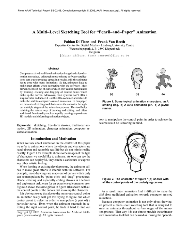
exactly. Figure 1 for example shows some images of the type
of characters we would like to animate. As one can see the
characters can be playful, they can be a caricature or express
any other artistic feeling.
When looking at existing developments, the animator still
has to make great efforts to interact with the software. For
example, most drawings are made out of curves which only
can be manipulated by “point–click–and–drag”–procedures.
Hence, creating and especially editing strokes is a tedious
and unpleasant task, even for an experienced computer user.
Figure 2 shows the same girl as in figure 1(b) shown with all
the control points of the curves that make up the character.
It is obvious to see that due to the numerous control points
an animator easily will get lost trying to figure out which
control point to select in order to manipulate (a part of) a
particular curve. Even when the animator succeeds in selecting the right control point, he finds it hard to find out
c 2002, American Association for Artificial IntelliCopyright gence (www.aaai.org). All rights reserved.
Figure 2. The character of figure 1(b) shown with
all the control points of the underlying curves.
As a result, most animators find it difficult to make the
shift from traditional animation towards computer assisted
animation.
Because computer animation is not only about drawing,
we present a multi–level sketching tool that is designed to
assist an animator throughout various stages of the animation process. That way it is our aim to provide the animator
with an intuitive tool that can be used as if using the “pencil–
and–paper” approach. We focus on its use as a tool for (i)
creating, editing and transforming strokes which make up
the drawn objects, (ii) rapidly creating approximate 3D models which depict the volume of the objects to be drawn, and
(iii) performing high–level operations such as free–form deformations.
This paper is organized as follows. The next section gives
an overview of related work, while the following sections
elaborate on our approach and results. We end with our conclusions, topics for ongoing future research and some acknowledgements.
Related Work
By providing the animator with a multi–level sketching tool,
our approach enriches traditional computer assisted animation at various stages of the animation process. This section elaborates on free–form strokes, techniques to create
and manipulate simple 3D objects and some approaches to
perform free–form deformations.
Free–Form Strokes
In recent years, the use on free–form strokes for creating 2D
free–form objects has become popular.
In 1994 (Hsu & Lee 1994) presented an animation system for producing 2.5D animations using skeletal strokes as
the basic primitive. In their paper, skeletal strokes can be
regarded as a realization of the brush and stroke metaphor
using arbitrary pictures and its deformations as ink. Since
any arbitrary picture can be defined to be a skeletal stroke,
a huge variation in styles is possible. However, the animator still has to cope with a lot of additional work (providing
input images and deforming images (Hsu, Lee, & Wiseman
1993)) in comparison with traditional animation.
More recently, (Vansichem, Wauters, & Van Reeth 2001)
proposed an approach for drawing and manipulating stylized
curves without the need to explicitly manipulate (i.e. point,
click and drag) control points of underlying splines. Their
approach generates curves on–the–fly by processing (pressure sensitive) stylus data at real–time. This simplifies the
interaction drastically because the animator can exploit direct manipulation tools on the curves themselves.
We use a similar technique as described by (Vansichem,
Wauters, & Van Reeth 2001) because this comes very close
to the sketching method that traditional animators tend to
use.
Techniques to Rapidly Create Simple 3D Objects
Free–form strokes are also being used for rapidly designing
3D free–form objects.
(Igarashi, Matsuoka, & Tanaka 1999) present a gesture–
based sketching interface (TEDDY) to quickly and easily
design 3D free–form models out of 2D sketched strokes. In
their system the designer first interactively draws 2D free–
form strokes depicting a 2D silhouette. A 3D polygonal object is automatically constructed by inflating the region surrounding the silhouette, making wide areas fat and narrow
ones thin.
(Bimber 1999) describes a system that extends this
sketching interface by supporting dynamic gesture recognition. A particular grammar extracts the required information
on the fly.
Our work shares parts of their core ideas, such as the use
of free–form strokes to draw the outlines and working with
simplified models.
Free–Form Deformation
As the use of our sketching tool includes performing freeform deformations of objects, we briefly highlight some related work in the field.
In 1986 (Sederberg & Parry 1986) presented a technique
for deforming solid 3D geometric models in a free–form
manner. First, a local coordinate system is imposed on a
parallelpiped region. Next, they impose a grid of control
points on the parallelpiped region. That way the deformation is specified by movements of the control points. In fact,
mathematically, the deformation function is defined in terms
of a tensor product trivariate Bernstein polynomial in which
the coefficients of the Bernstein polynomial are actually the
control points of the grid.
(Coquillart & Jancène 1991) proposed an interactive technique for animating deformable objects. They provide an alternative to the metamorphosis method that often is used to
create intermediary shapes in order to make a smooth transition between two key–shapes. This technique, Animated
Free–Form Deformation, relies on the Free–Form Deformation technique described in (Sederberg & Parry 1986).
Since we are only interested in deforming solid geometric
models, we will make use of a 2D adapted version of the
free–form deformation technique.
Multi–Level Sketching Tool
In this section, we introduce a multi–level sketching tool as
a helpful means assisting the animator throughout various
stages of the animation process. We successively show how
this tool can be used to (i) create and manipulate strokes
which make up the final drawing, (ii) rapidly and easily construct approximate 3D models, and (iii) deform animation
characters.
Free–Form Strokes
When drawing, in traditional animation, the most striking
characteristic is the freedom the animator has. He can easily
draw all kinds of stylish curves on paper just by using one
pencil, he dynamically can alter the width and the curvature
of the curves and moreover, when the animator is not satisfied with the result, he can make (simple) corrections just by
drawing new curves along or on top of the “wrong” ones.
Figure 3 shows a sketched drawing of a cute dog as a traditional animator is likely to draw it.
Our basic aim in this context is to support the animator in
the creation and manipulation of the curves representing animation characters, of course without having to take recourse
to “point–click–and–drag” metaphors.
Therefore we introduce a sketching tool which allows for
intuitive drawing of cartoon figures.
transforming the underlying curve representation of the targeted stroke in such a way that it reflects the user’s intentions.
Manipulations on the splines are actually performed on
their control points, but this happens transparently for the
user. The control points are never shown in the user interface.
Figure 5 shows the dog of figure 3 drawn with our sketching tool.
Figure 3. A sketched drawing of a cute dog as an
animator is likely to draw it.
The creation of a curve is done interactively by sampling
a (not necessarily) pressure sensitive stylus along the trail of
the stroke. In order to allow for real–time high–level manipulations on the sketches, the individual pixels that make up
the sketch are not used. Instead, a high–level representation,
using cubic Bézier splines, is made, as is illustrated in figure
4.
Figure 5. The same dog as in figure 3 drawn with
our sketching tool.
Aside the creation and editing of free–form strokes, we
also added support for performing affine transformations
upon (selections of) strokes.
Notice that the animator does not have to worry about
picking, clicking and dragging control points associated
with the underlying curve primitives. That way we preserve
the same freedom of drawing an animator has when using
the “pencil–and–paper” approach.
Figure 4. Sketch created with our sketching tool
(shown with control points).
The creation of a curve is as follows. While sampling a
pressure sensitive stylus we simultaneously perform an iterative curve fitting technique based on least–squared–error
estimation. Existing curve drawing solutions mostly take recourse to a “batch” curve fitting solution, in which the fitting
is done after the stroke drawing is finished, whereas our fitting is done on–the–fly while the curve is being sketched.
Once the underlying curve is created, it can be edited
upon. The conventional interaction metaphors are based
upon explicitly “point–click–and–drag” the control points.
Our solution mimics the sketching method used by artists
when sketching strokes with a pencil on paper: the stroke is
edited upon by moving the pressure sensitive stylus alongside (a part of) an existing stroke. These movements are
sampled and are consequently interpreted as an attractor
Approximate 3D Models out of 2D Strokes
When looking at the traditional production process (Blair
1994), animators first make reference drawings, which contain proportion guidelines, of the separate objects.
Afterwards, the key poses of all the characters are created,
thereby referring to the reference images in order to retain
the proportions. This latter step is usually done by (i) constructing the characters from circular and rounded “3D–ish”
forms (see figure 6(a)) that support the animator in retaining
the volume of the characters throughout the entire production, and (ii) drawing outlines of the characters by making
sketches along the silhouettes of the rounded shapes (see figure 6(b)).
In a following stage, the so–called inbetween frames are
drawn.
It is obvious that this traditional procedure is unmanageable and that mistakes are quickly made.
With our sketching tool, we propose to enhance these conventional working practices in the creation of key poses.
(a)
(b)
c 1994 Preston Blair. a) A
Figure 6. Copyright drawing of a cat constructed from circular and
rounded forms. b) The same cat after inking the
outlines.
(The generation of inbetween frames is a completely different problem, which is outside the scope of this paper. The
reader interested in how we implemented the inbetweening
stage is referred to (Di Fiore et al. 2001).)
For generating the outlines of step (ii), the techniques described in the previous subsection (“Free–Form Strokes”)
are utilized.
The functionality of step (i) is provided as follows. First,
the user sketches (and possible modifies) 2D circular and
rounded forms (input strokes) as if drawing on paper. We
use our sketching tool to create and alter these 2D objects,
so the forms consist out of a collection of free–form strokes.
Our system then interprets these circular and rounded
forms to automatically construct a 3D polygonal object of
revolution. This approach is considerably more simplified as
compared to the methods described in (Igarashi, Matsuoka,
& Tanaka 1999) and (Bimber 1999), but is sufficient to support the construction of the plain approximate shapes that
traditional animators tend to use.
For example, drawing an ellipse generates an elliptical 3D
object.
Figure 7 shows our version of the character of figure 6.
As you can see in figure 7(a) we only show the silhouettes
(Claes et al. 2001) of the 3D objects as they are much more
similar to the 2D rounded and circular forms than, for example, a shaded version of the 3D object. The outlines in figure
7(b) have been drawn by the animator using the sketching
tool as described in previous subsection.
We also added support for modifying the 3D objects and
performing affine transformations upon them. This can be
regarded as performing these transformations upon the input strokes and so this is similar to transforming free–form
strokes (as explained in previous subsection) and needs no
further explanation.
It is clear that animators prefer this kind of interaction,
which comes very close to the traditional way of working,
instead of working, for example, with an application specifically designed for modelling 3D objects.
To summarize, in this section we explained how to easily create approximate 3D models by mimicing conventional
working practices. We showed how this effectively can be
achieved by simply creating 2D free–form strokes created
(a)
(b)
Figure 7. a) The same cat as shown in figure 6(a)
constructed from approximate 3D objects created
with our sketching tool. b) Our results by inking
the outlines using our system.
with our sketching tool.
Free–Form Deformation Tool
In the previous sections we showed how our sketching
tool provides a very effective means to assist the animator
throughout the drawing stage when creating an animation.
In this section we explain the use of the same sketching
tool as an aid to deform in a free–form manner 2D objects
consisting out of free–form strokes. It is our aim to indicate that an animator can deform objects without having to
fall back on complicated deformation programs that are not
intuitive to use at all.
As it was the case for free–form strokes, we differentiate
between a lower level representation which is hidden for the
user and which basically performs the actual deformation,
and a higher level representation which allows the animator
to do real–time intuitive manipulations.
In our approach, the higher level representation consists
of two strokes: one that represents the initial state of the
object, and a second one that indicates how the object should
be deformed. The lower level representation includes the
control points of the curves which make up the object, the
underlying structure of the two higher level strokes and the
control points of a 2D grid.
In order to deform an object, our system first puts an
evenly spaced 2D grid of control points Gij on the object.
Then, the user sketches the first stroke (source stroke) upon
(part of) the object. This represents the current state of the
object. Now a second stroke (deformation stroke) is drawn,
which can be seen as a deformation of the source stroke.
Actually, this stroke indicates the desired deformation of the
object.
The deformation algorithm is as follows. Our system first
divides both strokes into N segments and maps these onto
each other. Next, every control point of the grid that lies
within a specific distance relative to the source stroke, is assigned to the nearest segment of this stroke.
For each segment s of the input stroke we also store the
transformation t which is defined by transforming segment
s of the source stroke to the corresponding segment s0 of the
deformation stroke.
Then, for each segment s, all assigned control points undergo the stored transformation t.
Finally, for each control point of the underlying curves of
the object, we calculate its deformed position by using the
deformation function (adapted for the 2D case) described
in (Sederberg & Parry 1986) and as a result the object gets
deformed.
All of this is hidden and happens transparently for the
user, except for drawing the source and deformation stroke.
Figure 8 gives an example of a free–form deformation of
a lamppost.
One possible way is to make use of “gesture” widgets:
gestures that are turned at run–time into widgets. That way
we can provide an intuitive and accurate interface for manipulations in sketching interfaces.
Acknowledgements
We gratefully express our gratitude to the European Fund
for Regional Development and The Flemish Government,
which are kindly funding part of the research reported in
this paper.
Many thanks to Liesbeth Beckers and “Xemi” Morales for
their artistic contribution.
Furthermore we would like to acknowledge ANDROME
R pluNV for freely putting available to us their CreaToon
gin SDK.
References
(a)
(b)
(c)
Figure 8. a) Original lamppost. b) Deformed lamppost. c) Source and deformation stroke.
We conclude this section by stating that our multi–level
sketching tool enables the animator to perform free–form
deformations just by drawing two strokes which is very easy
and intuitive.
Conclusions and Future Research
In this paper, we presented the use of a multi–level sketching tool as a powerful tool to assist the animator throughout
various stages of the drawing process when creating an animation.
Animators still have to cope with a lot of limitations when
using existing software applications. Drawings consist out
of curves but these can only be manipulated by “point–
click–and–drag”–procedures. This is a very difficult and tedious process and feels anything but natural. Together with
the fact that these systems don’t offer a surplus value causes
animators not to make the shift from traditional to computer
assisted animation.
We showed how the multi–level sketching tool can be
used to overcome these problems. We successively described how to create drawings by using free–form strokes,
how to rapidly create approximate 3D models and how to
perform high–level operations such as free–form deformations.
In future research, we want to investigate the interface that
is needed to transform a sketch. We thus need an intuitive
user interface for rotating, translating and scaling sketches.
Bimber, O. 1999. Rudiments for a 3D freehand sketch
based human–computer interface for immersive virtual environments. In Proceedings of VRST ’99, 182–183. ACM.
Blair, P. 1994. Cartoon Animation. Walter Foster Publishing Inc., ISBN: 1–56010–084–2.
Claes, J.; Di Fiore, F.; Vansichem, G.; and Van Reeth, F.
2001. Fast 3D cartoon rendering with improved quality
by exploiting graphics hardware. In Proceedings of Image
and Vision Computing New Zealand (IVCNZ) 2001, 13–18.
IVCNZ.
Coquillart, S., and Jancène, P. 1991. Animated free–form
deformation: An interactive animation technique. In Proceedings of SIGGRAPH ’91, 23–26. ACM.
Di Fiore, F.; Schaeken, P.; Elens, K.; and Van Reeth, F.
2001. Automatic in–betweening in computer assisted animation by exploiting 2.5D modelling techniques. In Proceedings of Computer Animation 2001, 192–200.
Hsu, S. C., and Lee, I. H. H. 1994. Drawing and animation
using skeletal strokes. In Proceedings of SIGGRAPH ’94,
109–122. ACM.
Hsu, S. C.; Lee, I. H. H.; and Wiseman, N. E. 1993. Skeletal strokes. In Proceedings of UIST ’93 of the ACM SIGGRAPH & SIGCHI Symposium on User Interface Software
& Technology, 109–118. ACM.
Igarashi, T.; Matsuoka, S.; and Tanaka, H. 1999. Teddy: A
sketching interface for 3D freeform design. In Proceedings
of SIGGRAPH ’99, 409–416. ACM.
Sederberg, T. W., and Parry, S. R. 1986. Free–form deformation of solid geometric models. In Proceedings of
SIGGRAPH ’86, 151–160. ACM.
Vansichem, G.; Wauters, E.; and Van Reeth, F. 2001.
Real–time modeled drawing and manipulation of stylized
cartoon characters. In Proceedings of the IASTED International Conference on Computer Graphics and Imaging,
44–49. IASTED.


