From: AAAI Technical Report SS-94-05. Compilation copyright © 1994, AAAI (www.aaai.org). All rights reserved.
Computer Assisted
P. Sautot, S. Lavallee,
J. Troecaz, P. Cinquin
TIMC, Faculte de Medecine de Grenoble
38706 La Tronche CEDEX FRANCE
Pascal.Sautot @timb.imag.fr
Spine Surgery
P. Merloz
de Chirurgie Orthopedique
CHU Grenoble,
38700 La Tronche FRANCE
Service
Abstract
Computerassisted spine surgery follows the basic ideas
developedfor ComputerAssisted Medical Intervention
(CAMI).Quantitative analysis of medical imagesmakes
it possible to localize with great accuracy anatomical
structures. This is fruitfully used to drive guidingsystems. This methodtends to minimize invasive surgery
and increases the quality of surgical interventions. In
this article we present our methodologyand develop
someresults leading to clinical experimentations.
Introduction
Spine is madeof 24 articulated vertebrae. Instrumentation maybe neededto fix spine segments,in order to
reduce deformities (e.g. scoliosis) or fractures. Spinal
surgery instrumentation basically consists in three implantable elements: the rod, the hook and the screw
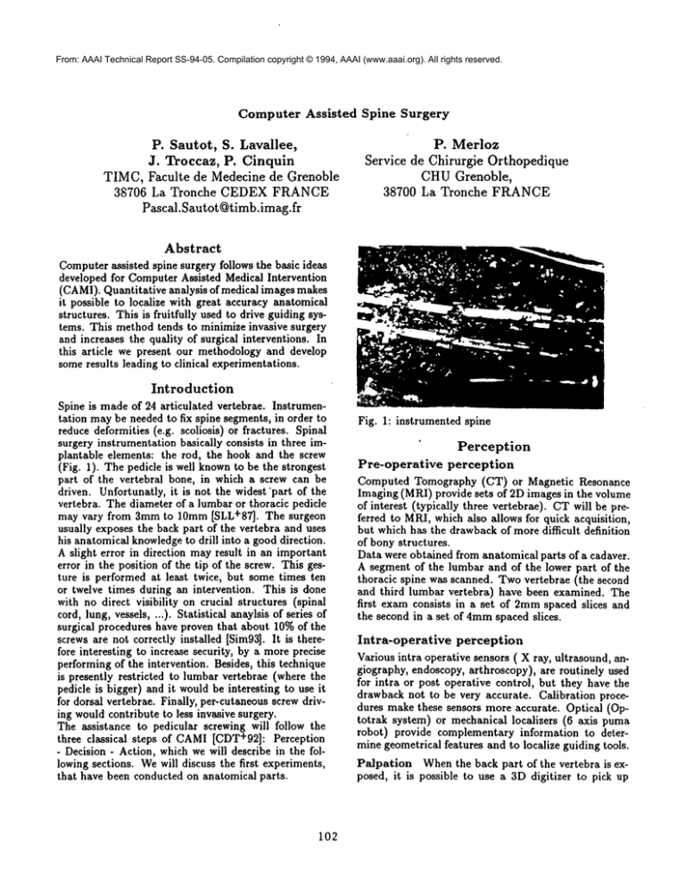
(Fig. 1). The pedicle is well knownto be the strongest
part of the vertebral bone, in which a screw can be
driven. Unfortunatly, it is not the widest’part of the
vertebra. The diameter of a lumbaror thoracic pedicle
may vary from 3mmto 10mm[SLL+87]. The surgeon
usually exposesthe back part of the vertebra and uses
his anatomicalknowledgeto drill into a gooddirection.
Aslight error in direction mayresult in an important
error in the position of the tip of the screw. This gesture is performedat least twice, but sometimes ten
or twelve times during an intervention. This is done
with no direct visibility on crucial structures (spinal
cord, lung, vessels, ...). Statistical anaylsis of series of
surgical procedures have proven that about 10%of the
screwsare not correctly installed [Sim93].It is therefore interesting to increase security, by a moreprecise
performingof the intervention. Besides, this technique
is presently restricted to lumbarvertebrae (where the
pedicle is bigger) and it wouldbe interesting to use it
for dorsal vertebrae. Finally, per-cutaneousscrew driving wouldcontribute to less invasive surgery.
The assistance to pedicular screwing will follow the
three classical steps of CAMI[CDT+92]:Perception
- Decision- Action, whichwewill describe in the followingsections. Wewill discuss the first experiments,
that have been conductedon anatomical parts.
102
Fig. 1: instrumented spine
Perception
Pre-operative
perception
Computed Tomography (CT) or Magnetic Resonance
Imaging (MRI)provide sets of 2D images in the volume
of interest (typically three vertebrae). CTwill be preferred to MRI,whichalso allows for quick acquisition,
but whichhas the drawbackof moredifficult definition
of bonystructures.
Data were obtained from anatomical parts of a cadaver.
A segment of the lumbar and of the lower part of the
thoracic spine was scanned. Twovertebrae (the second
and third lumbar vertebra) have been examined. The
first examconsists in a set of 2ramspaced slices and
the second in a set of 4mmspaced slices.
Intra-operative
perception
Variousintra operative sensors ( X ray, ultrasound, angiography, endoscopy,arthroscopy), are routinely used
for intra or post operative control, but they have the
drawbacknot to be very accurate. Calibration procedures makethese sensors more accurate. Optical (Optotrak system) or mechanical localizers (6 axis puma
robot) provide complementaryinformation to determinegeometricalfeatures and to localize guiding tools.
Palpation Whenthe back part of the vertebra is exposed, it is possible to use a 3Ddigitizer to pick up
the 3D coordinates of the visible surface of the vertebra (Fig. 2). Wehave used an Optotrak system, which
makes it possible to get the coordinates of the tip of a
pointer with about 0.2 mmof accuracy. It is very easy
to pick up about 100 points, which has proven sufficient
for later registration.
reflexion of ultrasounds. However, we only need the
external part of the vertebra, and may therefore use
this technique [BTML93].It is necessary to know the
spatial position of all the pixels that may be seen on
the ultrasonic images. Wehave therefore equipped the
ultrasonic probe with diodes, that make it possible for
the Optotrak system to locate with great accuracy the
position and orientation of the ultrasonic slice (Fig. 4).
There again, per cutaneous techniques may be applied.
Fig. 4: Ultra sound probe
Decision
Fig. 2: optotrak digitizer
X rays A classical portable X ray device is used (Fig.
3). Several views can be acquired by moving the X ray
~ource around the spine. The advantage of this sensor
s that it maybe used for per cutaneous surgery. It puts
~ome calibration problems, that have been overcome by
1sing camera calibration methods [CLSC92]. Wehave
teveloped special calibrating plates for accurate regis.ration. The first assumption is that the vertebra does
~ot moves. This can be verified in the lumbar region.
n the thoracic region the rib cage may move. This
Lrtefact can be corrected using a 3D localizer. Each
ime an image is acquired, we store the position of the
,ertebra and the position of a calibration imagerelative
o an absolute reference coordinate system. So, we can
~pply the method previously mentionned method.
Image Analysis
The classical taxonomy for 2d segmentation distinguishes two kinds of techniques: contour based or region
based methods. It can be extended in three dimensions
by surface based or volume based methods. Segmentation of medical images often relies on a priori knowledge
and interactive procedures. Wehave developed several
deformable surface tools, that are used to modelize preoperative images with minimal interaction with the user
(Fig. 5). These tools create an isotropic segmentedvolumeof data, which is used for later registration.
Fig. 5: 3D smoothed surface of the vertebra
Surgical
Planning
Before performing the intervention, relying on the use
of medical images, surgeons choose an optimal surgical strategy. In the litterature, several quantitative parameters are proposed to describe a vertebra [SLL+87].
These parameters can be related to direct measurements on CT scan images [OSK+90]. It, has encouraged
ig. 3" X ray device
Iltrasounds Ultrasonic images of bony structures
re known to be very poor, because of the specular
103
us to design a user interface to plan the position of a
screw inside a pedicle. CTslices are used to determine
this situation. The software visualizes three perpendicular sections passing through the axis of the pedicle
and allows to select a trajectory represented by a set of
two points in the CT frame reference system PlcT=
(zl, yl, zl, 1)’ P2CT= (z2, y2, z2, 1)’ (Fig.
the Optotrak (Fig. 7). The axis of the tool is calibrated
and represented by a line segment(PlD,’iller,P2D,-iUe,.).
An adequate user interface provides the surgeon with
information about the position of the drill, and helps
him go into the previously defined direction.
Fig. 6: surgical planning
The strategy to drill through the pedicle consists in superimposing the line segment (Plz),in~,,P2Drin~,) with
the line segment (Plse,°or,P2s~n,o,).
Three screws
have been introduced succesfully. Quantification of the
accuracy of this introduction will soon become available.
Registration
Given sensed data in the intra operative sensor coordinate system, and modelled data in the pre-operative
model coordinate system, registration
estimates the
rigid transformation TCT,o, (4 x 4 rigid transformation homogeneousmatrix) that aligns sensed data with
the model. Wehave developed efficient distance maps
and implemented least squares algorithms, which are
adaptative By nature and converge near a global minimum(that may be found with a very limited apriori
knowledge) and that ensure a good accuracy [BL92]
[LSB91]. The same algorithm can be applied to 3D/3D
and 2D/3Dregistration. The first case applies to registration between CTand ultrasonic or palpation data.
The second one corresponds to registration between CT
and radiographic data (which are only 2 dimensional).
All these techniques require about 3s, with a Digital
DS5000. Once the pre operative and intra operative
reference system have been registrated the pre operative trajectory is transformed in the intra operative reference coordinate system as follows Pis~n,or= T~ensorCT
PiCT.
Fig. 7:the driller
Semi Passive
and the exprimental setup
Systems
Semi passive systems differ by their ability to deliver a
precise mesure of the action beeing currently performed.
A robot carries a laser beam, that indicates the correct
direction. An alignment device set on the driller makes
it possible for the surgeon to drill into the correct direction. A simulation of that system has been realized
Weare currently developing a prototype of a surgical
system (Fig. 8).
Action
Screw may be guided towards the pedicle through passive or semi-passive aids.
Passive
System
Purely passive systems provide a means to compare the
current action with a previously planned strategy. Information has to be interpreted by the surgeons. A
driller is equipped with diodes, that makeit visible by
104
C.Barbe,
B.Mazier,
R.Orti
fortheircontribution
to this
work.
[BL92]
References
L. Brunie and S. Lavallde. Threedimensionnal
dynamic
imaging
of thespine.
In MEDINFO 9~, Geneve, Switzerland,
September
1992.
[BTML93] C. Barbe, J. Troccaz,B. Mazier,and
S. Lavallee.
Using2.5Dechography
in computerassisted
spinesurgery.
In IEEE,pages
160-161,
SanDiego,1993.@embs.
[CDT+92]P. Cinquin,J. Demongeot,J. Troccaz,
S. Lavallde,
G. Champleboux,
L. Brunie,
F. Leitner,
P. Sautot,
B Mazier,
A. Pdrez,
M. Djaid,T. Fortin,
M. Chenin,
andChapel
A. Igor: Imageguidedoperating
robot:
methodology,
medical
applications,
results.
ITBM (Innovation and Technology in Biology and Medicine) - Special Issue on Robotic
Surgery, 13(4):373-393, 1992.
[CLSC92]G. Champleboux, S. Lavallde, P. Sautot,
and P. Cinquin. Accurate calibration
of
cameras and range imaging sensors, the
NPBS method. In IEEE Int. Conf. on
Robotics and Automation, pages 1552-1558,
Nice France, May 1992.
rig.8:therobotandthecalibration
plate
’~ig.9:anX rayimageof 2 screws
inside
pedicles
Conclusion
~xperiments have been conducted on cadaver (Fig. 9)
.nd plastic vertebrae. Simulations showedthat sub milimetric accuracy may be obtained, by any of the com,ination of the above mentioned perception and action
levices. Wehave just validated all the pre operative
teps. We are currently preparing the validation of
he intra operative steps and improving the registraion procedure. 2D/3D registration uses the contours
.f the shape of the vertebra. Theyare quite difficult to
,e determined. We propose a method which will take
ato account the probabilty of a pixel to belong to conour. This probability depends on pixel attributes such
s gradient value, gray level value,... First experiments
n humanbeings will be planned by the middle of 1994,
’.’our results meet the surgical requirements.
Acknoledgements
?hisresearchhas beenpartially
supported
by So~mor(Berck,France).
We thankF.Leitner,
E.Bainville,
105
[LSB91] S. Lavallde, R. Szeliski, and L. Brunie.
Matching 3-D smooth surfaces with their 2D projections using 3-D distance maps. In
SPIE Vol. 1570 Geometric Methods in Computer Vision, pages 322-336, San Diego,
CA, July 1991.
[OSK+90] J.M. Olsewski, E.H. Simmons, F.C. Kallen,
F.C. Mendel, C.M. Severin,
and D.L.
Berens.
Morphometry of the lumbar
spine : anatomical perspectives related to
transpedicular
fixation.
The Journal of
Bone and Joint Surgery, 72-A(4):541,548,
1990.
E. Sire.Location
of transpedicular
screws
[Sim93]
fixation
of the lowerthoracic
andlumbar
spine.ActsOthopScand,64(1):28-32,
1993.
[SLL+8~ P.V.Scoles,
A.E.Linton,
B. Latimer,
M.E.
Levy,and B.F.Giovanni.Vertebralbody
and posterior
elementmorphology
in the
normal adult spine. In ~th proceeding of the
international congress on Cotrel Dubousset
instrumentation, pages 151-156, Montpellier, 1987. Sauramps Medical.


