Development Static Switch Distributed of a High-Speed
advertisement
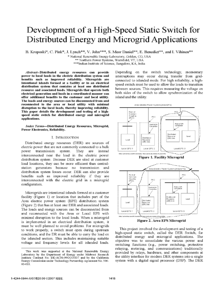
Development of a High-Speed Static Switch for Distributed Energy and Microgrid Applications B. Kroposki*, C. Pink*, J. Lynch**, V. John***, S. Meor Daniel"*, E. Benedict**, and I. Vihinen** * National Renewable Energy Laboratory, Golden, CO, USA * * Northern Power Systems, Waitsfield, VT, USA * * *Indian Institute of Science, Bangalore, KA, India Depending on the switch technology, momentary interruptions may occur during transfer from gridconnected to islanded mode. For high reliability, a highspeed switch must be used to allow the loads to transition between sources. This requires measuring the voltage on both sides of the switch to allow synchronization of the island and the utility. Abstract--Distributed energy resources can provide power to local loads in the electric distribution system and benefits such as improved reliability. Microgrids are intentional islands formed at a facility or in an electrical distribution system that contains at least one distributed resource and associated loads. Microgrids that operate both electrical generation and loads in a coordinated manner can offer additional benefits to the customer and local utility. The loads and energy sources can be disconnected from and reconnected to the area or local utility with minimal disruption to the local loads, thereby improving reliability. This paper details the development and testing of a highspeed static switch for distributed energy and microgrid applications. Area Electric Power System (Area EPS) PCC Point of Common P00 Coupling (PCC) Point of DR .o,~tof DR . Connection Index Terms-Distributed Energy Resources, Microgrid, Power Electronics, Reliability. I. INTRODUCTION Distributed energy resources (DER) are sources of electric power that are not commonly connected to a bulk power transmission system. They are instead interconnected near the load in the electric power distribution system. Because DER are sited at customer load locations, they can be more efficient than centralstation generators because no transmission and distribution system losses occur. DER can also provide benefits such as improved reliability if they are interconnected with the electric grid in a microgrid configuration. Microgrids are intentional islands formed at a customer facility (Figure 1) or location that includes part of the Area electric power system (EPS) distribution system (Figure 2) that has at least one DER and associated loads. The loads and energy sources can be disconnected from and reconnected with the Area or Local EPS with minimal disruption to the local loads. When a microgrid is implemented in an electrical distribution system, it must be well planned to avoid problems. For microgrids to work properly, a switch must open during upstream conditions, and the DR must be able to carry the load on the islanded section. This includes maintaining suitable voltage and frequency levels for all islanded loads. ~~~~~Connection.l Distributed Resource (DR) Unit Distributed Resource (DR) Unit Load Local EPS 1 Local EPS 2 Load Local EPS 3 Nte: Dashed Hie ar EPS boundaris. Th- cn be any nmbr of L. IEPSs * Figure 1. Facility Microgrid - Area Electric Power System (Area EP - PCC Point of Common oupling (P00) Point of DR . .} Point of DR . Connection Distributed Resource (DR) Unit Load Local EPS 1 ~~~~~~Connection Distributed Resource (DR) Unit Local EPS 2 Load Local EPS 3 ...'. Note: Dashed Hine are EPS bonais ...ee a be any number of L...al EPSs Fiur 2. ---------EPS _,_-- _.-.-------- M Figure 2. Area EPS Microgrid This project involved the development and testing of a high-speed static switch, called the DER Switch, for distributed energy and microgrid applications. The objective was to consolidate the various power and switching functions (e.g., power switching, protective relaying, metering, and communications) traditionally provided by relays, hardware, and other components at the utility interface for modem DER systems into a single system with a digital signal processor (DSP). The DER This work was supported at the National Renewable Energy Laboratory by the Department of Energy under Midwest Research Institute Contract No. DE-AC36-99GO10337 and by the California Energy Commission under Technology Partnership Agreement No. 50003-011. 1-4244-0844-X/07/$20.00 ©2007 IEEE. ''; -'''"'""'""''........ 1418 Switch is designed to meet Institute of Electrical and Electronics Engineers (IEEE) 1547 [1] and Underwriters Laboratories 1741 [2] grid interconnection standards to minimize custom engineering and site-specific approval processes and, therefore, lower cost. To maximize applicability and functionality, it was also designed to be technology-neutral therefore, the DSP controls can be used with circuit breakers (CBs) as well as with faster semiconductor switching technologies such as siliconcontrolled rectifiers (SCRs), insulated gate bipolar transistors (IGBTs), and integrated gate commutated thyristors (IGCTs) and applicable to DER assets with conventional generators or power converters. * Offer a fully functional and demonstrated energy management interface. The objective of this research was to design, build, and test a working DER Switch prototype that met as many of these goals as possible, given limited time, funding, and data on traditional solutions and the maturity of low-cost products available in the market today. The key measures of success were a prototype DER Switch that (1) integrated all control and protection functions typically performed by relays and other hardware; (2) had the ability to meet relay, IEEE 1547, and power quality and other performance goals; and (3) could be offered at a reduced cost. Technology-neutral design is also an important measure of success. It allows for controls and protection safeguards as well as future tradeoffs among equipment with differing costs, switching speeds, and fault protection. This paper outlines the applications, design, and testing of the prototype DER Switch. Lessons learned from testing this prototype can directly benefit future DER Switch prototypes, devices, and products. This project was intended to push the envelope of switching technologies such as CBs, SCRs, and IGBTs for interconnection of DER with the electrical grid. It is hoped this research promotes the development of new products and technologies that enable faster switching, greater reliability, and lower fault currents on our nation's electrical grids and thereby reduces disruptions for customers while expanding capabilities. II. OBJECTIVES AND DESIGN The integration of DER units into the grid has many benefits for energy customers, energy suppliers, and society, and the percentage of energy contributed from DER is rising. At lower power levels of up to 30-40 kW, DER incorporate grid interconnection interfaces within themselves. However, at intermediate power levels of more than 100 kW, a standardized, flexible, universal interface for connecting single or multiple DER systems to the utility would provide added functionality, better energy management, and lower system costs. When this program was proposed, the goals were to create an interface that could: * Test for compliance with applicable provisions of IEEE 1547 standards * Achieve a 3000 or more reduction in equipment costs compared with those of current solutions * Achieve a 50°O or more reduction in project engineering costs compared with those of current solutions * Achieve a mean time to failure in excess of 80,000 hours * Achieve a mean time to repair of less than 2 hours * Implement and demonstrate effective anti-islanding methods for both conventional and power converterbased DER systems * Implement and demonstrate effective resynchronization methods for both conventional and power converterbased DER systems 1419 A DER-grid interconnection that meets these objectives requires a flexible hardware concept. The traditional implementation of such a concept involves switch hardware, voltage and current sensing devices, protective relays, a controller with diagnostic and monitoring functions, a communications processor, power supplies, and other components. The DER Switch, however, aggregates the control functions in a DSP. The hardware flexibility is retained in the DER Switch, but it offers the additional capability of replacing a CB with solid-state switches. In the case of a solid-state switch, additional breakers are used to obtain a high fault interrupt rating under internal faults and meet basic insulation level targets when disconnected. A bypass CB is also included as a backup for system maintenance. The differences among the varieties of DER Switch are based on the speed of response. The three types of DER Switch investigated were CBbased, SCR-based, and IGBT-based. The CB-based DER Switch can respond in 20-100 ms and is the predominant variety of utility interconnection device being installed. The one-line schematic of such a utility interconnect is shown in Figure 3. The SCR-based DER Switch, shown in Figure 4, can respond in one-half cycle (8 ms) to one cycle (17 ms) in 60-Hz grids. Some SCR switches in transfer switch configuration can transfer within onefourth of a cycle. A few manufacturers offer SCR-based utility interconnection switches. The SCR-based DER Switch is closer to meeting CBEMA/ITIC requirements [3] than the other versions. The IGBT-based DER Switch can respond in the 100-hts time range. Also, IGBTs can clamp the instantaneous currents and turn off in very short timeframes. A version of an IGBT-based DER Switch is shown in Figure 5. There are no IGBT-based DER switch manufacturers at this time. Higher interconnection voltage levels can be achieved by using gate turn-off thyristors or IGCTs. protection in case the semiconductor switch fails to allow the DER Switch to disconnect DG from the grid. DG , 3 Load III. TESTING AND RESULTS The DER Switch is a working, low-cost prototype that validates the concept of integrating controls and protection functions typically done by relays and other hardware into a single system and DSP for CB-based technologies and semiconductor-based technologies such as IGBT, SCR, and IGCT switches. By designing for the most challenging semiconductor switch technologies (i.e., IGBTs and SCRs), the developers created a system and software that are also compatible with slower but significantly cheaper CBs. As a result, the majority of testing of the critical controls and protection functions occurred with a low-cost, CB-based switch. The DER switch constructed for this project operated at 480 V and was rated for 200 A. --e Meas --e Com Figure 3. CB-Based DER Switch DG The tests included general commissioning followed by operational tests. The general commissioning tests ensured the switch's manufacturing integrity. The operational tests confirmed the operation of the various control algorithms, including the prototype's performance, relay, IEEE 1547, and power quality functions. The general test setup of the DER Switch consisted of two power converters (i.e., PR4 and PR5) connected as shown in Figure 6. These are three-phase inverters, and their outputs are at 208 Vaci1. Transformers T3 and T4 stepped up the voltage to 480 Vacil. The inverter PR4 emulated the grid, and the unit PR5 emulated the DER asset. The operation of the DER Switch could be tested in several scenarios using this setup, and the 1:1 delta-wye transformer (Tx) could be used to test various grounding Figure 4. SCR-Based DER Switch and neutral schemes. < C 3 G;rid 0 0 X--------/ A~~~~~~~ Relay + Comm DSP: ~~~+ Monitoring/ Diagnostics Because of the controller setup for the inverters (PR4 and PR5), the grid inverter has independent control of each phase. The DG inverter has three-phase controllable outputs. The loads of the inverters are adjustable and changed to obtain desired power flow. Load ----------------------------,---e Meas --------------------------- Corm Figure 5. IGBT-Based DER Switch The DER Switch's ability to provide a range of interconnection speeds allows flexibility to match application requirements. The CB-based DER Switch is the simplest and lowest-cost technology that can test all relay, IEEE 1547, and power quality functions. In the more complicated semiconductor (i.e., IGBT and SCR) designs, input and output CBs are required for backup 1420 All relay function, 1547 event, and power quality testing was done by injecting signals directly to the controller signal conditioning boards. This is commonly referred to as "secondary injection testing." Most digital controller devices do not directly measure line voltage and current conditions. Rather, they measure scaled versions of line conditions, with the scaling accomplished through potential transformers and current transformers. These transformers convert high primary voltage and current levels to values much more appropriate for digital sensing and processing applications. B. IEEE 1547 Testing IEEE 1547 specifies the voltage ranges and clearing times for overvoltage, undervoltage, overfrequency, and underfrequency events. These tests included: - Existing -PowerRouteroperation - DER Switch testing For IEEE 1547 tests, the unit detected and tripped for over and undervoltage, over and underfrequency, synchronization, unintentional islanding, reconnection, and open-phase tests. Figure 6. General Test Configuration of DER Switch The controls of the DER Switch include functions that emulate American National Standards Institute (ANSI) relays and other high-performance control features. These relay function settings are independent of IEEE 1547 event settings. The magnitude and time settings of each function are adjustable. Some of the relay functions and IEEE 1547 events test the same parameters. For example, there is an overvoltage test for both. The window of the function not tested must be disabled or widened to ensure the DER Switch is tested correctly. After each event that causes the switch to trip, the alarm was checked to confirm the event. This confirmed the data recorded by the DSP board, which ensures good information is collected from the DER Switch when it is operated in the field. C. Power Quality Testing The DER Switch can rapidly disconnect the grid from the DG terminals if the switch senses a power quality disturbance according to the ITIC/CBEMA curve. A few tests were performed to verify that the switch responded as expected, which was to disconnect the grid and DG terminals when a CBEMA power quality event occurred. The magnitude and time response were also confirmed. For the power quality tests, the CB-based unit detected and tripped for three-phase but did not meet timing requirements for one-phase CBEMA/ITIC power quality tests. Initial tests showed promising results. The DER Switch substantially met relevant IEEE 1547, relay function, and power quality test requirements. With some additional calibrations, minor software numerical precision improvement, and funding, the developers could certify the DER Switch. Full test results can be found in [4]. 200_ .4 CBEMA V.11.g. #2 L- 'Et I .91 2J AC1 A. Relay Function Testing The purpose of these tests was to verify that the triggering of events occurred at the appropriate level and time delay for coordination. The following tests were performed and repeated for the grid and DG side I 4 CBEMA V.11.g. #1 4 I- o Figure 7. CBEMA Curve Specification Defined in DER Switch Controller independently: * * * * * * * Over/undervoltage Over/underfrequency Synchronization Reverse power Unintentional islanding. * * * * * A graph of the CBEMA curve with the test data overlaid is shown in Figure 8. The results include the three-phase and single-phase responses. The blue line represents the CBEMA curve, purple dots represent the actual magnitude and time settings specified in the Engineering H1MI, and the three other markers indicate the response of the switch to the magnitude change. Most of the test Undervoltage (27) Overvoltage (59) Overfrequency (810) Underfrequency (81U) Phase sequence (46) Instantaneous overcurrent (51) Time overcurrent (50). points responded within the vicinity of the specified magnitude and time settings. However, a few responses (as noted by the ovals on the plot) were slower than expected. Additional simulations were performed to investigate this behavior. Response to very fast (subcycle), single-phase voltage fluctuation is very For typical relay function tests, the unit detected and tripped for over and undervoltage, over and underfrequency, phase sequence, reverse power, instantaneous and time overcurrent, and discrete event trip tests. 1421 design, and the design is compatible with enterprise energy management systems. demanding. The transformation from the phase-lock-loop (PLL) used in the control algorithm caused a reaction delay, especially when dealing with unbalanced threephase voltages. The PLL responded cleanly to the threephase voltage test and permitted the fastest reactions designed into the algorithm. The CB opening delay (a mechanical limitation) prevented the unit from optimally complying with the CBEMA curve. On average, the CB fully disconnected no quicker than 90 ms after the most severe transients. Variations of the DER Switch are being used in other projects with DER systems. Further studies to enhance its features and lower cost are suggested. Recommendations include further research to improve the accuracy of algorithms under balanced and unbalanced conditions and to determine fault current direction at high speed. Further study into the benefits of high-speed switching will be beneficial in the optimization of faster semiconductorbased DER Switches and the evaluation of production costs. REFERENCES 0.0001 0.001 0.01 0.1 Time (s) 1 10 100 Figure 8. CBEMA Curve Test Results D. Testing Summary Table 1 is a summary of the DER Switch tests. If the test results had deviations on the order of 2.5%, a 0 symbol indicates highly satisfactory prototype tests. Test results with satisfactory deviations on the order of 25% are indicated by 0; test results with deviations more than 25% are shown by the unsatisfactory (0. N/A indicates the information was not applicable for this test. Many prototype time responses were unsatisfactory mainly because of compensation errors that can be easily corrected with additional effort and need to be improved for future certification. IV. CONCLUSIONS AND RECOMMENDATIONS A prototype DER Switch that integrates all functions provided by relays and other hardware into a single energy management-compliant system with a DSP was created. The DER Switch substantially met its IEEE 1547, resynchronization, and anti-islanding goals, but meeting the equipment cost-reduction goal was challenging. This is especially the case for semiconductor-based switches, which can be justified only if grid power quality benefits are evaluated. The CBbased DER switch had a similar equipment cost to those of existing solutions. Further cost reductions at production levels may be possible. The analysis at the design stage indicated it is possible to meet all project objectives based on the DER Switch platform. The prototype's projected reliability is 29 years for the CB 1422 [1] IEEE Standard 1547-2003, IEEE Standard for Interconnecting Distributed Resources to Electric Power Systems. [2] UL 1741, Inverters, Converters, and Controllers for Use in Independent Power Systems. Underwriters Laboratories Inc., January 2001. Available at http://.www.itic.org/ [3] CBEMA/ITIC. technical/iticurv. pdf [4] J. Lynch, V. John, S. M. Danial, E. Benedict, I. Vihinen, B. Kroposki, C. Pink (2006). Flexible DER Utility Interface System: Final Report, September 2004-May 2006, 222 pp.; NREL No. at TP-560-39876. Available Report http://www.nrel.gov/docs/fyO6osti/39876.pdf. Table 1. DER Switch Test Status and Summary Tests Relay Function Test: Overvoltage (59) Undervoltage (27) Status Detect /Trip Magnitude Response Time Response 0 0 (D 0 Overfrequency (8 10) Underfrequency (8 1U) Improvements for Future Certification * Voltage sensor calibration * Incorporating switch opening delay in time setting * Compensation for delay in PLL frequency measurements * Incorporating switch opening Phase sequence (46) tests Instantaneous (50) Time overcurrent (51) Set and digital event trip test IEEE 1547 Function Test: Overvoltage tests Undervoltage tests Overfrequency tests Underfrequency tests 0 0 0 N/A 0 N/A N/A 0 0 0 0 0 0 0 Open phase tests Reconnect following abnormal disconnect tests Power Quality test: CBEMA tests 0 N/A N/A 0 delay in time setting * Voltage sensor calibration * Compensation for delay in PLL frequency measurements Unintentional islanding Three-phase Single-phase * Incorporating switch opening 0 0 Reverse power tests tests delay in time setting * Incorporating switch opening delay in time setting 0 0 Synchronization tests N/A N/A 0 N/A N/ 0D 0 0 * Incorporating switch opening delay in time setting * Voltage sensor calibration * Incorporating switch opening delay in time setting * Incorporating switch opening delay in time setting * Unbalanced and single-phase power quality measurement * Incorporating switch opening delay in time setting 1423
