From: AAAI Technical Report WS-96-01. Compilation copyright © 1996, AAAI (www.aaai.org). All rights reserved.
Qualitative Reasoningabout Electrical Circuits
using Series-Parallel-Star Trees
Jakob Mauss
DAIMLER-BENZ
AG, Research F1M/EK
D-70546Stuttgart, Tel.: +49711 17 41247,Fax: +49711 17 41717
Bernd Neumann
Laborftir KiinstlicheIntelligenz(LKI)
Vogt-Koelln-Str. 30, 22527 Hamburg,Germany
E-Mail: {mauss,neumann}
@informatik.uni-hamburg.de
Abstract
Qualitativereasoningaboutelectrical circuits is often
formalizedas constraint propagation.Wedemonstrate
a
certain weaknessof this reasoningschemein deriving
usefulinformation
for certain but not uncommon
circuits
andargue that the stated problemcan be overcomeby
exploitingglobalstructuralinformation.
Reasoning
is not
primary
formalized
as constraintpropagation
herebut as a
graphanalysis task. Wepresentaa algorithmto derive
andorganizestructural informationbasedon seriesparallel-starreduction
of circuitsandusethe resultingsps
tree to guide qualitative-algebraic reasoningabout
resistances,voltagedropsandcurrents.Weprovethat the
approach
worksfor arbitraryresistive nets. Thedeveloped
techniquemaybe appliedto model-based
diagnosis,model
aided fault tree development,
failure modeandeffect
analysisor relatedapplication
fields.
1 Introduction
Qualitativereasoningaboutelectrical circuits or in general
about attributed diagramsrepresenting a technical device
has many useful applications such as model based
diagnosis, modelaided fault tree development
(cf. (Mauss
& Neumann
1995)), or failure modeand effect analysis
(FMEA,
cf. (Lee & Ormsby
1992), (Struss et al. 1995)).
Reasoningabout technicaldevicesis often formalizedas
constraint propagation. The device model or set of
constraints is often derived froma given device diagram
by connectinggeneric component
models.
A component model is a set of constraints relating local
variables of a component with each other. A connection is
an equation relating two variables of the two connected
components with each other. Thus, the task of building a
device model from given component models and a given
topology is quite simple: It consists
basically
in
instantiating
predefined
component constraints
and
generating a set of port equations.
However,this naive modelingapproachhas well known
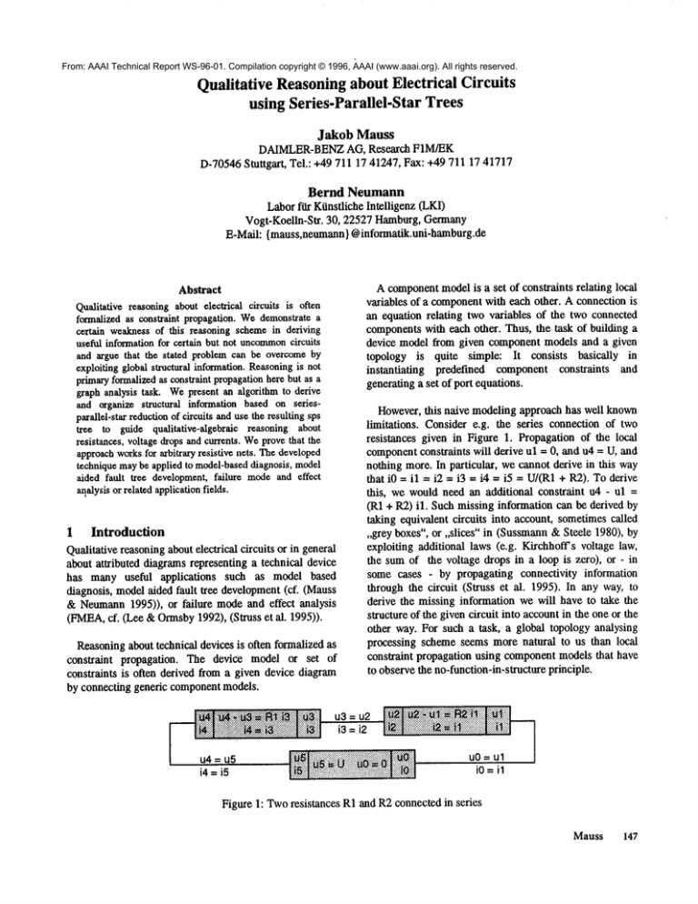
limitations. Considere.g. the series connectionof two
resistances given in Figure 1. Propagationof the local
component
constraints will derive ul = 0, and u4 = U, and
nothing more.In particular, wecannotderive in this way
that i0 = il = i2 = i3 = i4 = i5 = U/(R1+ R2). To derive
this, wewouldneed an additional constraint u4 - ul =
(R1 + R2) il. Suchmissinginformationcan be derived
taking equivalentcircuits into account, sometimescalled
,,grey boxes",or ,,slices" in (Sussmann
&Steele 1980),
exploiting additional laws (e.g. Kirchhoffsvoltage law,
the sumof the voltage drops in a loop is zero), or - in
somecases - by propagating connectivity information
throughthe circuit (Struss et al. 1995). In any way,
derive the missinginformationwewill haveto take the
structure of the givencircuit into accountin the oneor the
other way. For such a task, a global topologyanalysing
processing schemeseemsmorenatural to us than local
constraint propagationusing component
modelsthat have
to observethe no-function-in-structure
principle.
~......................
:~
........~:..
::: :. ::::::::::::::::::::::::::::::::::::::
:~:U~:.~::~:t=~
.:::::":::::...:::...::::;
~. u3=2 ..................
.:#.’.’.:::::
::::::::::::::::::::::::::::::::::::::::::::::::::::::::
::::::::: ......~.- ...
Iu4=.s lii
iliiiii
iiiiiiii!
iiili!ii
iiiiluo=
Figure1: Tworesistances R1and R2connectedin series
Mauss 147
In this paper we present a technique for qualitative
circuit analysis that generates the abovemissingstructural
constraints for arbitrary resistive nets. Our methodis a
qualitative one since we exploit the topology of a given net
and do not use any additional quantitative information.
2.1 Some Definitions
Let e = (v0, vl) be an edge. The edge e is called directed
fromv0 to vl, vO= start(e) is called the start nodeof e and
vl = end(e) is called the end node of e. Let nodeS(e)be
set { start(e) } w{ end(e)
In Section 2 we present an algorithm that reduces a
given resitive net to a single total resistance with respect
to a given source using series and parallel reduction and
star-mesh conversion. Weproof that the algorithm reduces
arbitrary networks. In Section 3 we demonstrate, howthe
trees resulting from net reduction can be used to derive
numeric, symbolic, or qualitative descriptions of the
resistances, voltage drops, and currents observable in the
given network.
Anedge e with start(e) = end(e) is called self-loop.
Twoedges e0 and el with nodes(e0) = nodes(el) and e0
not a self-loop are called parallel with each other.
2
SPS Reduction for Resistive
Nets
In this paper we assume that the device under
consideration can be represented as a resistive net. A
resistive net consists of resistances and an ideal voltage
source. Further we assume that all relevant assumptions
about faulty or operational states of the device’s
componentscan be translated to assignments of certain
values to the resistances and the source. For example,
"wire broken" might translate to "r = o,", and "switch
closed" to "r = 0" in the net. As illustrated in Figure 2, a
resistive net can be represented as a graph G = (13, V)
where V is a finite set of nodes and E ~ V×Vis a set of
directed edges labeled with the resistance or source it
represents. The direction of an edge e defines the sign of
the current through e and of the voltage drop across e.
An edge set E containing no self-loops and no parallel
edges is called edge reduced.
For every node v ~ V of a graph G = (E, V), edges(v)
the set of edges starting or ending at v, and degree(v)
the numberof edges contained in the edge set edges(v).
node v with degree(v) = 0 is called isolated.
Examples:In Figure 2, r6 and r7 are parallel edges, rl0
is a self-loop, edges(v3) = {r4, r5, rl0}, degree(v3)
and v8 is isolated.
2.2 Basic Operations on Graphs
Edge removal An edge e can be removed from the graph.
As a result, one or all of the nodes in nodes(e) may
becomeisolated.
Node removal A node v can be removed from the graph
by removingv and all the n = degree(v) edges starting
ending at v.
An edge can be removed from the graph by applying
one of the two edge removalrules:
SELF-LOOP An edge that
removedfrom the graph.
r7
r
rl 1
®
sO
®
_ r5
®
Figure 2: A resistive net represented as a directed graph
148
QR-96
can be
PARALLEL
If an edge e0 = (v0, vl) is parallel to
edge el then e0 and el can be replaced by an edge e with
e = (v0, vl) or e = (vl, v0), i.e. the direction of
replacing edge e can be chosen.
i9
\
is a self-loop
If a node v has a reduced edge set edges(v), can be
removed from the graph using one of the four node
removal rules depending on the number n = degree(v)
only:
ISOLATEDNODEn = 0. Remove v.
ENDBRANCH
n = 1. Because edges(v) = {e} is edge
reduced, e is not a self-loop. Removev. Following the
definition of node removal,this will also removee.
SERIESn = 2. Let edges(v) = {el, e2} with node(el)
{vl, v} and nodes e2 = {v2, v}. Because edges(v) is edge
reduced, vl and v2 are no self-loops, i.e. vl,v and v2~v,
and they are not parallel, i.e. vl~v2. Removev. This
removes also el and e2. Add a new edge e with
e = (vl, v2) or e = (v2, vl). Again, as for the PARALLEL
removalrule, the direction of e can be chosen.
STARn > 2. Let edges(v) = {el, e2 .....
en} with
nodes(ek) = {vk, v} for all k with < k < n. Because
edges(v) is edge reduced we have vk@v(no self-loops)
vj@vk(no parallel) for all j and all k with < j < k < n.
Remove v. This will also remove all the edges
e 1, e2 ..... en. Addn (n-1) / 2 directed edgesejk = (v j,
with 1 <j <k<n.
Figure 3 gives someexamplesof the star removal rule,
also knownas star-mesh conversion or generalized stardelta conversion.
reduoe-sps(E, V, s)
for each edge e e E, e ~ s
apply an edge removal rule
to e if possible
end for
for each node v ~ V, v ~ nodes(s)
remove v by applying the node
removal rule R(degree(v))
for each new edge e added
by the application of R
apply an edge removal
rule to e if possible
end for
end for
end reduoe-sps
Figure 4: The reduction algorithm
Theorem:Let G = (E, V) be an arbitrary not neccessary
connected graph that may contain isolated nodes, selfloops and parallel edges. Let s ¢ E be an edge, called the
source. Then the application of the procedure spsreduce(E, V, s) as given above will reduce G to a graph
= (E’, V’) with V’ = nodes(s)and E’ = {s} or E’ = {s,
r13
1"23
i2 = i12-i23
u2= r2 ( i12 - i23)
r12= rl r2 ((11rl)+(11r2)+(llr3))
Figure 3: Someinstances of the star removalrule and
details for the case n = 3.
2.3 An Algorithm for SPS Reduction
Weare nowready to present an algorithm that reduces any
graph G = (E, V) representing a resistive net to a single
edge e representing the total resistance of the net with
respect to a given source s ~ E. The reduction algorithm is
given in Figure 4. The abbreviation sps stands for seriesparallel-star because of the fact that every net can be
reduced using series, parallel, and star reduction. Westate
this important property of the algorithm in the following
theorem.
Proof: It is not hard to see that if a graphG = (E, V) has
reduced edge set E, i.e. contains no self-loops and
parallels, every node v e V can be removedfrom G using
one of the node removalrules, resulting in a smaller node
set V’ = V \ {v}. Hence, every node v ~ V \ nodes{s}
chosenin the for-each-node loop for removalcan infact be
removedby a node removalrule since the edge set E \ {s}
has been edge reduced in the initial for-each-edge loop and
remains edge reduced, since all edges added by a node
removalrule are checkedfor self-loops and parallels in the
for-each-new-edge loop. Edge removal cannot introduce
new nodes. Therefore, after the for-each-node loop, all
nodes except nodes(s) have been removed from
resulting in a reducednodeset V’ = nodes(s).
If the corresponding reduced edge set E’ wouldcontain
morethan two edges, say E’ = {s, el, e2}, el and e2 would
have to be self-loops or parallel, since V’ contains only one
or twonodes. This wouldcontradict the fact that E’ \ {s} is
edge-reduced. Hence, E’ can contain only one or two
edges, i.e. E’ = {s} or E’ = {s, e}.
To illustrate the reduction procedure, Figure 5 showsthe
reduction of the graph GOgiven in Figure 2 to a graph G6
containing only two edges sO and PA5.
Mauss
149
/"® r~®
®
so®~._~_~
®
®
E
1I°
®
G2
:.:.:.:.:+:.:.:,
...::i
PA5I
so
SE2
I sO
sO
sot,r’2O,,...
P
G6
G5
®
G4
G3
Figure 5: Sps reduction of a sample resistive network
The reduction algorithm does not define an ordering for
removing nodes ~omthe graph, any ordering is possible.
However, it turns out that always choosing a node with
minimal degree has some advantages: First, this strategy
leads often to shorter reduction sequences.
M~eover, if a graph can be reduced using seriesparallel reductions only the reduction algorithm will find
such a reduction when minimal-degree ordering is
applied. This avoids unneceessary star reductions.
Minimal-degree ordering can be implemented by
representing the node set V of a graph G = (E, V) as a list
of nodes, sorted by the degree of the nodes and always
choosingthe first node of the list for removal. Addingand
removingan edge will cause a reordering of that edge’s
start and end node.
3 Reasoning
using
SPS Trees
In the previous section we have presented an algorithm
that decomposesan arbitrary resistive net using series,
parallel and star-to-mesh reductions. In this section we
showhow the resulting sps trees - comparable to a tree
resulting from syntax analysis in natural language
processing - can be used to guide quantitative and
qualitative reasoning about the decomposednet.
150
QR-96
® ®
Figure 6: Sps trees resulting from the reduction given in
Figure 5
edge. Propagation of a request is done using the algebraic
relations given in Figure 7.
3.1 Deriving Symbolic or Numeric Values
Each removal of an edge or node during sps reduction is
represented by a non-leave node in the corresponding sps
tree as illustrated in Figure 6. The arrows in the tree
decode the sign of the currents and voltage drops.
Downarrow
represents a factor 1 and uparrowrepresents a
factor -1,We are interested in the currents and voltage
drops at the edges of the original unreducedgraph. These
edgesare representedby the leaves of the sps trees.
As one can see, the recursion for currents and voltages
proceeds in a bottom-up manner from the leave of asps
tree to its root, while the recursion for a resistance leads in
a top-downmanner from the root to the leaves. To
summarize,if we have generated the sps trees for a given
resistive
net, we can derive symbolic or numeric
expressions for all voltage drops and currents in the net by
recursively applying the algebraic relations in the table.
The sps tree dependson the topology of the net only, i.e.
has to be derived only once for a given net.
The basic idea is now to propagate any request for a
symbolic or numericexpression for a current or a voltage
drop at a leave of a sps tree upwardsto its root wherethe
answeris known,since the root is e.g. given by the source
END BRANCH
SELF-LOOP
SOURCE
®
u(e)
=
i(e)
=
u(e)
=
i(e)
=
SERIES
u(e)
= u(s)
i(e)
= u(s)
I
PARALLEL
STAR
ejk
©
©
el
1_<k~;2:
i(ek) = i(SE)
1<k~2:
i(ek) = u(PA)/ r(ek)
u(ek)= i(SE)r(ek)
u(ek)= u(PA)
r(SE)= r(el) + r(e2)
r(PA)
r(el) r(e2)
r(el) + r(e2)
1),qr(e2))
qr(SE)=Max(qr(el),qr(e2))qr(PA)=Min(qr(e
1 <k_<n:
k-1
n
i(ek) =~’. i(emk)~.i(ekm)
rn=l
m=k+l
u(ek)= i(ek) r(ek)
l<j<k~n:
n
r(ejk) = r(ej) r(ek)~..1
m=lr(em)
qr(ejk)= Min(qr(ej),qr(ek))
Figure 7: Graphreductions, correspondingsps trees and algebraic relations
Mauss
151
3.2 Deriving Qualitative Values
Often, we are interested only in qualitative descriptions.
For this purposewe define three sets of qualitative values,
ordered with respect to < as indicated below and
representing qualitative resistance and signed qualitative
current and voltage drop.
R = (
ZERO, POS, INF)
I = (MINF, NEG, ZERO, POS, INF)
U = (MMAX, NEG, ZERO, POS, MAX)
Voltage drops occuring in a resistive net are boundedto
a finite value MAXor minus MAX= MMAX,since we
are assuming an ideal voltage source. As a consequence,
the current through a ZERO
resistance might be infinite,
i.e. INFor MINF.Wecan nowinterprete the sps tree of a
circuit as a constraint net. Every node of the tree holds
three qualitative values qu, qr and qi. These values are
related with each other by qualitative abstractions of the
algebraic relations given in Figure 7. These abstractions
turn out to be surprisingly simple. For example, in starmeshconversion, the algebraic relation between rj, rk in
the star and rjk in the mesh,
n
rjk = rj rk ~ (1 / i)
i=l
simplifies in its qualitative version to
qrjk = Min(qrj, qrk)
where Min(ql,q2) is the minimumof the qualitative
values ql and q2 with respect to the qualitative < relation
defined above.
Wehave implemented sps reduction and constraint
propagationfor the resulting sps trees. Figure 8 showsthe
qualitative values for the currents derived by propagation
where all resistances of the unreduced resistive net were
initially set to POSand the voltage source was set to
MAX.Qualitative analysis cannot derive a unique value
for the current through the bridge resistor betweennodes
vl and v4, i.e. the current can be NEG,ZERO,or POS.
Only INF and MINFcould be defintely excluded by the
qualitative analysis. This is what we expect, since to
determine the current through the bridge, we have to take
the exact values of the resistances into account. However,
if this quantitative information is known,we can derive a
numericvalue for the missing bridge current from the sps
tree as describedin Section 3.1.
152
QR-96
®
=
U
MAX
®
ZERO
1 t’ZERO
®
Figure 8: Qualitative currents derived from the sps trees
4 Related
Work
In (Struss et al. 1995) the starting point is the sameas
this paper: The authors demonstrate the limitations of
local propagation with a three-resistance
circuit
concluding that global structural information should be
exploited. For that purpose they introduce the notion of
,,connectivity of a componentto sources and sinks of a
circuit". They develop a componentmodel that observes
the no-function-in-structure principle but is able - to a
certain degree - to derive the connectivity information for
a component by local propagation only. The local
connectivity information is used in turn to determine e.g.
the sign of the current through the component. However,
the methodworks only for circuits not containing certain
loops and not containing too manyseries connections.
(Lee & Ormsby1992) use series-parallel reduction
resistive nets in a waysimilar to the approach presented
here. However,their approachis limited to series-parallel
reducable networks, since they do not use star-mesh
conversion. As a consequence, they cannot cope with
resistive nets containing bridges, as for examplethe net
given in Figure 8.
Bond graphs (cf. (Karnopp, Margolis, & Rosenberg
1990)) provide an elegant framework for representing
dynamicalsystems. It turns out that a circuit’s sps tree as
used in this paper is isomorphto the circuit’s bondgraph
if the circuit is series-parallel reducable, i.e. is reducable
without star-mesh
conversion.
Otherwise the
corresponding bond graph contains a loop, i.e. is not a
tree.
(Chen 1976) presents an elaborated theory about the
relations between graphs and linear systems representing
e.g. general RLC-networks.These relations might proof to
be useful for qualitative reasoning. However,it is still an
open question - at least to the authors - howthis work
relates to the sps approachfor resistive networkspresented
here.
5
Conclusion
We developed a method for reasoning about analog
circuits or other devices whose behaviour can be modeled
by resistive networks. The given networkis first reducedto
a total resistance using series- and parallel reduction, and
star-to-mesh conversion. Weproved that these three rules
suffice to reduce arbitrary networks. Weshowedhow the
resulting sps tree (actually a dag - a directed acyclic graph)
can be used to derive numeric, symbolic and qualitative
values for the quantities occuringin the net.
Reasoning is not exclusively viewed as constraint
propagation here but as a graph analysis task too. This
enables us to exploit global structural information in a way
that would be hard to achieve with traditional local
propagation techniques only, i.e. without explicit graph
analysis.
References
Chen, W. K. 1976. Applied Graph Theory: Graphs and
Electrical Networks. North-HollandPublishing, Second
RevisedEdition.
Karnopp,D. C., Margolis, D. L., Rosenberg,R. C. 1990.
System Dynamics:A Unified Approach. Second Edition,
John Wiley & Sons.
Lee, M. H., Ormsby,A. R. T. 1992. Qualitative Modeling
of Electrical Circuits, In QR’92:Sixth International Workshop on Qualitative Reasoningabout Physical Systems,
Heriot-Watt University, Edinburgh,Scotland, 155-169.
MaussJ., Neumann,B. 1995. Diagnosis by Algebraic
Modelingand Fault-Tree Induction. In DX-95:Sixth
International Workshop
on Principles of Diagnosis, Goslar,
Germany,73-80.
Struss, P., Malik, A., Sachenbacher,M. 1995. Qualitative
Modelingis the Key. In DX-95:Sixth International Workshop on Principles of Diagnosis, 99-106.
Sussmann, G. J., Steele, G. L. 1980. CONSTRAINTS
- A
Languagefor Expressing Almost-Hierarchical
Descriptions,Artificial Intelligence 14, 1-39.
Mauss
153

