Technical Data
Effective October 1, 2014
UIG-2-NA – Universal Interface
Catalog#
Prepared by
Project
Date
Comments
Type
Overview
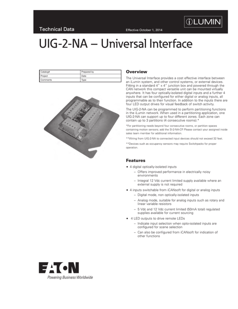
The Universal Interface provides a cost effective interface between
an iLumin system, and other control systems, or external devices.
Fitting in a standard 4” x 4” junction box and powered through the
CAN network this compact versatile unit can be mounted virtually
anywhere. It has four optically-isolated digital inputs and a further 4
inputs that can be configured for either digital or analog inputs, all
programmable as to their function. In addition to the inputs there are
four LED output drives for visual feedback of switch activity.
The UIG-2-NA can be programmed to perform partitioning functions
in the iLumin network. When used in a partitioning application, one
UIG-2-NA can support up to four different zones. Each zone can
contain up to 3 partitions (4 consecutive rooms).*
*For partitioning needs beyond four consecutive rooms, or partition spaces
containing motion sensors; add the SI-2-NA-CP. Please contact your assigned inside
sales team member for additional information.
**Wiring from UIG-2-NA to connected input devices should not exceed 32 feet.
**Devices such as occupancy sensors may require Switchpacks for proper
operation.
Features
4 digital optically-isolated inputs
−− Offers improved performance in electrically noisy
environments
−− Integral 12 Vdc current limited supply available where an
external supply is not required
4 inputs switchable from iCANsoft for digital or analog inputs
−− Digital mode, non optically-isolated inputs
−− Analog mode, suitable for analog inputs such as rotary and
linear variable resistors
−− 5 Vdc and 12 Vdc current limited (50mA total) regulated
supplies available for current sourcing
4 LED outputs to drive remote LEDs
−− Indicate input selection when opto-isolated inputs are
configured for scene selection
−− Can also be configured from iCANsoft for indication of
other functions
Technical Data
UIG-2-NA – Universal Interface
October 2014
Specifications
Electrical Data
Mechanical Data
(Inches/mm)
4.33 in (110 mm)
.66 in
(16.73mm)
3.19 in (81.14 mm)
Wiring Diagram
www.coopercontrol.com
4.33 in(110 mm)
Standards
2
.66 in (16.73mm)
3.19 in (81.14 mm)
Environmental Data
Supply: 12 Vdc via the iCANnet network
iCANnet connection: Screw terminals within
two part connectors, able to accept 16 AWG
(1.5mm2) stranded or solid wire.
Inputs: Screw terminals within two part
connectors, able to accept 16 AWG (1.5mm2)
stranded or solid wire.
LED outputs: Screw terminals within two part
connectors, able to accept 16 AWG (1.5mm2)
stranded or solid wire.
Mounting: fits a standard 4” x 4” junction box
(not provided)
Temperature Range:
32°F to 104°F (0°C - 40°C)
Humidity: 0% - 95% non-condensing
Dimensions
1.20 in.
(30.60 mm)
Technical Data
UIG-2-NA – Universal Interface
October 2014
Sample System Topology
SC277-12-UN-3P-ML-20
DRY CONTACT
CLOSURE
TUNGSTEN
SC277-24-UN-3P-ML-20
DMX OUTPUT CONSOLE
BY ZERO 88 OR OTHERS
DMX512
DISCHARGE
TUNGSTEN
2, 3 & 4 WIRE
FLUORESCENT
SECURITY OCCUPANCY
SENSOR
SYSTEM
AV
COMPONENTS
DISCHARGE
COLD CATHODE
COLOR CHANGING
FIXTURES
DRY CONTACT
CLOSURE
CONTACT
CLOSURE
INPUT
2, 3 & 4 WIRE
FLUORESCENT
COLD CATHODE
COLOR CHANGING
FIXTURES
CLS-4TSB-RL-W-IR
Scene 1
Scene 2
Scene 3
CLS-3TLB-W-IR
UIG-2-NA
RS232
Scene 4
SI-2-NA
CLS-1TLB-W
Scene 1
Scene 1
Scene 2
Scene 3
HH17IR
iCANnet
Cable type - Cooper LC Cable or Belden™ 1502R (NON PLENUM) or 1502P (PLENUM)
Maximum segment distance of 1000m/3200ft per segment
Ordering
Model
Description
UIG-2-NA
Universal Interface
Eaton
1000 Eaton Boulevard
Cleveland, OH 44122
United States
Eaton.com
Eaton’s Cooper Controls Business
203 Cooper Circle
Peachtree City, GA 30269
coopercontrol.com
© 2014 Eaton
All Rights Reserved
Printed in USA
Publication No. ACC140933
October 1, 2014
Eaton is a registered trademark.
All other trademarks are property
of their respective owners.


