Fusing Equipment
Catalog Data
CA132059EN
Effective February 2016
Supersedes 240-64A August 1995
COOPER POWER
SERIES
K-Limiter high ampere Companion II
fuse
General
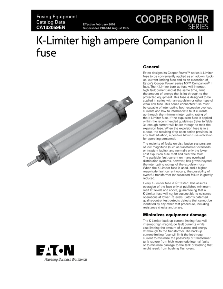
Eaton designs its Cooper Power™ series K-Limiter
fuse to be conveniently applied as an add-on, backup, current-limiting fuse and as an extension of
Eaton's Cooper Power series NX™ Companion® II
fuse. The K-Limiter back-up fuse will interrupt
high fault current and at the same time, limit
the amount of energy that is let-through to the
protected equipment. This fuse is designed to be
applied in series with an expulsion or other type of
weak link fuse. This series connected fuse must
be capable of interrupting both excessive overload
currents and low to intermediate fault currents
up through the minimum interrupting rating of
the K-Limiter fuse. If the expulsion fuse is applied
within the recommended guidelines (refer to Table
3), enough current will be let-through to melt the
expulsion fuse. When the expulsion fuse is in a
cutout, the resulting drop open action provides, in
any fault situation, a positive blown fuse indication
for operating personnel.
The majority of faults on distribution systems are
of low magnitude (such as transformer overloads
or incipient faults), and normally only the lower
cost expulsion fuse melt and clear the fault.
The available fault current on many overhead
distribution systems, however, has grown beyond
the interrupting ratings of the expulsion fuse.
When the K-Limiter fuse is used, and a higher
magnitude fault current occurs, the possibility of
eventful transformer (or capacitor) failure is greatly
reduced.
Every K-Limiter fuse is I2t tested. This assures
operation of the fuse only at published minimum
melt I2t levels and above, guaranteeing that a
K-Limiter fuse will not be susceptible to nuisance
operations at lower I2t levels. Eaton's patented
quality-control test detects defects that cannot be
identified by any other test procedure, including
resistance checks and x-rays.
Minimizes equipment damage
The K-Limiter back-up current-limiting fuse will
interrupt high magnitude fault currents while
also limiting the amount of current and energy
let-through to the transformer. The back-up
current-limiting fuse will limit the let-through
current to minimize the possibility of transformer
tank rupture from high magnitude internal faults
or to minimize damage to the tank or bushing that
might result from bushing flashovers.
Catalog Data CA132059EN
K-Limiter high ampere Companion II fuse
Effective February 2016
Enhanced power quality and improved
service continuity
The operation of the K-Limiter back-up current-limiting fuse will
enhance power quality of the system and improve service continuity
during high magnitude faults. The duration of the voltage dip associated with system short circuits will be limited to the short melt time
of the K-Limiter fuse. Immediately after melting, the arc voltage
generated by the current-limiting fuse will support system voltage
until the fault is interrupted by the fuse. For high fault currents, the
duration of the voltage dip associated with the melt time of the
K-Limiter fuse will be well within the allowable limits for sensitive
electronic equipment as defined by CBEMA curves.
Production tests
Tests are conducted in accordance with Eaton requirements.
•
100% Physical Inspection
•
100% I2t Testing
•
100% Resistance Testing
Table 1. Electrical Ratings and Characteristics
Fuse Type
Back-up
Voltage and Current Ratings
4.3 kV
50-80 K
8.3 kV
65-140 K
15.5 kV
65-80 K
Maximum Interrupting
Current
50,000 A rms symmetrical
Table 3. K-Limiter Fuse Voltage Application
System Voltage (kV)
Nominal
Recommended
K-Limiter Rating (kV)
Maximum
Four Wire
Multi-grounded
Neutral
Delta
2.4
2.4/4.16
4.16
4.8
4.8/8.32
6.9
6.93/12.0
7.2
7.2/12.47
7.62
7.62/13.2
7.97
7.97/13.8
8.32
8.32/14.4
12/20.8
12.47
13.2/22.9
13.2
13.8
14.4/24.9
14.4
2.54
2.54/4.4
4.4
5.1
5.1/8.8
7.26
7.3/12.7
7.62
7.62/13.2
8.1
8.1/14.0
8.4
8.4/14.5
8.8
8.8/15.2
12.7/22.0
13.2*
14/24.2
14*
14.5*
15 2/26.4
15.2*
–
4.3
–
–
8.3
–
8.3
–
8.3
–
8.3
–
8.3
–
8.3
15.5
–
15.5
–
–
15.5
–
4.3
–
4.3
8.3
–
8.3
–
8.3
–
8.3
–
8.3
–
8.3
–
–
8.3**
–
8.3**
8.3**
–
8.3**
* Fuse voltage ratings recommended for these systems are based on simultaneous operation of the
K-Limiter fuses for high current faults.
**For single phase applications on delta systems, one fuse of this rating is required in each phase.
Table 2. Protective Characteristics
Voltage
Rating (kV)
4.3
8.3
15.5
K-Limiter
Rating*
Maximum
Continuous
Current
Minimum
Melt I2t
(A2s)**
Maximum
Let-through
I2t
(A2s)
Table 4. K-Limiter Fuse-Fuse Link Coordination
50
80
65
80
100
140
65
80
100 A
110 A
100 A
110 A
130 A
150 A
100 A
110 A
9000
26,000
24,460
46,900
100,000
100,000
24,460
46,900
265,000
400,000
240,000
294,000
360,000
700,000
240,000
295,000
K-Limiter
Fuse Rating
ANSI
Type K
ANSI
Type T
M.E.
Type N
50 K
65 K
80 K
100 K
140 K
50
65
80
100
140
30
30
40
50
80
60
60
75
75
85
Kearney
Type QA
Kearney
Type KS
60
75
75
100
150
20
25
30
30
50
* Coordinates with NEMA® Type K fuse links up through designated rating (amperes). Contact your
Eaton representative for coordination assistance with other types of expulsion fuse links.
**Minimum melt I2t is for the back-up current-limiting fuse section only.
2
www.eaton.com/cooperpowerseries
Coordinates With Fuse Links Up Through
50 K
65 K
80 K
100 K
140 K
Catalog Data CA132059EN
K-Limiter high ampere Companion II fuse
Effective February 2016
K-LIMITER
FUSE
ARRESTER
CUTOUT FUSE
LINK IN FUSEHOLDER
ARRESTER
CUTOUT FUSE
LINK IN FUSEHOLDER
TRANSFORMER
PRIMARY
BUSHING
TRANSFORMER
PRIMARY
BUSHING
Figure 3. Load-side cutout installation.
Figure 5. Hot-line/bail installation.
K-LIMITER
FUSE
TRANSFORMER
PRIMARY BUSHING
ARRESTER
K-LIMITER
FUSE
K-LIMITER
FUSE
CUTOUT FUSE
LINK IN FUSEHOLDER
K-LIMITER
FUSE
TRANSFORMER
PRIMARY
BUSHING
Figure 1. Source-side cutout installation.
ARRESTER
K-LIMITER FUSE
TRANSFORMER
PRIMARY
BUSHING
CUTOUT FUSE
LINK IN FUSEHOLDER
TRANSFORMER/CAPACITOR
PRIMARY
BUSHING
Figure 2. Bushing mount installation.
Terminal options
The K-Limiter fuse is avail­able with several
types of terminal options. Any combination
of spline stud, parallel-groove, spade or
eyebolt connector is available.
ARRESTER
DIRECT
CONNECT
ARRESTER
HIGH ENERGY
SECONDARY ARRESTER
Figure 4. CSP transformer installation.
0.44" (11.2 mm)
ROUND HOLE
FUSE CUTOUT
WITH DUAL
ELEMENT FUSE
(X OR D LINK
ALUMINUM
PARALLEL
GROOVE
CONNECTOR
#8-2/0 ALUM.
OR CU.
CONDUCTOR
Figure 6. Lightning-Protected transformer
(LPT) installation.
0.44" (11.2 mm)
ROUND HOLE
1.25"
(31.8 mm)
1.25"
(31.8 mm)
1.57"
(40 mm)
Figure 8. Spade with Parallel Groove connector terminal.
Figure 10. Spade terminal.
1.15"
(29.2 mm)
2.5"
(63 mm)
Figure 7. Eyebolt terminal (#8 through
2/0).
Figure 9. Spline stud terminal.
1/2-13 UNC
2B THREAD
Figure 11. End boss terminal.
www.eaton.com/cooperpowerseries
3
Catalog Data CA132059EN
Effective February 2016
Application
Voltage selection
The K-Limiter fuse has voltage ratings compatible with most
common distribution voltages.
Table 2 lists the most common distribution voltages, connec­tions
and the corresponding K-Limiter fuse voltage rating. For voltage
ratings or connections other than those listed, consult your Eaton
representative.
Current coordination
A 65 K K-Limiter fuse will coordinate with ANSI® Type K fuse links
rated 65 A or less. The 80 K K-Limiter fuse will coordinate with
ANSI® Type K fuse links rated 80 A or less, the 100 K K-Limiter fuse
will coordinate with ANSI® Type K fuse links 100 A or less, and the
140 K K-Limiter fuse will coordinate with ANSI® Type K fuse links
140 A or less. Distribution systems using expulsion fuses other
than ANSI® Type K fuse links can also be coordinated with K-Limiter
fuses (Table 3). Contact your local Eaton representative for any
further assis­tance.
Arc voltage considerations
A K-Limiter fuse, when applied correctly, generates arc voltages
well below arrester sparkover levels. The protective characteristics in
Table 4 are the maximum peak-arc voltages for each K-Limiter fuse
at rated voltage. Peak arc voltages will be lower when the fuses are
used at system voltages lower than the fuse’s rated voltage.
Installation
A K-Limiter fuse can be added to new or existing distribution
equipment installations to provide the energy l­imiting protection that
is needed. The fuse can be mounted in open or enclosed cutout
terminals as well as transformer bushing terminals. It can also be
suspended in the drop leads or used with hot-line connectors. When
installing a K-Limiter fuse, observe the following guidelines:
1. Arrester can be connected on either the source or load side.
1. Direct expulsion gases from cutouts away from any K-Limiter
fuse mounted nearby as well as away from adjacent equip­ment.
1. Maintain normal system phase and ground spacings.
Installation examples are shown in Figures 2 through 6.
4
www.eaton.com/cooperpowerseries
K-Limiter high ampere Companion II fuse
Catalog Data CA132059EN
K-Limiter high ampere Companion II fuse
Effective February 2016
Dimensions and weights
2.50"
2.50"
(63.5
mm)
(63.5 mm)
3.12"
(79.2
mm)
3.12"
(79.2
.81"
.81"
(20.6 mm)
1.88" (20.6
mm)
(47.7 mm) 1.25"
1.25"
(31.7 mm)
(31.7
mm)
“A”
“A”
mm)
.44" (11.2 MM) DIA.
HOLE
KNURLED
SPLINE STUD
.44" (11.2 mm) DIA. HOLE
.63"
.63"
(16.0 mm)
(16.0
mm)
STANDARD DESIGN
FUSE TUBE
STANDARD
DESIGN
FUSEUTILIZES
TUBE
GRAY EPOXY PAINTED SURFACE
UTILIZES GRAY EPOXY PAINTED
SURFACE
Figure 12. K-Limiter back-up current-limiting fuse dimensional Information (Refer to Table 3).
Table 5. Dimensional Information
Voltage Rating
4.3 kV
Fuse Ampere
Rating
K50
K80
A in. (mm)
Approx. Weight
lbs (kg)
6.42
(163.1)
3
(1.4)
11.94
(295.6)
5.5
(2.5)
16
(406)
9
(4.0)
K65
8.3 kV
K80
K100
K140
15 kV
K65
K80
www.eaton.com/cooperpowerseries
5
Catalog Data CA132059EN
K-Limiter high ampere Companion II fuse
Effective February 2016
Ordering information
Table 7. 4.3 kV K-Limiter Fuse
Selecting a catalog number
To order a K-Limiter fuse, first choose a fuse voltage and current
rating from the Application Section on page 2. After selecting the
fuse size choose the appropriate Base Catalog Number from Tables
7, 8 or 9 and add the appropriate terminal option code from Table 6.
Current
Rating
Interrupting
Rating
(kA-Sym)
50K
80K
K-Limiter Fuse Catalog Number
Base
Catalog Number
Terminal Code
50
43K050
Refer to Table 7
50
43K080
Refer to Table 7
Table 6. Terminal Options*
Terminal
Code
Description
“-A1”
Spade and Eyebolt Connector
“-B1”
Table 8. 8.3 kV K-Limiter Fuse
Spline Stud and Spade Connector
Current
Rating
Interrupting
Rating
(kA-Sym)
“-B2”
Spline Stud and Spade with Parallel-Groove Connector
50K
“-C1”
Spade and Spade
K-Limiter Fuse Catalog Number
Base
Catalog Number
Terminal Code
50
83K050
Refer to Table 7
65K
50
83K065
Refer to Table 7
Spade and Spade w/Parallel-Groove Connector
80K
50
83K080
Refer to Table 7
“-D1”
End Boss and Spade
100K
50
83K100
Refer to Table 7
“-D2”
End Boss and Spade w/Parallel-Groove Connector
140K
50
83K140
Refer to Table 7
“-D3”
End Boss and Eyebolt
"-E1"
Spline Stud and Eyebolt
“-C2”
6
www.eaton.com/cooperpowerseries
Table 9. 15.5 kV K-Limiter Fuse
Current
Rating
Interrupting
Rating
(kA-Sym)
50K
65K
80K
K-Limiter Fuse Catalog Number
Base
Catalog Number
Terminal Code
50
155K050
Refer to Table 7
50
155K065
Refer to Table 7
50
155K080
Refer to Table 7
K-Limiter high ampere Companion II fuse
Catalog Data CA132059EN
Effective February 2016
Additional information
Refer to the following reference literature for additional information:
MN132001EN K-Limiter Back-up Current-Limiting Fuse Installation Instructions
www.eaton.com/cooperpowerseries
7
Catalog Data CA132059EN
K-Limiter high ampere Companion II fuse
Effective February 2016
Eaton
1000 Eaton Boulevard
Cleveland, OH 44122
United States
Eaton.com
Eaton’s Cooper Power Systems Division
2300 Badger Drive
Waukesha, WI 53188
United States
Eaton.com/cooperpowerseries
© 2016 Eaton
All Rights Reserved
Printed in USA
Publication No. CA132059EN
Eaton is a registered trademark.
All other trademarks are property
of their respective owners.
For Eaton's Cooper Power series product
information call 1-877-277-4636 or visit:
www.eaton.com/cooperpowerseries.

