Fusing Equipment
Catalog Data
CA132048EN
Effective December 2015
Supersedes 240-62 January 1990
COOPER POWER
SERIES
NX® current-limiting fault guard tool
General
Eaton's Cooper Power™ series NX® fault guard
tool can be applied anywhere that it is desirable
to provide temporary current limitation when
energizing a load. One application is to connect
an overhead transformer through the NX fault
guard tool to the line. If a fault is present, the
non-expulsion, current-limiting fuse in the tool will
operate harmlessly and limit the energy that gets
through to protected equipment.
Other applications include minimizing the
expulsion blast on any fuse cutout application,
limiting catastrophic transformer failures, hot-line
testing for a shorted surge arrester.
In performing these functions, the tool utilizes a
fuse unit borrowed from the NXD line of outdoor,
current-limiting fuses.
The fault guard tool with the self-extracting
electrical cable is for use with distribution
transformers protected by open-fuse cutouts.
The complete tool consists of the fuse unit (sold
separately), an upper end fitting for clamping the
tool to the line, a lower end fitting for retaining
the indicating squib parts during operation, a
self-retracting electrical cable extendable up to 10
feet for flexibility, and a pigtail-shaped switchstick
head. The switchstick is for lifting the tool, making
contact with the pull ring and closing the cutout.
The companion model, equipped with a metal
stirrup, is for use with self-protected transformers.
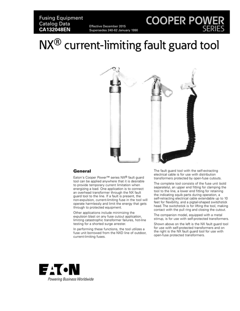
Shown above on the left is the NX fault guard tool
for use with self-protected transformers and on
the right is the NX fault guard tool for use with
open-fuse protected transformers.
Catalog Data CA132048EN
NX current-limiting Fault Guard tool
Effective December 2015
Features and detailed description
The fault guard tool, catalog number FA21M1, is intended for use
with self-protected transformers. An aluminum rod (stirrup) attached
to the lower-end fitting equips the tool to accept the hot-line clamp
on a transformer bushing lead. "Fuzzing" at the clamp/rod connection
and non-operation of the tool's fuse indicate that no fault is present
and the circuit may be safely energized. In the event of a fault,
operation of the fuse is reported by a loud "pop" from the squibactuator. Squib operation can also be verified visually. After repair of
the fault and replacement of the tool's fuse, which can be done in
seconds with an ordinary screwdriver, the circuit can be retested.
The other fault guard tool model, catalog number FA18M1, is
designed for use with distribution transformers protected by
open-fuse cutouts. Like its companion tool, the complete device
consists of an NXD fuse unit (sold separately) an upper-end fitting
for clamping the tool to the line, a lower-end fitting for retaining the
indicating squib parts during operation. In place of the aluminum
stirrup, this tool has a self-retracting electrical cable, extendable
up to ten (10) feet, and a pigtail-shaped switchstick head for lifting,
making contact with the cutout pullring and closing the cutout.
"Fuzzing" at the pigtail/pullring and nonoperation of the tool's fuse
indicate that the cutout can be safely closed.
Correctly applied, the NX fault guard tool will limit the energy
available to a faulted load to a level that will prevent double-vented
cutouts from blowing the expendable caps Experiments indicate
that the maximum probable duty levels shown in the coordination
tables are within this limit. It is recommended that the tool be used
only with cutouts having ungrounded-hangers. Where hangers are
grounded, the tool should be used only with cutouts having springloaded leader ejectors.
Tables 1 and 2 show recommended fuses for use in the NX fault
guard tool for single-phase applications. These recommendations
are based on information taken from Reference Data, R240-30-1 (for
delta connected primaries, 200-300 percent protection, EEI-NEMA
K or T links). Duty levels specified in these tables are the maximum
levels likely to occur. The probability of occurrence of theoretically
possible higher levels is considered to be less than one percent.
The operation of the NX fault guard tool in combination with an
expulsion fuse cutout will occur in one of three modes:
1. Exuplsion fuse operates, tool fuse does not
2. Expulsion fuse does not operate, tool fuse does
3. Both fuses operate
Mode 1 will occur in the case of low faults where the minimum
melt of the expulsion fuse is less than the minimum melt of the NX
fuse. Mode 2 will occur in the case of high faults of a level that the
let-through I2t is less than the minimum melt I2t of the expulsion
fuse. Mode 3 will occur in the case of high faults of a level that the
let-through I2t is greater than the minimum melt I2t of the expulsion
fuse, or low current faults where both fuses melt at approximately
the same time. Non-operation of either fuse indicates that no fault is
present. An open circuit in the load or an open fuse can be detected
by fuzzing the switchstick head along the cutout pullring. If the
circuit is open, no fuzzing will be detectable.
Table 1. Fusing Schedule for NX Fault Guard Tool at 14.4 kV (With 15.5 kV NXD Fuse Unit)
Scheme 1
Scheme 2
Sized for Minimum No. of Fuse Sizes
K Link
Sized for Minimum Expulsion Duty
T Link
K Link
T Link
Link Size
K or T
Min. Tool
Fuse
Size*
15.5 kV
Tool Fuse
Size
Max.
Expect
Duty
Max. Low
I Duty
Max.
Expect
Duty
Tool Low
I Duty
15.5 kV
Max.
Fuse Size
Max.
Expect
Duty
Max;.
Low I
Duty
Max.
Expect
Duty
Max. Low
I Duty
500
40
40
40C
496
490
–
300
40C
496
490
–
300
333
30
30
40C
1410
610
–
370
30C
–
350
–
230
300
25
30
40C
1745
800
–
450
30C
1210
410
–
280
250
20
20
20C
595
170
–
120
20C
595
170
–
120
200
15
18
20C
844
210
–
140
20C
844
210
–
140
167
12
18
20C
1040
300
187
155
20C
1040
300
187
155
150
12
18
20C
1040
300
187
155
20C
1040
300
187
155
100
8
10
20C
1160
450
1035
270
10C
666
45
420
38
75
6
10
20C
1188
450
1120
450
10C
720
230
600
35
50
6
6
20C
1188
450
1120
450
10C
720
230
600
35
37.5
6
6
20C
1188
450
1120
450
10C
720
230
600
35
25
6
6
20C
1188
450
1120
450
10C
720
230
600
35
15
6
6
20C
1188
450
1120
450
10C
720
230
600
35
10
6
6
20C
1188
450
1120
450
10C
720
230
600
35
5
6
6
20C
1188
450
1120
450
10C
720
230
600
35
3
1H
6
20C
1220
450
1220
450
10C
768
230
768
230
Transformer
kVA
667
* Minimum size for the tool fuse (C-rated) is based on the multiple of 25 times inrush current.
2
www.eaton.com/cooperpowerseries
Catalog Data CA132048EN
NX current-limiting Fault Guard tool
Effective December 2015
Table 2. Fusing Schedule for NX Fault Guard Tool at 19.9 kV (With 23 kV NXD Fuse Unit)
Scheme 1
Scheme 2
Sized for Minimum No. of Fuse Sizes
Sized for Minimum Expulsion Duty
K Link
T Link
23 kV
Tool Fuse
Size
Max.
Expect
Duty
Max. Low
I Duty
Max.
Expect
Duty
K Link
T Link
Transformer
kVA
Link Size
K or T
Min. Tool
Fuse
Size*
Tool Low
I Duty
23 kV
Max.
Fuse Size
Max.
Expect
Duty
Max;.
Low I
Duty
Max.
Expect
Duty
Max. Low
I Duty
667
40
40
40C
406
480
-
320
40C
406
480
-
320
500
30
30
40C
1380
600
-
380
30C
-
340
–
240
333
20
20
20C
540
170
-
120
20C
540
170
-
120
300
20
18
20C
540
170
-
120
20C
540
170
-
120
250
15
18
20C
806
210
-
140
20C
807
210
-
140
200
12
12
20C
1010
255
-
160
12C
814
55
-
50
167
10
12
20C
1086
460
858
200
12C
908
85
615
53
150
8
12
20C
1128
460
1005
260
12C
960
350
807
60
100
6
10
20C
1160
460
1090
450
12C
996
350
915
95
75
8
10
20C
1160
460
1090
450
12C
996
350
915
95
50
8
10
20C
1160
460
1090
450
12C
996
350
915
95
37.5
8
10
20C
1160
460
1090
450
12C
996
350
915
95
25
8
10
20C
1160
460
1090
450
12C
996
350
915
95
15
8
10
20C
1160
460
1090
450
12C
996
350
915
95
10
8
10
20C
1160
460
1090
450
12C
996
350
915
95
5
8
10
20C
1160
460
1090
450
12C
996
350
915
95
3
1H
10
20C
1194
460
1194
450
12C
1035
360
1035
360
* Minimum size for the tool fuse (C-rated) is based on the multiple of 25 times inrush current.
Interpreting the tables
The interpretation of Tables 1 and 2 can best be explained by
example. With a 100 kVA transformer fused by an eight amp K- or
T-rated link on a 15.5 kV system, the minimum fuse size that should
be used in the NX fault guard tool is ten (10) amps (Table 1). This
size will assure that transformer inrush current will not cause fuse
operation. Satisfactory operation of the tool, however, can be
achieved by using a fuse rated as high as 20 amps. For Scheme 1
(mimimum number of fuse sized required), the 20C fuse used in
this example will allow a maximum expected expulsion duty of 1160
amps on a mode 3 operation, and a maximum low current duty of
450 amps on a mode 1 operation where the cutout is fused with an
eight-amp K-rated link. The maximum high and low fault duties for
T-rated links are also listed. Scheme 2 is offered with fuses selected
so that minimum expulsion duty is allowed. This portion of the table
can be interpreted similar to Scheme 1. Dashes in the tables indicate
that duty of the expulsion fuse is not expected.
it is important to note that the duties specified in the tables are
expected-worst-case duties. These levels re well within the design
goal.
The following information will aid in determining proper fuse
sizes for use in the NX fault guard tool where transformer fuse
combinations other than those covered in Tables 1 and 2 are used.
The selected fuse must lie within a range defined by a minimum
rating determined by transformer inrush current, a maximum rating,
determined by comparing maximum expected let-through of the tool
fuse to average melt of the expulsion fuse. Minimum size to prevent
fuse damage from transformer inrush current can be selected from
the tables.
duty of no more than 1800 amps. Calculate maximum expected
expulsion duty using the following procedure.
Step 1
Look up the following values
1. Minimum melt I2t of the NX fuse, NXmin. This value can be
found in the appropriate bar graph of Reference Data R240-60-5.
2. Maximum total I2t of the NX fuse, NXmax. This value can also be
found on the respective gar graph of Reference Data R240-60-5.
3. Minimum melt current for link at 0.01 second, lL. This value can
be found from the minimum melt TCC curves published by the
manufacturer of the link.
Step 2
Calculate the following values
1. Average melt I2t for the link, PL; PL = (1.1 IL)2 X 0.01
2. (Arcing I2t)1 for NX fuse, A1: A1 = (0.85 NXmax - 1.1 NXmin)
3. (Arcing I2t)2 for NX fuse, A2;
[[
A2 = A1 VS 2
VR
where:
VS = system voltage
VR = rated voltage of fuse cartridge
Maximum fuse size should be selected so that the combinations of
NX fuse and expulsion fuse result in a maximum expected expulsion
www.eaton.com/cooperpowerseries
3
Catalog Data CA132048EN
NX current-limiting Fault Guard tool
Effective December 2015
Step 3
Calculate max expected let-through I2t, X
X = A2 + 1.1 NXmin
Step 4
Voltage Rating
(kV)
Convert X to half-wave current
√
X-PL
0.00833
Table 3. NX Fault Guard Tool Fuse Replacement Units
(Current-Limiting, Outdoor, Interrupting Capacity 50,000 Amps
Symmetrical)
= Max expected
expulsion duty in amps rms
Where the maximum let-through I2t of the NX fuse is less than the
minimum melt I2t of the link, operation of the link will be prevented.
Where some duty of the link is considered acceptable, maximum
let-through of the NX fuse can be slightly higher (no more than 1800
amps) than the minimum melt I2t of the link. Once the maximum
and minimum fuse sizes have been selected, the fuse unit of the
appropriate size can be selected from Table 3.
15.5
For efficient field operation, it is recommended that a schedule
relating transformer kVA and NX fault guard tool fuse rating be
prepared which considers the particular fusing practices of the using
organization.
Information on the manner in which current is limited by the NX
fuse is published in Catalog Data CA132049EN NX Indoor CurrentLimiting Fuse.
23
Dimensions
Continuous Current
(Amps)
Replacement Catalog
Number*
6
FAG4A6R
8
FAG4A8R
10
FAG4A10R
12
FAG4A12R
18
FAG4A18R
20
FAG4A20R
25
FAG4A25R
30
FAG4A30R
40
FAG4A40R
6
FAG5A6R
8
FAG5A8R
10
FAG5A10R
12
FAG5A12R
18
FAG5A18R
20
FAG5A20R
25
FAG5A25R
30
FAG5A30R
40
FAG5A40R
A
Dimension
(in.)
17-3/8
20-1/4
Ordering information
The NX fault guard tool accepts 15.5 and 23 kV NX
fuse replacement units with current ratings from 6
to 40 amps. Fuse units for use with the tool are sold
separately and can be selected from Table 3.
Fault Guard Tool
Catalog Number
With metal stirrup
FA21M1
With electrical cable
FA19M1
Figure 1. NX Fault Guard FA21M1 and FA18M1.
Eaton
1000 Eaton Boulevard
Cleveland, OH 44122
United States
Eaton.com
Eaton’s Cooper Power Systems Division
2300 Badger Drive
Waukesha, WI 53188
United States
Eaton.com/cooperpowerseries
© 2015 Eaton
All Rights Reserved
Printed in USA
Publication No. CA132048EN
Eaton is a registered trademark.
All other trademarks are property
of their respective owners.
For Eaton's Cooper Power series product
information call 1-877-277-4636 or visit:
www.eaton.com/cooperpowerseries.


