Deadbreak Connectors
Catalog Data
CA650052EN
Effective October 2015
Supersedes May 2015
COOPER POWER
SERIES
600 A 35 kV class PUSH-OP®
deadbreak connector
General
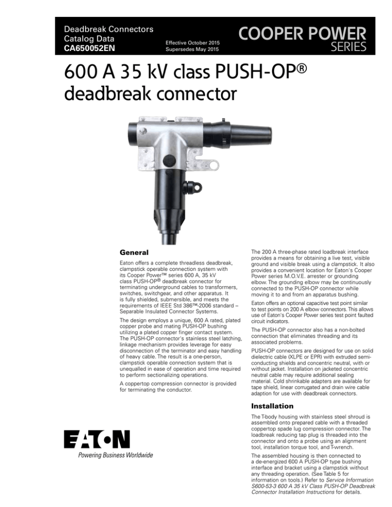
Eaton offers a complete threadless deadbreak,
clampstick operable connection system with
its Cooper Power™ series 600 A, 35 kV
class PUSH-OP® deadbreak connector for
terminating underground cables to transformers,
switches, switchgear, and other apparatus. It
is fully shielded, sub­mers­ible, and meets the
re­quirements of IEEE Std 386™-2006 standard –
Separable Insulated Connec­tor Systems.
The design employs a unique, 600 A rated, plated
copper probe and mating PUSH-OP bushing
utilizing a plated copper finger contact system.
The PUSH‑OP connector's stainless steel latching,
linkage mechanism provides le­ver­age for easy
dis­con­nec­tion of the terminator and easy handling
of heavy cable. The result is a one-person,
clampstick operable con­nec­tion system that is
unequalled in ease of operation and time re­quired
to perform sectionalizing operations.
A coppertop compression con­nec­tor is provided
for terminating the conductor.
The 200 A three-phase rated loadbreak interface
provides a means for obtaining a live test, visible
ground and visible break using a clampstick. It also
provides a convenient location for Eaton's Cooper
Power series M.O.V.E. arrester or grounding
elbow. The grounding elbow may be continuously
connected to the PUSH-OP connector while
moving it to and from an apparatus bushing.
Eaton offers an optional capacitive test point similar
to test points on 200 A elbow connectors. This allows
use of Eaton's Cooper Power series test point faulted
circuit indicators.
The PUSH-OP connector also has a non-bolted
connection that eliminates threading and its
associated prob­lems.
PUSH-OP connectors are de­signed for use on solid
dielectric cable (XLPE or EPR) with extruded semiconducting shields and con­cen­tric neutral, with or
without jacket. Installation on jacketed concentric
neutral cable may require additional sealing
material. Cold shrinkable adapters are available for
tape shield, linear corrugated and drain wire cable
adaption for use with deadbreak connectors.
Installation
The T-body housing with stainless steel shroud is
assembled onto prepared cable with a threaded
coppertop spade lug compression connector. The
loadbreak reducing tap plug is threaded into the
con­nec­tor and onto a probe using an alignment
tool, installation torque tool, and T-wrench.
The assembled housing is then connected to
a de-energized 600 A PUSH-OP type bushing
interface and bracket using a clampstick without
any threading operation. (See Table 5 for
information on tools.) Refer to Service Information
S600-53-3 600 A 35 kV Class PUSH-OP Deadbreak
Connector Installation Instructions for details.
Catalog Data CA650052EN
600 A 35 kV class PUSH-OP deadbreak connector
Effective October 2015
600 A PUSH-OP
BUSHING
LOCATING PINS
COMPRESSION
CONNECTOR 15/16 inch 9NS 2B
threaded coppertop compression
connector is sized to ensure a
cool running connector with maximum current transfer.
LOADBREAK REDUCING TAP PLUG is
200 A, single-phase loadbreak and threephase. Fault close rated.
COPPER PROBE ASSEMBLY
Field replaceable tin-plated
copper probe and STUD-T
assembly ensures reliable
electrical connection.
Installation of connector
assembly to PUSH-OP
bushing requires no threading.
SHROUD
Stainless steel (Series
300) shroud provides a
hotstick eye and the
locating pins for
connection to a PUSH-OP
type bushing tap.
CLAMPSTICK
EYE
SEMI-CONDUCTING INSERT
Molded semi-conducting insert
provides corona-free electro­static
shielding of the com­pres­sion connector.
CAPACITIVE TEST POINT
Capacitive test point (Optional)
allows use of Cooper Type
S.T.A.R. (TPR) Series Fault
Indicators.
SEMI-CONDUCTING SHIELD
Precision molded peroxide-cured semiconducting shield provides ground
shield continuity and meets the
requirements of IEEE Std 592™
standard.
DRAIN WIRE TAB
Drain wire tab provides a convenient point
to connect drain wire to ensure grounding
of the connector shield.
T-BODY
Molded T-body adapts to all
cable sizes and provides a
deadfront shielded connection.
CABLE ADAPTER
Molded cable adapter, sized
to fit cable insulation diameters
from 0.875 inch to 2.210 inches
(22.2 to 56.1 mm), provides stress
relief for the terminated cable.
EPDM INSULATION
High-quality peroxide-cured
EPDM Insulation is mixed
and formulated in-house for
complete control of raw
rubber char­ac­ter­is­tics.
Figure 1. PUSH-OP connector cutaway illustrates design integrity.
NNote: Dimensions given are for reference only.
Production tests
B
S3
A
Tests conducted in accordance with IEEE Std 386™-2006 standard:
C
S2
•
ac 60 Hz 1 Minute Withstand
• 50 kV
•
Minimum Partial Discharge Extinction Voltage
• 26 kV
S5
35 kV
D
Tests conducted in accordance with Eaton re­quire­ments:
A
18.1" (460 mm)
B
0.25" (6 mm)
C
0.25" (7 mm)
D
12.1" (307 mm)
S2
0.50" (13 mm)
Table 1. Voltage Ratings and Characteristics
S3
12.5" (317 mm)
Description
kV
S5
2.9" (72.14 mm)
Standard Voltage Class
35
Maximum Rating Phase-to-Phase (Bushing Insert Only)
36.6
•
Physical In­spec­tion
•
Periodic Dissection
•
Periodic Fluoroscopic Analysis
Maximum Rating Phase-to-Ground
21.1
Figure 2. PUSH-OP connector stacking dimensions.
AC 60 Hz 1 Minute Withstand
50
NNote: Dimensions given are for reference only.
DC 15 Minute Withstand
103
BIL and Full Wave Crest
150
Minimum Partial Discharge Extinction Voltage
26
Voltage ratings and characteristics are in accordance with IEEE Std 386™-2006 standard.
2
www.eaton.com/cooperpowerseries
Catalog Data CA650052EN
600 A 35 kV class PUSH-OP deadbreak connector
Effective October 2015
Catalog number selection
Table 2. Current Ratings and Characteristics
Description
Use the following procedure to develop the correct part number for
the desired PUSH-OP kit, based on cable size, conductor size and
desired options.
Amperes
600 A Interface
Continuous
600 A rms
24 Hour Overload
1,000 A rms
Short Time
40,000 A rms symmetrical for 0.17 s
Step 1 – Determine the cable’s diameter over the electrical
insulation as shown in Figure 3 (including tolerances). Then identify a
cable range from Table 3 that brackets the minimum and maximum
insulation diameters. Select the correct CABLE RANGE CODE.
27,000 A rms symmetrical for 4.0 s
Step 2 – Identify the conductor size and type in Table 4 and select
the CONDUCTOR CODE from the far right column.
200 A Interface*
Continuous
200 A rms
Switching**
10 operations at 200 A rms at 21.1 kV
Fault Closure
10,000 A rms symmetrical at 36.6 kV for 0.17 s after 10
switching operations
Short Time
10,000 A rms symmetrical for 0.17 s
Step 3 – For a PUSH-OP kit with a capacitive test point and
protective cap, order:
CABLE RANGE CONDUCTOR TC
POP635
CODE
CODE
For a PUSH-OP kit without a capacitive test point or protective cap,
order:
3,500 A rms symmetrical for 3.0 s
Current ratings and characteristics are in ac­cor­dance with IEEE Std 386™-2006 standard.
* If available system fault current exceeds 10 kA, current limiting fusing must be used upstream.
Otherwise fault close and short time ratings of the 200 A interface will be exceeded.
POP635 CABLE RANGE
CODE
**Switching rated limited to Single-phase 21.1 kV.
EXAMPLE: To select a PUSH-OP kit without a capacitive test point,
with a protective cap for a 250 kcmil compressed cable with a
nominal insulation diameter of 1.16".
Optional features
Insulated protective cap
200 A insulated protective cap fits over loadbreak reducing tap plug
for dead­front shielding.
Capacitive test point
Capacitive test point, on molded T-body, with snap-on cap, provides a
place to mount STVT, STLO and STHI test point faulted circuit indicators.
To order replacement compression connectors and cable adapters
for a PUSH-OP connector, see Catalog CA650006EN, “Deadbreak
Accessories, Tools and Replacement Parts”.
Ordering information
•
Molded Rubber T-body with stainless steel shroud
•
Loadbreak Reducing Tap Plug
•
Cable Adapter
•
Probe
•
Compression Connector
•
Silicone Lubricant
•
Installation Instruction Sheet
•
Copper Alloy Stud
METAL NEUTRAL
OR SHIELD
Step 1 – Nominal diameter over the insulation is 1.16" ± .030"
minimum diameter = 1.16 - .030 = 1.13"
maximum diameter = 1.16 + .030 = 1.19"
From Table 3 identify the cable range 1.13" - 1.19" and select the “H”
Cable Range Code.
Step 2 – The conductor size is a 250 kcmil compressed. From Table
4, under the column “Concentric or Compressed”, identify 250 kcmil
and select the “17” conductor code.
Step 3 – Order catalog number:
POP635H17C
Table 3. Cable Diameter Range
Each PUSH-OP Connector kit contains:
OUTER JACKET
CONDUCTOR
CODE
INSULATION
SHIELD
INSULATION
Inches
mm
Cable
Range
Code
Inches
mm
Cable
Range
Code
0.875-0.985
22.2-25.0
D
1.355-1.520
34.4-38.6
M
0.930-1.040
23.6-26.4
E
1.485-1.595
37.7-40.5
N
0.980-1.115
24.9-28.3
F
1.530-1.640
38.9-41.7
P
1.040-1.175
26.4-29.8
G
1.575-1.685
40.0-42.8
Q
1.095-1.240
27.8-31.5
H
1.665-1.785
42.3-45.3
R
1.160-1.305
29.5-33.1
J
1.755-1.875
44.6-47.9
S
1.220-1.375
31.0-34.9
K
1.845-1.965
46.9-50.0
T
1.285-1.395
32.5-35.4
L
1.960-2.210
49.8-56.1
U
DIAMETER OVER
INSULATION
CONDUCTOR
CONDUCTOR
SHIELD
Figure 3. Illustration showing typical construction of medium voltage underground
cable.
www.eaton.com/cooperpowerseries
3
Catalog Data CA650052EN
600 A 35 kV class PUSH-OP deadbreak connector
Effective October 2015
Table 4. Conductor Size and Type
Concentric or Compressed
Compact or Solid
AWG or kcmil
No Connector
3
AWG or kcmil
mm2
2
–
_
–
70
–
95
120
–
–
185
–
240
300
–
–
–
500
–
–
mm2
–
–
–
50
70
–
95
120
150
–
185
–
240
300
–
400
–
500
630
2
1
1/0
2/0
3/0
4/0
250
300
350
400
450
500
600
650b
750d
900
1000
1250
a.
b.
c.
d.
Also
Also
Also
Also
accepts
accepts
accepts
accepts
1
1/0
2/0
3/0
4/0
250
300
350
400
450
500a
600
700
750c
900
1000
–
–
CONDUCTOR
CODE
00
10
11
12
13
14
15
16
17
18
19
20
21
22
23
24
25
26
27
28
550 kcmil compact conductor.
700 kcmil compressed conductor.
800 kcmil compact conductor.
700 kcmil concentric conductor.
Figure 4. Catalog Number TWRENCH
The T-Wrench is used to install the loadbreak reducing tap plug
into the compression connector and T-body.
Figure 5. Catalog Number TQHD635
The Torque Tool is required to assemble a 35 kV Class PUSH‑OP
deadbreak connector. It is precision calibrated and hotstick
operable.
Table 5. Replacement Parts and Tools
Description
Catalog Number
T-body without Test Point with shroud
PDT635
T-body with Test Point with shroud
PDT635T
Loadbreak Reducing Tap Plug (includes Built-In Alignment Tool)
LRTP635
Probe and STUD-T Assembly
2638894B01B
200 A, 35 kV Class Insulated Protective Cap
LPC235
Installation Torque Wrench
TQHD635
5/16 inch T-Wrench
TWRENCH
See Catalog CA650006EN for replacement compression connectors, cable adapters and additional
information on tools.
Eaton
1000 Eaton Boulevard
Cleveland, OH 44122
United States
Eaton.com
Eaton’s Cooper Power Systems Division
2300 Badger Drive
Waukesha, WI 53188
United States
Eaton.com/cooperpowerseries
© 2015 Eaton
All Rights Reserved
Printed in USA
Publication No. CA650052EN
Eaton is a registered trademark.
All other trademarks are property
of their respective owners.
For Eaton's Cooper Power series product
information call 1-877-277-4636 or visit:
www.eaton.com/cooperpowerseries.


