c 4 M -W
advertisement
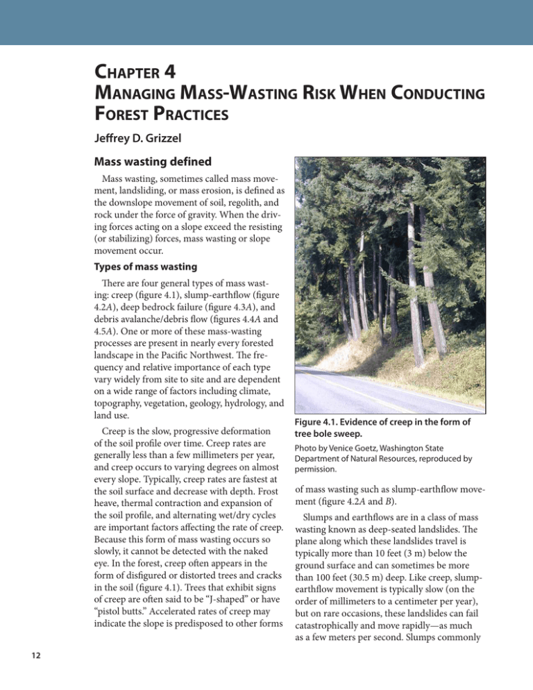
Chapter 4 Managing Mass-Wasting Risk When Conducting Forest Practices Jeffrey D. Grizzel Mass wasting defined Mass wasting, sometimes called mass movement, landsliding, or mass erosion, is defined as the downslope movement of soil, regolith, and rock under the force of gravity. When the driving forces acting on a slope exceed the resisting (or stabilizing) forces, mass wasting or slope movement occur. Types of mass wasting There are four general types of mass wasting: creep (figure 4.1), slump-earthflow (figure 4.2A), deep bedrock failure (figure 4.3A), and debris avalanche/debris flow (figures 4.4A and 4.5A). One or more of these mass-wasting processes are present in nearly every forested landscape in the Pacific Northwest. The frequency and relative importance of each type vary widely from site to site and are dependent on a wide range of factors including climate, topography, vegetation, geology, hydrology, and land use. Creep is the slow, progressive deformation of the soil profile over time. Creep rates are generally less than a few millimeters per year, and creep occurs to varying degrees on almost every slope. Typically, creep rates are fastest at the soil surface and decrease with depth. Frost heave, thermal contraction and expansion of the soil profile, and alternating wet/dry cycles are important factors affecting the rate of creep. Because this form of mass wasting occurs so slowly, it cannot be detected with the naked eye. In the forest, creep often appears in the form of disfigured or distorted trees and cracks in the soil (figure 4.1). Trees that exhibit signs of creep are often said to be “J-shaped” or have “pistol butts.” Accelerated rates of creep may indicate the slope is predisposed to other forms 12 Figure 4.1. Evidence of creep in the form of tree bole sweep. Photo by Venice Goetz, Washington State Department of Natural Resources, reproduced by permission. of mass wasting such as slump-earthflow movement (figure 4.2A and B). Slumps and earthflows are in a class of mass wasting known as deep-seated landslides. The plane along which these landslides travel is typically more than 10 feet (3 m) below the ground surface and can sometimes be more than 100 feet (30.5 m) deep. Like creep, slumpearthflow movement is typically slow (on the order of millimeters to a centimeter per year), but on rare occasions, these landslides can fail catastrophically and move rapidly—as much as a few meters per second. Slumps commonly CHAPTER 4: MANAGING MASS-WASTING RISK WHEN CONDUCTING FOREST PRACTICES exhibit rotational movement along an arc-like failure plane. As a result, they often consist of a series of intact, down-dropped blocks, and the surrounding ground has a “benchy” appearance (figure 4.2A and B). As the slump blocks move progressively farther downslope, they break apart to form an earthflow. While slump terrain is often benchy, earthflow terrain is often highly irregular and hummocky. In addition to benchy and hummocky ground, other indicators of slump-earthflow terrain include small, midslope ponds or wetlands, vertical scarps, ground cracks, exposed soils, and tipped or downed trees. Slumps and earthflows can be relatively small (<1 acre [0.4 ha]), or they can encompass hundreds or even thousands of acres. Because these types of landslides often move very slowly, slump-earthflow terrain can be covered with mature forests. These types of landslides often form where structurally weak materials overlie stronger, more erosion-resistant rocks or sediments. Like slumps and earthflows, deep bedrock failures are also classified as deep-seated landslides. The plane along which this type of landslide travels is often tens, and sometimes hundreds, of feet below the ground surface (figure 4.3A and B). As the name implies, this type of landslide involves large amounts of rock and commonly occurs along zones of weakness within the underlying bedrock. Deep bedrock failures can move very rapidly (meters per second) and can encompass large areas (hundreds or even thousands of acres). Debris avalanches and debris flows are shallow landslides in which the failure plane is within about 10 feet (3 m) of the ground surface. Typically, these types of landslides involve mostly soil and colluvium;1 rock comprises a relatively small fraction of the total landslide mass. Debris avalanches and debris flows move rapidly (as much as several meters per second) and typically begin in steep, convergent terrain. Debris avalanches begin on hillslopes and have 1 Unconsolidated, unsorted earth material deposited on sideslopes and/or at the base of slopes by mass movement (e.g., direct gravitational action) and by local, unconcentrated runoff. A B Figure 4.2. A, diagram of a slump-earthflow landslide; B, slump-earthflow along the North Fork Stillaguamish River in Snohomish County, Wash. Illustration courtesy of U.S. Geological Survey. Photo by author Jeffrey D. Grizzel. A B Figure 4.3. A, diagram of a deep bedrock failure; B, deep bedrock failure near the Columbia River Gorge in Washington. Illustration courtesy of U.S. Geological Survey. Photo by Don Nelsen, reproduced by permission. 13 BEST MANAGEMENT PRACTICES FOR MANAGING SOIL PRODUCTIVITY IN THE DOUGLAS-FIR REGION relatively low water content (figure 4.4A and B). In contrast, debris flows occur in steep-gradient stream channels, have high water content, and are very mobile (figure 4.5A and B). As a result, debris flows (sometimes called debris “torrents” or debris “floods”) can travel long distances (often several kilometers) from the point of initiation. Debris avalanches can transform into debris flows if the landslide mass enters a steep-gradient stream channel and becomes fluid-like. A B Factors affecting landslide initiation Mass wasting is a natural process, but land use practices such as forestry can increase the frequency and magnitude of this form of erosion. In natural or unmanaged settings, the following factors influence mass-wasting processes: • Hydrology: High-intensity rain or rain-on-snow storm events west of the Cascades and high-intensity summer thunderstorms east of the Cascades often initiate shallow landslides. Annual and seasonal variations in precipitation can influence creep rates and the movement of deep-seated landslides. • Vegetation: Forest canopies intercept and retain rain and snow, reducing soil moisture inputs. Forest canopies allow intercepted rain and snow to be evaporated back into the atmosphere, and trees withdraw or transpire water from the soil profile as part of their normal growth processes. Tree roots reinforce the soil profile, increasing its structural strength. • Geology: Parent materials affect the particle size distribution and mineralogy of overlying materials, weathering patterns, and resulting material strengths. Bedrock structure and associated jointing and fracturing influence faulting patterns. Figure 4.4. A, diagram of a debris avalanche; B, debris avalanche in southwest Washington. Illustration courtesy of U.S. Geological Survey. Photo by Dean Adams, Washington State Department of Natural Resources, reproduced by permission. A B Figure 4.5. A, diagram of a debris flow; B, multiple debris flows in southwest Washington. Illustration courtesy of U.S. Geological Survey. Photo by Dave Norman, Washington State Department of Natural Resources, Division of Geology and Earth Resources, reproduced by permission. 14 CHAPTER 4: MANAGING MASS-WASTING RISK WHEN CONDUCTING FOREST PRACTICES In managed settings, the following forestryrelated factors can increase the potential for certain forms of mass wasting: • Hydrology: Road construction and maintenance practices can alter natural hydrologic flowpaths. • Vegetation: Loss of vegetation results in reductions in canopy interception, evapotranspiration, and rooting strength. • Geology: Road cutslopes and fillslopes are often steeper than the natural slope angle, standard cut-and-fill construction techniques redistribute the slope-mass balance, and fill materials may not be adequately compacted. Risk analysis To effectively mitigate the effects of forest practices on mass-wasting potential, you must first analyze the risks present. Risk is a function of the mass-wasting hazard (the likelihood that mass wasting will occur) and the resulting consequences or degree of adverse impact (figure 4.6). Mass-wasting risk is low when there is a low likelihood of mass wasting and the degree of adverse impact is negligible. Mass-wasting risk is very high when there is a high likelihood of mass wasting and the degree of adverse impact is severe. identify and map (1) portions of your site with a moderate to very high landslide potential and (2) downslope or downstream resources that could be impacted by a landslide originating from your site. Step 2. Validate the preliminary hazard and consequence ratings by conducting a field review of your site. Do the site conditions reflect your preliminary hazard and consequence ratings? If not, where do adjustments need to be made? Are all downslope and downstream resources that could be impacted by a landslide accounted for? If not, supplement your original mapping. Step 3. Assign a final mass-wasting risk rating for the site. If the risk is something other than “low,” you should consider developing and implementing mitigation measures to reduce the potential for the proposed forest practices to trigger mass wasting. Analyzing mass-wasting (landslide) risk involves three steps that should be conducted in advance of initiating any forest practices activities on your site. Step 1. Review available data and information to establish a preliminary hazard and consequence rating. In this step, you review aerial photos, topographic maps, geologic maps, soil maps, landslide and hazard-zone mapping, pertinent published reports, and GIS-based digital elevation models. LiDAR-based (Light Detection and Ranging) digital elevation models for parts of western Washington can be obtained through the Puget Sound LiDAR Consortium: http://pugetsoundlidar.ess.washington.edu/. The objective is to use this data and information to Figure 4.6. Conceptual model of landslide risk expressed as a function of landslide hazard and consequences. Graph by author Jeffrey D. Grizzel. 15 BEST MANAGEMENT PRACTICES FOR MANAGING SOIL PRODUCTIVITY IN THE DOUGLAS-FIR REGION Mitigation requirements/options A wide range of mitigation measures can be implemented to reduce the potential for forest practices to trigger mass wasting. Some of these measures are mandatory (required by law) in some states. These measures vary in complexity and cost, and each approach should be tailored to the site or situation. Note that both Oregon and Washington State Forest Practices Rules may require that more complex measures be developed by a licensed engineering geologist. Figure 4.7. Avoiding operations in areas with high mass-wasting potential is the lowest-risk mitigation option and often results in a complex mosaic of buffers and harvested areas. Photo by David Parks, Washington State Department of Natural Resources, reproduced by permission. Figure 4.8. Yarding corridors often provide an effective alternative to road construction across unstable terrain. Photo by author Jeffrey D. Grizzel. 16 The lowest-risk mitigation option is to avoid operations on areas with a high likelihood of mass wasting. This option, commonly known as avoidance, excludes landslide-prone terrain from harvest areas and often results in a complex mosaic of buffers and harvest units (figure 4.7). Since high-hazard sites are avoided, the potential for harvesting or road construction activities to trigger mass wasting is relatively low. In areas prone to shallow landslides, thinning may be a reasonable alternative to clearcutting since it conserves rooting strength. Thinning also mitigates some of the hydrologic effects that may contribute to slope movement (e.g., reductions in interception and evapotranspiration). During thinning operations, take care to avoid scarring or damaging residual trees. The creation of narrow yarding corridors through unstable slope buffers often avoids otherwise necessary road construction (figure 4.8). You should locate the corridors in areas free of signs of instability to minimize the number and width of corridors as well as scarring and damage to trees along the corridor margins. Full-bench road construction ensures excavated materials (e.g., soil and rock) are not placed along the outer edge of the road where they could become saturated and trigger a landslide (figure 4.9). When constructing roads in steep or unstable terrain, always deposit excavated soil and rock in a stable location away from the outer edge of the road. Take care to ensure that road cutslopes are stable and do not pose a rockfall hazard to those traveling in the area. CHAPTER 4: MANAGING MASS-WASTING RISK WHEN CONDUCTING FOREST PRACTICES Where road construction across steepgradient streams is proposed, use of durable, angular rock as fill material helps prevent road failure if the culvert should become plugged (figure 4.10). The angular nature of the rock ensures the individual pieces interlock, forming a structurally sound crossing. If possible, the road grade atop the culvert should be dipped to prevent the stream from being diverted in the event the culvert inlet becomes obstructed. Key references and other resources Burns, S.F., T.M. Harden, and C.J. Andrew. 2007. Homeowner’s Guide to Landslides: Recognition, Prevention, Control, and Mitigation. Portland, OR: Portland State University. http://www.oregongeology. org/sub/Landslide/homeowners-landslide-guide.pdf. From the Oregon Department of Geology and Mineral Industries: Figure 4.9. Full-bench construction ensures that no unstable fill material is placed along the outside edge of the road and that hillslopes below the road remain at their natural angle of repose. Photo by author Jeffrey D. Grizzel. • Debris Flow Advisories and Warnings. http:// www.oregon.gov/DOGAMI/Landslide/debrisflow1. shtml. • GIS overview map of potential rapidly moving landslide hazards in western Oregon. http://www. oregongeology.org/sub/publications/IMS/ims-022/ ims-022.htm. • Landslide Hazards in Oregon. http://www.oregongeology.org/sub/publications/landslide-factsheet. pdf. • Statewide Landslide Information Database for Oregon (SLIDO). http://www.oregongeology.org/ sub/slido/index.htm. Sidle, R.C., A.J. Pearce, and C.L. O’Loughlin. 1985. Hillslope Stability and Land Use. Water Resources Monograph no. 11. Washington, D.C.: American Geophysical Union. Swanson, F.J., L.E. Benda, S.H. Duncan, G.E. Grant, W.F. Megahan, L.M. Reid, and R.R. Ziemer. 1987. Mass failures and other processes of sediment production in Pacific Northwest forest landscapes. p. 9–38 in Streamside Management: Forestry and Fisheries Interactions, E.O. Salo and T.W. Cundy (eds.). Contribution no. 57. Seattle, WA: Institute of Forest Resources, University of Washington. Figure 4.10. Dipped rock fills result in stable road prisms at stream crossings. Note the large-arch culvert, heavy-rock armoring, and minimal fill over the culvert. Photo by Rick Roames, Washington State Department of Natural Resources, reproduced by permission. Washington Forest Practices Board. 2004. Section 16 – Guidelines for Evaluating Potentially Unstable Slopes and Landforms. Olympia, WA: Washington State Department of Natural Resources, Forest Practices Division. 17
