From: FLAIRS-01 Proceedings. Copyright © 2001, AAAI (www.aaai.org). All rights reserved.
An AutomatedApproachto Post-Flight Simulation Analysis and
Validation Using Stochastic Optimization Methods
MurrayB. Anderson, Ph.D.
Director, AdvancedTechnologies and Studies Department
Sverdrup Technology Inc./TEAS Group
murray.anderson@,eglin.af.mil
Abstract
Withthe advent of streamlinedacquisition processes, such
as simulation-basedacquisition, the need for superior
weaponsimulation capability is critical to developing
launchand jettison envelops.Giventhe limited test assets
allocated to envelopdevelopment,
certification agenciesare
today being asked by newweaponsprogramsto developthe
same large envelops produced10 years ago with only 10
percent of the assets. Anadditional complicationis that
weaponsystems are becomingincreasingly complex:nonaxisymmetric, unstable or nearly unstable at launch,
employed from weapons bays, employed at very high
angles of attack. Giventhese complexities,it is becoming
increasing commonfor weaponsto exhibit non-linear
and/or highly coupledbehaviorduring launch or jettison
events. For the engineer,havinga systemthat behavesin a
non-linearfashiongreatly complicatespost-flight analysis.
It is critical, therefore, to havetools available that can
optimize a large numberof independent variables to
producethe desired output. This paperintroduces one such
tool andshowsits applicationto sampleflight test data.
Introduction
Verification of launch/jettison performance predictions
requires implementation of accurate mathematical models
of the weaponaerodynamics, the aircraft interference
flowfield contributions, the ejector performance,the flight
control system, and knowledge of the actual flight
conditions at launch. A number of parameter estimation
methods, such as maximum
likelihood, linear regression,
and Kalmanfilter, among others, have been applied to
flight data t’~ to examine the fidelity of these models.
Iterative gradient-based procedures are usually invoked,
beginning with initial estimates of the parameters, to
modify the parameter estimates until convergence is
achieved. With noise included in the measurements,
uniqueness of the parameter set is not guaranteed for a
minimumerror solution, since, in general, different
combinations of parameters mayproduce solutions having
equivalent, least-squares differences relative to the data.
The complications introduced by including non-linear and
highly-coupled
aerodynamic behavior into the
optimization process make gradient-based methods even
less attractive
because these complications almost
guarantee the presence of local optima. Stochastic
optimization techniques are free from the limits imposed
by gradient-based methods. Since transition rules are not
deterministic but stochastic, techniquesthat use probability
theory to decide whichpart of the solution space to sample
next have the ability to broadly sample the optimization
space of interest and develop a non-linear multidimensional mappingof the optimization space. Probably
the most popular stochastic optimization scheme in use
today is genetic algorithms. Although popular for years
4,
for control system studies (Norris and Crossley
McGookin s, Homaifar and McCormick6), genetic
algorithms have really not penetrated the flight test and
simulation validation/verification
community until
recently 7’s. Genetic algorithms (GAs) will not
described in this paper, but it is important to knowthe type
of algorithm used. For this study an elitist Pareto GAis
used to operate on two goals (defined below). The
population size was 100, the crossover probability was
90%and the mutation rate was 0.5%. Creep mutation was
also used at a rate of 5%,meaningthat 5%of the variables
could creep at any time.
Definition of Optimization Goals
In order to get a simulation to matchflight test data, it is
important that the goals be properly defined. During the
separation event, whether jettison or active launch, there
are two main objectives when attempting to get a
simulation to match flight test data: minimize position
errors, minimizeattitude errors. Performanceestimates for
the attitude and position goals are based on determining
the root-mean-square (RAMS)difference betweenthe flight
test telemetry data and the current simulation attempt at
reproducingthe flight test data.
Copyright
©2001,American
Association
for ArtificialIntelligence
(www.aaai.org).
Allrightsreserved.
AI IN AEROSPACE19
Interference Flow Field and Freestream
Aerodynamic Data
Rather than use actual flight test data for this study, a
conventional six-degree-of-freedom (6DOF) generated
"simulated" flight test data using defined interference flow
field and freestream aerodynamic models. There are two
major advantages to this approach. First, since this is a
process study to explore the performance of an
optimization algorithm, knowingthe "right" answers if of
critical
importance to evaluating the algorithm’s
performance during the solution process. Second, there
are no public-release
issues involved when using
"simulated" flight test data. The "simulated" flight test
data used for this demonstration were, however, based on
real flight test experience for a real weaponsystem. From
this point forward, these data will be referred to as flight
test data.
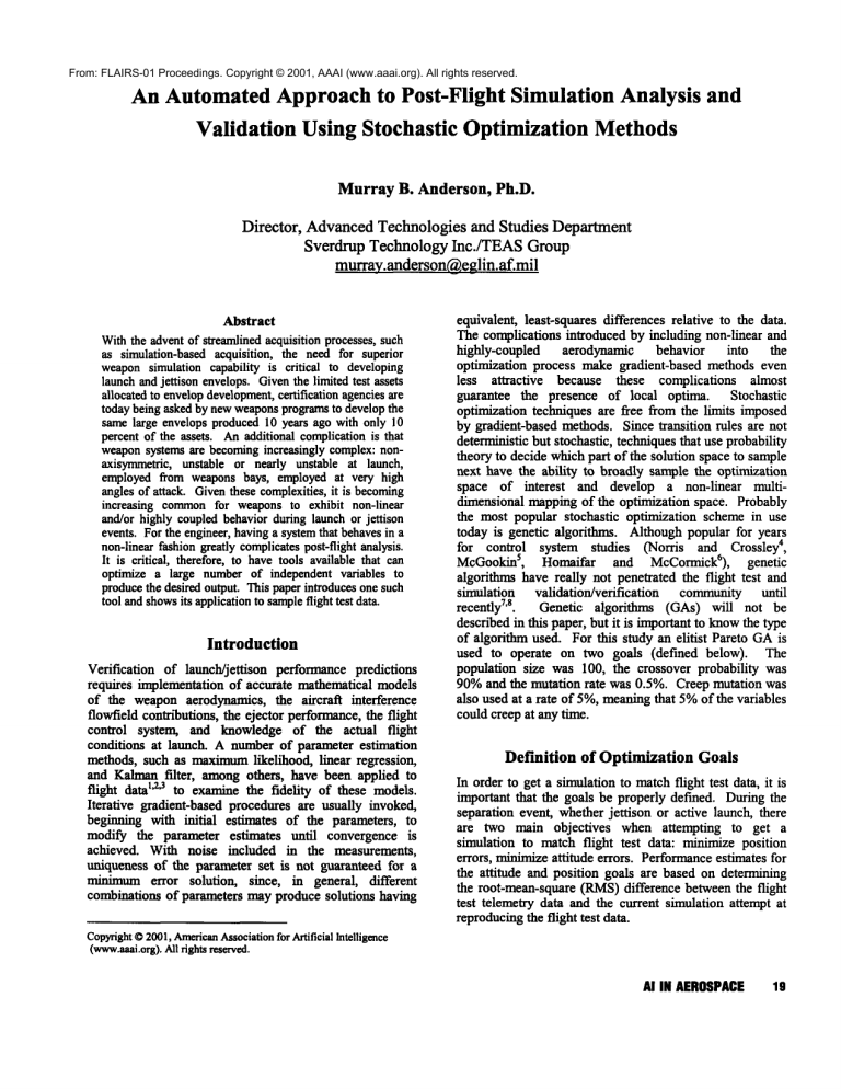
Table 1. Ejector, Inertial, and Freestream Aerodynamic
Factors
fwdfac
afffac
xinerfac
yinerfac
zinerfac
The aircraft interference data was modeled as force and
momentincrements which decayed exponentially to zero
after the weapontraversed 30 feet from the launch point.
The freestream aerodynamicdata were statically unstable
in pitch and yaw,and neutrally stable in roll.
Ejector Model
The ejector was modeled as a force versus displacement
model that had the capability to distribute the load as
desired between the forward and aft foot of the ejector.
This type of model is very representative of actual
hardware.
caoff
cyoff
czoff
cmoff
cnoff
Multiplication factor
governing amount
of force applied to
forward ejector foot
Multiplication factor
governing amount
of force applied to
aft ejector foot
roll inertia
multiplier
pitch inertia
multiplier
yawinertia
multiplier
freestream axial
force coefficient
offset (f.c.o)
freestream side f.c.o
freestream vertical
f.c.o.
freestream pitching
momentcoefficient
offset (nxc.o.)
freestream yawing
0.2
1.0
0.025
5
0.2
1.0
0.025
5
0.9
1.1
0.02
4
0.9
1.1
0.02
4
0.9
1.1
0.02
4
-0.1
O.1
0.01
5
-0.2
-0.2
0.2
0.2
0.01
0.01
6
6
-0.5
0.5
0.02
6
-0.5
0.5
0.02
6
-0.5
0.5
0.02
6
0.25
2.0
0.05
6
0.25
2.0
0.05
6
0.25
2.0
0.05
6
0.25
2.0
0.05
6
0.25
2.0
0.05
6
0.25
2.0
0.05
6
m.c.o.
cloff
freestream rolling
m.C.O.
Optimization Variables
There were 17 input variables to the simulation that the
genetic algorithm was forced to include in the optimization
process. The genetic algorithm also requires specification
of the maximumand minimumbounds that each value can
take, and the desired resolution of parameter. For this
study, the variables and boundsfound in Table 1 were used
in the optimization process. Given these parameter bounds
" 1e answers
and resolution requirements, there are932 pnsmb
to this optimization problem.
caintfac
cyintfac
czintfac
cmintfac
cnintfac
interference axial
force coefficient
multiplier (f.c.m.)
interference side
f.c.m.
interference vertical
f.c.m.
interference pitching
momentcoefficient
multiplier (m.c.m.)
interference yawing
nLc.m.
clinffac
interference rolling
nLc.m.
Results
To better gauge how well the new post-flight analysis
approachworks, it will be compareddirectly against a "hill
climbing" gradient optimization approach. Gradient
methods have been the standard way to perform
20
FLAIRS-2001
optimization problemssuch as this one for manyyears.
However,for highly non-linear optimization problems,the
advantages of this new approach will become readily
apparent.
Figure 3 showsthe roll angle comparison.The hill climber
missedthe initial roll to the right andlackedoverall trend
performance. The genetic algorithm mimickedthe flight
test data very well. Even the fairly complexroll motion
(right-left-right) is captured
nearlyexactly.
Figure 1 showsthe Euler pitch angle history for the hill
climber and the genetic algorithmcomparedto flight test
data. The hill climber obviously got stuck in a local
optimaand did not comparenearly as well with the flight
test data than the genetic algorithm.Forgettingthe genetic
algorithmcomparisonfor a moment,it could be said that
the hill climbercapturedthe right "trend".EngineersoRen
talk about trend comparisonswith the actual comparisons
are not as goodas they wouldlike.
~n
o.
0
-5O
%,
-1110
I0
o.,
,.,
,.°
o.,
#"
"-¢
,°
12
Gene,c
[
-
~,.
- Hill Climber|
-150
0.o.°¯ J.o
..".."i
-I,
Time(sec)
-°.%
°°
%°’"....
......
o°OO""
Figure 3. Euler Roll Angle Comparison
i
Thetrajectory of the vehicle wascapturedvery well by the
genetic algorithm. The downrangecomparison(Figure 4)
shows that either methodworkswell, but since downrange
is typically the least importanttrajectory direction for
safety of flight it is best to look at lateral andvertical
vehicle movement
relative to the launchpoint.
-4o
-50
--
-6o
Time(sec)
Figure1. Euler Pitch Angle Comparison
The yawangle history plot, Figure 2, shows muchbetter
performance
by the hill climber, however,it is still not as
good as the genetic algorithm. Both methodsprovide very
reasonableyawbehaviorfor the vehicle.
T,°.(.o,
’i1
..............................................
° T
....
-20
/
’.
200.
X.50
180.
[’’"
Hill
Climber
J
-6O.
160.
-7O.
140¯,
120--~
’m
a.
-80.
#*’/
--~
n .....
t
¯
m
m
l®.-! * Genetic
w-----
/
t -°- Hill C,imberJ
q’r’**’"
i
/
Figure 4. DownrangeComparison
6o.-4o.--
o!
0.2
0.4
06
Time(sec)
011
Figure 2. Euler YawAngle Comparison
1.;
In the altitude and crossrange histories (Figure 5 and
Figure 6) the strength of the genetic algorithm becomes
readily apparent.Both lateral and vertical vehicle motion
is capturednearly perfectly by the genetic algorithm.The
hill climberactually performedfairly well, capturingboth
trends and magnitudesreasonably, but whencomparedto
the genetic algorithmthe hill climber does not look very
good.
AI IN AEROSPACE21
The gains evidenced by the genetic algorithm are not,
however, without cost. The hill climber found its answer
s0
so
Flight
Test
I
°*
t
"/-~"
Genetic
- -HI Clmber
2O
I0
0.2
oA
o.6
t
o.s
t.2
Time1~1
Figure 5. Crossrange Comparison
5.~O
m
4,leo
i
4.m
4.940
finding reasonable values. Both methods missed the
freestream axial force coefficient offset and the hill
climber missed the "normal" force coefficient badly. The
performance of each method for the freestream moment
coefficient offsets was mixed. Both methods missed the
"true" negative pitching momentoffset. The genetic
algorithm was closest on the yawing momentoffset, and
the hill climber was nearly perfect on the rolling moment
offset. It is interesting to note that although the hill
climber worked so well in finding the rolling moment
coefficient offset, the roll angle performanceof the hill
climber was not good (recall Figure 3). For strongly
coupled yaw-roll behavior, it is necessary to find
reasonable parameter values in more than one variable to
capture complexmotion.
The interference flow field contributions to the vehicle
motion show generally better performance by the genetic
algorithm when compared to the hill climber. Most
noticeable is the "normal" force contribution difference,
where the hill climber performed poorly. The genetic
algorithm worked muchbetter than the hill climber in
pitching and yawing moment coefficients.
The hill
climber was closer to the "truth" model than the genetic
algorithm for the rolling momentcontribution. The hill
climber workedbetter than the genetic algorithm in both
the freestream and interference
rolling
moment
contributions, but still the genetic algorithm workedbetter
in overall roll motion. It is possible that the genetic
algorithm’s underestimation of the freestream rolling
moment coefficient
contribution
could have been
compensatedby the overprediction of the interference flow
field’s contribution.
4.9~
4,900
m
4,m
0.2
0A
0,6
Time (sec)
08
’I
i
d/
t
I
¢n~fm
I
Figure 6. Altitude Comparison
1
I
¢a~l~m
in roughly 500 simulation runs (roughly 2 hours of CPU
time). The genetic algorithm answer was generated in
50,000 simulation runs (500 generations with 100
membersper generation).
oVff
~pm
22
FLAIRS-2001
I
III GeneiJc
¯ ~!ne
ea~
~m
A natural question to ask at this point is: what kind of
parameter values did the two optimization approaches
find?
Figure 7 shows the values found for each parameter
compared to the "baseline" or truth model. One of the
most noticeable differences is also one of the most
important for a separation event: the ejector forces. The
genetic algorithm found nearly perfect values for the
ejector force factors. The hill climber had difficulty
n Pill Qiml~"F~ I
-0.5
0,5
Figure 7. Factor Comparison
1,5
2
Finally, the inertia factors found by both methods were
close to the "truth" model.
It is interesting that there is such a dramatic difference in
vehicle motion given the genetic factors versus the hill
climber factors. Yet for complex aerodynamics, and given
a vehicle that is unstable at launch, differences early in a
trajectory can dramatically influence motiona secondafter
launch. It is also interesting that someof the genetic
algorithm factors can be in error significantly (like
interference flow field rolling momentcoefficient factor)
and yet the overall vehicle motion is captured nearly
perfectly. This would indicate that many parameter
combinations are capable of producing reasonable
trajectories.
For a complex non-linear aerodynamic
optimization problemthis should be the expected result.
Conclusions
The genetic algorithm is a dramatic improvementover the
popular hill climbing approach, but the parameter values it
obtains can still be in error. There is a possibility that
parameter combinations can compensatesomewhatfor each
other, leading to finding a "good"local optima rather than
the global optima. Given the way a genetic algorithm
operates, .it is inevitable that moregenerations wouldhave
eventually producedthe "global" optima. But at what cost?
The .solution found by the genetic algorithm in 500
generations worked well for each of the six degrees of
freedom,with parametervalues that are not unreasonablefor
a flight test program. Were this a real flight test
comparison, such good agreement between the simulation
and the flight test data wouldbe sufficient to proceed with
future missions with increased confidence. The hill climber
results, although generally capturing the correct trends,
would not inspire nearly as much confidence in the
sinmlation.
5. McGookin, E.W., Murray-Smith, D.J., Li, Y., and
Fossen, T.I., "Parameter Optimisation of a Non-linear
Tanker Control System Using Genetic Algorithms,"
Proceedings of the 2nd IEE/IEEEInternational Conference
on Genetic Algorithms in Engineering Systems, Glasgow,
United Kingdom, 1997.
6. Homaifar, A., McCormack,E.D., "Full Design of Fuzzy
Controllers
Using Genetic Algorithms," NASA-N9319452 06-80, The NASACenter for Aerospace Research
at North Carolina A&TState University, 1992.
7. Anderson, M.B., McCurdy, R.E., "Weapon Drag
Coefficient Determination Using Genetic Algorithm",
AIAApaper 94-3468, presented at the 1994 Atmospheric
Flight Mechanics Conference, Scottsdale, AZ., August
1994.
8. Anderson, M.B., and Lawrence, W.R., "Launch
Conditions and Aerodynamic Data Extraction By An
Elitist Pareto Genetic Algorithm", AIAAPaper 96-3361,
presented at the AIAAAtmospheric Flight Mechanics
Conference, San Diego, CA, July 1996.
References
1. Iliff, K. W., "ParameterEstimation for Flight Vehicles,"
AIAAJournal of Guidance, Control, and Dynamics, Vol.
12, No. 5, Sept-Oct 1989, pp. 609-622.
2. Chapman, G.T. an~ D.B. Kirk, "A Method for
Extracting Aerodynamic Coefficients from Free-Flight
Data," AIAAJournal, Vol. 8, No. 4, April 1970.
3. Welsh, C.J. and W.R. Lawrence, "Motion Analysis
Procedure for As~etric Vehicles," AEDC-TR75-153,
May 1976, IAA 3rd Atmospheric Flight Mechanics
Conference, June 1976.
4. Norris, S.R., and Crossley, W.A., "Pareto-Optimal
Controller Gains Generated by a Genetic Algorithm,"
AIAA-98-1010, AIAAAerospace Sciences Meeting and
Exhibit, Reno, NV,1998.
AIIN AEROSPACE 23

