IF 1506 ELPS Light-Pak Emergency Lighting Fixture Series
advertisement

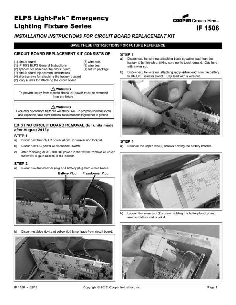
ELPS Light-Pak™ Emergency Lighting Fixture Series IF 1506 INSTALLATION INSTRUCTIONS FOR CIRCUIT BOARD REPLACEMENT KIT SAVE THESE INSTRUCTIONS FOR FUTURE REFERENCE CIRCUIT BOARD REPLACEMENT KIT CONSISTS OF: (1) (1) (2) (1) (4) (2) circuit board (2) wire nuts IF 1072 ELPS General Instructions (2) wire ties spacers for attaching the circuit board (1) return package circuit board replacement instructions short screws for attaching the battery bracket long screws for attaching the circuit board STEP 3 a) Disconnect the wire nut attaching black negative lead from the battery to battery plug, taking care not to touch ground. Cap lead with a wire nut. b) Disconnect the wire nut attaching red positive lead from the battery to ON/OFF selector switch. Cap lead with a wire nut. WARNING To prevent injury from electric shock, all power must be removed from the fixture. WARNING Even after disconnect, batteries will still be live. To prevent electrical shock and explosion, take extra care not to touch leads together or to ground. EXISTING CIRCUIT BOARD REMOVAL (for units made after August 2012): STEP 1 a) Disconnect branch AC power at circuit breaker and lockout. STEP 4 b) Disconnect DC power at disconnect switch. a) Remove the upper two (2) screws holding the battery bracket. c) After removing all AC and DC power to the fixture, remove all cover fasteners to gain access to the interior. b) Loosen the lower two (2) screws holding the battery bracket and remove battery and bracket. STEP 2 a) Disconnect transformer plug and battery plug from circuit board. Battery Plug b) Transformer Plug Disconnect blue (L+) and yellow (L-) lamp leads from circuit board. IF 1506 • 09/12 Copyright © 2012, Cooper Industries, Inc. Page 1 STEP 5 a) NEW CIRCUIT BOARD RE-INSTALLATION: Disconnect two (2) yellow leads from normally open contacts of pushbutton assembly. STEP 1 Insert new circuit board securing with two (2) long screws and spacers. STEP 2 Connect one (1) black wire from circuit board with one (1) black wire from pilot light with a wire nut. Connect one (1) white wire from the circuit board to one (1) white wire from the pilot light with a wire nut. Connect two (2) yellow leads to normally open contacts of pushbutton assembly. STEP 3 Insert battery, fastening battery bracket with four (4) screws. STEP 4 b) Remove wire tie and disconnect wire nuts attaching one (1) black and one (1) white wire lead from the indicating pilot light to the circuit board. Attach red positive lead of the battery to red lead of the ON/OFF switch with a wire nut. Attach black negative lead of the battery to black lead of the battery plug with a wire nut. STEP 5 Connect blue (L+) and yellow (L-) lamp leads to circuit board. Connect transformer plug and battery plug to circuit board. STEP 6 Replace cover and bolts. Torque to 30 ft.-lbs. Remove lockout, then connect DC power at switch and AC power at circuit breaker. After power is restored, the light will blink continuously to recharge for 48 hours. After that time, it should remain on steady. STEP 7 Return the original circuit board in the postage-paid packaging provided. STEP 6 Remove two (2) screws and spacers holding the circuit board in place and remove the circuit board. All statements, technical information and recommendations contained herein are based on information and tests we believe to be reliable. The accuracy or completeness thereof are not guaranteed. In accordance with Cooper Crouse-Hinds "Terms and Conditions of Sale," and since conditions of use are outside our control, the purchaser should determine the suitability of the product for his intended use and assumes all risk and liability whatsoever in connection therewith. Cooper Crouse-Hinds, LLC PO Box 4999, Syracuse, New York 13221 • U.S.A. Copyright © 2012, Cooper Industries, Inc. IF 1506 Revision 3 Revised 09/12 Supercedes 12/10


