Capacitor Switch
Functional Specification Guide
G230-50-1
Edison Capacitor Switch
Functional Specification for 15 kV or 25 kV Capacitor Vacuum Switch
1. Scope
1.1. Single-phase, electrically operated vacuum switch with close and latch capability. The Edison Capacitor
Switch is intended for application on up to 15.6 kV ungrounded WYE systems or 27 kV solidly grounded
WYE systems for the 15 kV rated switch, and 25 kV ungrounded WYE systems or 38 kV solidly grounded
WYE systems for the 25 kV rated switch
1.2. This specification shall only cover the purchase and shipment of the switch. The purchaser and/or user shall
be responsible for all site-work, electrical connections, and installation.
2. Applicable Standards
2.1. IEEE Std C37.66™-2005 standard – IEEE Standard Requirements for Capacitor Switches for AC Systems
(1 kV to 38 kV).
2.2. IEC 62271-103, 2011 – High-Voltage Switchgear and Controlgear – Part 103: Switches for Rated Voltages
above 1 kV up to and including 52 kV.
3. Ratings
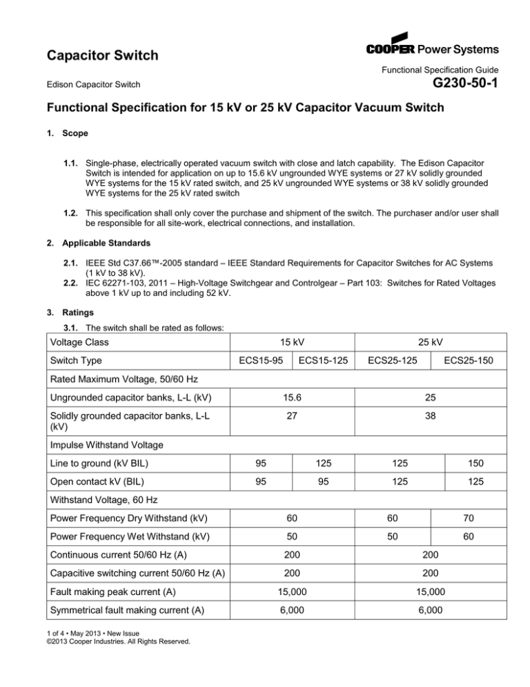
3.1. The switch shall be rated as follows:
Voltage Class
Switch Type
15 kV
ECS15-95
25 kV
ECS15-125
ECS25-125
ECS25-150
Rated Maximum Voltage, 50/60 Hz
Ungrounded capacitor banks, L-L (kV)
15.6
25
Solidly grounded capacitor banks, L-L
(kV)
27
38
Impulse Withstand Voltage
Line to ground (kV BIL)
95
125
125
150
Open contact kV (BIL)
95
95
125
125
Withstand Voltage, 60 Hz
Power Frequency Dry Withstand (kV)
60
60
70
Power Frequency Wet Withstand (kV)
50
50
60
Continuous current 50/60 Hz (A)
200
200
Capacitive switching current 50/60 Hz (A)
200
200
Fault making peak current (A)
15,000
15,000
Symmetrical fault making current (A)
6,000
6,000
1 of 4 • May 2013 • New Issue
©2013 Cooper Industries. All Rights Reserved.
Edison Capacitor Switch
G230-50-1
Withstand peak current (A)
15,000
15,000
Short-time symmetrical withstand current
(A)
4,500
4,500
High frequency transient making peak
current (A)
9,000
9,000
Rated transient inrush frequency (Hz)
6,000
6,000
Creepage Distance
Terminal to terminal (mm)
440
600
813
813
Terminal to ground (mm)
498
610
610
813
Operating Voltage Range, 50/60 Hz
110/120 Vac (V)
75 - 130
75 - 130
240 Vac (V)
150 - 260
150 - 260
110/120 Vac for 100 msec (A)
9
9
240 Vac for 100 msec (A)
6
6
Nominal Control Current
Weight (lb/kg)
32/14
Operating temperature range
Mechanical operations
33/15
33/15
34/16
-40 °C to +60 °C
-40 °C to +60 °C
50,000
50,000
3.2. The switchgear shall have an ambient operating temperature range of -40 ºC to +60 ºC.
3.3. Operating Duty Test (IEEE Std C37.66™-2005 standard, section 6.5)
200 A
100 A
35 A
400 operations
400 operations
400 operations
4. Switch Features
4.1. The switch shall be maintenance free. No routine maintenance is required.
4.2. The switch shall be operable in any mounting orientation.
4.3. The switch shall withstand a minimum of 50,000 mechanical operations (one operation equals one open
operation plus one close operation).
4.4. 15 kV switch can be designed up to 610 mm terminal to ground creepage. The 25 kV can be a designed up
to 813 mm terminal to ground creepage.
4.5. Switch is designed for optional type A, B, or C auxiliary contacts.
2 of 4 • May 2013 • New Issue
©2013 Cooper Industries. All Rights Reserved.
Edison Capacitor Switch
G230-50-1
4.6. Load side termination ring designed for 360 degree terminations (no need to break seals to rotate head for
directional connections). Design also allows for termination of multiple loads.
4.7. Bushing constructed of low viscosity cycloaliphatic epoxy resin. Designed to IEC 60815 SPS class E.
4.8. Tank made from fiberglass reinforced polyester (non-corrosive). Tank bears no structural loading, it is an
environmental shield only. Tank contains integrated rain shield and hot stick guide over the manual
operating handle.
4.9. Permanent Magnetic Solenoid design for robust mechanical operation (no cams, linkages, struts, or pins).
No relays or switching electronics allowed in the body of the switch.
4.10. Optional accessories include bird guards for all terminals, auxiliary contacts, and additional load terminals
4.11. Open/Closed indication integrated into manual operating handle
4.12. Mounting bracket made from type 304 stainless steel.
4.13. Nameplate:
Catalog Number
Serial Number
Rated maximum voltage, kV
Maximum system voltage with ungrounded capacitor neutral
Maximum system voltage with grounded system and grounded capacitor neutral
BIL Rating terminal to terminal
Creepage terminal to terminal
BIL Rating terminal to ground
Creepage terminal to ground
Rated continuous current, A (RMS)
Rated AC capacitive switching current (RMS)
Rated control voltage
Reference to wiring diagram documentation
Manufacturer, Date of Manufacture and Location of Manufacture
Rated short-time symmetrical current
Rated high-frequency transient making current
5. Certified Design Test Data:
5.1. Certified Design Test per IEEE Std C37.66™-2005 standard, section 6
6. Production Testing - The unit shall be subjected to the following production tests:
6.1. Production test per IEEE Std C37.66™-2005 standard, section7
7. Submittals
7.1. The manufacturer shall furnish instruction manuals covering the installation and operation of the switch.
8. Quality Assurance
8.1. Equipment shall be built in accordance with the industry standards for medium voltage equipment.
8.2. The manufacturer shall be registered and certified as ISO 9001 compliant by a recognized international and
independent body.
3 of 4 • May 2013 • New Issue
©2013 Cooper Industries. All Rights Reserved.
Edison Capacitor Switch
G230-50-1
9. Warranty
9.1. The switch shall be provided with a one-year warranty in-service or18 months maximum from date of
shipment.
10. Approved Manufacturers
Cooper Power Systems
4 of 4 • May 2013 • New Issue
©2013 Cooper Industries. All Rights Reserved.


