Voltage Regulators
MN225013EN
Effective February 2015
New Issue
COOPER POWER
SERIES
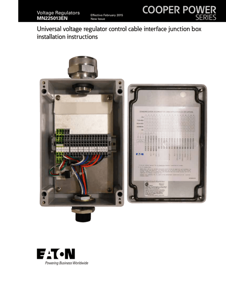
Universal voltage regulator control cable interface junction box
installation instructions
DISCLAIMER OF WARRANTIES AND LIMITATION OF LIABILITY
The information, recommendations, descriptions and safety notations in this document are based on Eaton Corporation’s
(“Eaton”) experience and judgment and may not cover all contingencies. If further information is required, an Eaton sales
office should be consulted. Sale of the product shown in this literature is subject to the terms and conditions outlined in
appropriate Eaton selling policies or other contractual agreement between Eaton and the purchaser.
THERE ARE NO UNDERSTANDINGS, AGREEMENTS, WARRANTIES, EXPRESSED OR IMPLIED, INCLUDING WARRANTIES
OF FITNESS FOR A PARTICULAR PURPOSE OR MERCHANTABILITY, OTHER THAN THOSE SPECIFICALLY SET OUT IN ANY
EXISTING CONTRACT BETWEEN THE PARTIES. ANY SUCH CONTRACT STATES THE ENTIRE OBLIGATION OF EATON. THE
CONTENTS OF THIS DOCUMENT SHALL NOT BECOME PART OF OR MODIFY ANY CONTRACT BETWEEN THE PARTIES.
In no event will Eaton be responsible to the purchaser or user in contract, in tort (including negligence), strict liability or otherwise for any special, indirect, incidental or consequential damage or loss whatsoever, including but not limited to damage or
loss of use of equipment, plant or power system, cost of capital, loss of power, additional expenses in the use of existing
power facilities, or claims against the purchaser or user by its customers resulting from the use of the information, recommendations and descriptions contained herein. The information contained in this manual is subject to change without notice.
ii
Control cable interface junction box installation instructions MN225013EN February 2015 www.cooperpower.com
Contents
SAFETY INFORMATION
Safety Information . . . . . . . . . . . . . . . . . . . . . . . . . . . . . . . . . . . . . . . . . . . . . . . . . . . . . . . . . . . . . . . . . . . . . . . . . . . . . . iv
PRODUCT INFORMATION
Introduction . . . . . . . . . . . . . . . . . . . . . . . . . . . . . . . . . . . . . . . . . . . . . . . . . . . . . . . . . . . . . . . . . . . . . . . . . . . . . . . . . . . 1
Acceptance and Initial Inspection . . . . . . . . . . . . . . . . . . . . . . . . . . . . . . . . . . . . . . . . . . . . . . . . . . . . . . . . . . . . . . . . . . 1
Handling and Storage . . . . . . . . . . . . . . . . . . . . . . . . . . . . . . . . . . . . . . . . . . . . . . . . . . . . . . . . . . . . . . . . . . . . . . . . . . . 1
Standards . . . . . . . . . . . . . . . . . . . . . . . . . . . . . . . . . . . . . . . . . . . . . . . . . . . . . . . . . . . . . . . . . . . . . . . . . . . . . . . . . . . . 1
PARTS SUPPLIED
Kit Part Contents . . . . . . . . . . . . . . . . . . . . . . . . . . . . . . . . . . . . . . . . . . . . . . . . . . . . . . . . . . . . . . . . . . . . . . . . . . . . . . . 2
INSTALLATION PROCEDURES
Removal of Existing Control Box . . . . . . . . . . . . . . . . . . . . . . . . . . . . . . . . . . . . . . . . . . . . . . . . . . . . . . . . . . . . . . . . . . . 2
Removal of Existing Control Cabinet . . . . . . . . . . . . . . . . . . . . . . . . . . . . . . . . . . . . . . . . . . . . . . . . . . . . . . . . . . . . . . . . 2
Universal Control Cable Interface Junction box Installation . . . . . . . . . . . . . . . . . . . . . . . . . . . . . . . . . . . . . . . . . . . . . . 3
Electrical Connections to the Universal Junction Box . . . . . . . . . . . . . . . . . . . . . . . . . . . . . . . . . . . . . . . . . . . . . . . . . . . 9
Operations Counter Connections . . . . . . . . . . . . . . . . . . . . . . . . . . . . . . . . . . . . . . . . . . . . . . . . . . . . . . . . . . . . . . . . . 12
Motor Capacitor Connections . . . . . . . . . . . . . . . . . . . . . . . . . . . . . . . . . . . . . . . . . . . . . . . . . . . . . . . . . . . . . . . . . . . . 13
Control cable interface junction box installation instructions MN225013EN February 2015 www.cooperpower.com
iii
!
Safety for life
SAFETY
FOR LIFE
!
SAFETY
FOR LIFE
Eaton meets or exceeds all applicable industry standards relating to product safety in its Cooper Power™ series products.
We actively promote safe practices in the use and maintenance of our products through our service literature, instructional
training programs, and the continuous efforts of all Eaton employees involved in product design, manufacture, marketing,
and service.
We strongly urge that you always follow all locally approved safety procedures and safety instructions when working around
high voltage lines and equipment, and support our “Safety For Life” mission.
Safety information
The instructions in this manual are not intended as a
substitute for proper training or adequate experience
in the safe operation of the equipment described.
Only competent technicians who are familiar with this
equipment should install, operate, and service it.
Safety instructions
Following are general caution and warning statements that
apply to this equipment. Additional statements, related to
specific tasks and procedures, are located throughout the
manual.
A competent technician has these qualifications:
• Is thoroughly familiar with these instructions.
• Is trained in industry-accepted high and low-voltage safe
operating practices and procedures.
• Is trained and authorized to energize, de-energize, clear,
and ground power distribution equipment.
• Is trained in the care and use of protective equipment
such as arc flash clothing, safety glasses, face shield,
hard hat, rubber gloves, clampstick, hotstick, etc.
Following is important safety information. For safe
installation and operation of this equipment, be sure to
read and understand all cautions and warnings.
Hazard Statement Definitions
This manual may contain four types of hazard
statements:
Hazardous voltage. Contact with hazardous voltage will
cause death or severe personal injury. Follow all locally
approved safety procedures when working around highand low-voltage lines and equipment.
G103.3
WARNING
Before installing, operating, maintaining, or testing this
equipment, carefully read and understand the contents
of this manual. Improper operation, handling or
maintenance can result in death, severe personal injury,
and equipment damage.
G101.0
WARNING
Indicates an imminently hazardous situation which, if
not avoided, will result in death or serious injury.
This equipment is not intended to protect human
life. Follow all locally approved procedures and safety
practices when installing or operating this equipment.
Failure to comply can result in death, severe personal
injury and equipment damage.
G102.1
WARNING
WARNING
DANGER
Indicates a potentially hazardous situation which, if
not avoided, could result In death or serious injury.
CAUTION
Indicates a potentially hazardous situation which, if
not avoided, may result in minor or moderate injury.
CAUTION: Indicates a potentially hazardous situation
which, if not avoided, may result in equipment
damage only.
iv
DANGER
Power distribution and transmission equipment must
be properly selected for the intended application. It
must be installed and serviced by competent personnel
who have been trained and understand proper safety
procedures. These instructions are written for such
personnel and are not a substitute for adequate training
and experience in safety procedures. Failure to properly
select, install or maintain power distribution and
transmission equipment can result in death, severe
personal injury, and equipment damage.
G122.3
Control cable interface junction box installation instructions MN225013EN February 2015 www.cooperpower.com
Product information
Introduction
Service Information MN225013EN provides installation
instructions for the universal voltage regulator control
cable interface junction box from Eaton's Cooper Power™
series. Before installing the junction box, carefully read and
understand the contents of this manual.
Refer to Service Information MN225003EN CL-7 Voltage
Regulator Control Installation, Operation, and Maintenance
Instructions for more information on the Eaton’s Cooper
Power series voltage regulator controls. Refer to Service
Information MN225008EN VR-32 Voltage Regulator
with Quick-Drive Tap-changer Installation, Operation and
Maintenance Instructions for more information on Eaton’s
Cooper Power series voltage regulators.
Standards
Eaton designs and tests its Cooper Power series voltage
regulator equipment in accordance with the following
standards:
IEEE Std C37.90.1™-2012 standard
IEEE Std C37.90.2™-2004 standard
IEEE Std C57.13™-2008 standard
IEEE Std C57.15™-2009 standard
IEEE Std C57.91™-2011 standard
IEEE Std C57.131™-2012 standard
EN 50081-2
EN 61000-4
IEC 60068-2
Be sure to consult the service document provided by the
manufacturer of the any voltage regulator equipment on
which the universal control cable interface junction box will
be installed.
IEC 60214-1
Read this manual first
Quality standards
Read and understand the contents of this manual and follow
all locally approved procedures and safety practices before
installing or operating this equipment. This universal control
cable interface junction box is used in conjunction with a
voltage regulator and voltage regulator control. Read and
understand the appropriate voltage regulator and regulator
control instruction manuals before utilizing this equipment.
Additional information
These instructions cannot cover all details or variations
in the equipment, procedures, or processes described or
provide directions for meeting every possible contingency
during installation and utilization of the equipment. For
additional information, please contact Eaton's voltage
regulator support at (866) 975-7347.
Acceptance and initial inspection
Each universal voltage regulator control cable interface
junction box is completely assembled, tested, and inspected
at the factory. It is in good condition when accepted by the
carrier for shipment. Upon receipt, inspect the shipping
container for signs of damage. Unpack the junction box and
inspect it thoroughly for damage incurred during shipment.
If damage is discovered, file a claim with the carrier
immediately.
Handling and storage
IEC 60255-5
ISO 9001 Certified Quality Management System
Description
Eaton primarily designs its Cooper Power series universal
voltage regulator control cable interface junction box to be
used on single-phase regulators manufactured by Siemens®
Corporation, General Electric®, Howard Industries®,
Toshiba®, and ITB®. It can also be used on Eaton's
Cooper Power series McGraw-Edison™ type VR-32 voltage
regulators and older models which do not have a quick
connect control cable.
The universal voltage regulator control cable interface
junction box kit enables the creation of a junction between
voltage regulators without an Eaton’s Cooper Power series
style quick-connect control cable and a voltage regulator
with any existing control cable of up to 14 conductors. Once
the junction box is installed, a standard quick-connect cable
can be connected directly to the bottom of the junction box.
The junction box simplifies connection of Eaton’s Cooper
Power series controls to non-Cooper Power series voltage
regulators. It will also enable connection of an Eaton's
Cooper Power series CL-7 multi-phase control to most any
set of voltage regulators.
The universal control cable interface junction box is also
equipped with a CT shorting device. This device allows for
the disconnection of the control cable and control without
opening the CT connections. The device will automatically
short the CT when the CT circuit opens.
Be careful during handling and storage of the universal
voltage regulator control cable interface junction box to
minimize the possibility of damage. If the junction box is to
be stored for any length of time prior to installation, provide
a clean, dry storage area.
Control cable interface junction box installation instructions MN225013EN February 2015 www.cooperpower.com
1
Installation procedures
Removal of the existing control box
To insure a smooth and safe installation of the new junction
box and voltage regulator control, it is important to follow
safe practices and take note of the existing installation.
DANGER
Explosion Hazard. Voltage regulators are subject
to high circulating current during bypass switching. Refer to Service Information MN225003EN CL-7
Voltage Regulator Control Installation, Operation, and
Maintenance Instructions for information on the CL-7
Control, and refer to the instruction manual supplied by
the voltage regulator manufacturer for specific safety
procedures for bypass switching. Failure to comply will
result in severe personal injury or death.
VR-T239.0
5. Disconnect the incoming control cable leads from the
terminals located on the back of the existing control
cabinet.
If the tap-changer motor capacitor is located in the
existing control cabinet, disconnect the leads from the
capacitor and remove the capacitor for later installation
in the new control box.
6. Remove the control cable from the control box.
If the control leads are housed in a non-flexible conduit,
it may be necessary to modify or replace the conduit
with a flexible conduit to allow for an interface with the
universal control cable junction box.
7. Remove the nameplate from the existing control box
and retain for later attachment to the new control box.
8. Remove the existing control cabinet from the regulator
and retain the hardware for later use.
WARNING
Arc Flash Hazard. Opening the CT circuit under load will
produce high voltages in the control box. Always bypass
the regulator when doing the work described in these
procedures to prevent opening the CT circuit while the
regulator is under load. Failure to comply can result in
severe personal injury or death.
VR-T240.0
The removal of the existing control box and installation of
the universal control cable junction box may be performed
in the shop or the field. The regulator must be bypassed or
removed from service prior performing this work. Always
bypass the regulator when performing this work in the field
to prevent opening the CT circuit while the regulator is
under load.
NNote: The control cable may be an actual cable or a flexible
conduit. For these instructions, it will be referred to
as "control cable".
Removal of the existing control cabinet
1. Before removing the original control it is a good idea to
confirm that all voltage regulator functionality is working properly. If problems are found with the voltage
regulator, takes steps to make repairs before proceeding with the installation of new control equipment.
2. Bypass the regulator or remove it from service.
3. Open the existing control cabinet and swing out the
control panel. Remove the control panel by disconnecting the plug or leads and lifting it off of its hinges.
4. If the incoming control cable leads are not marked
or color-coded, place appropriate wire markers on
the control cable leads and mark the leads for later
reference.
2
Control cable interface junction box installation instructions MN225013EN February 2015 www.cooperpower.com
Universal control cable interface junction box
installation
Option 1 – Mounting junction box on voltage
regulator with control mounted remotely.
Junction box bracket assembly
Junction box mounting options
There are two available mounting options for the universal
voltage regulator control cable interface junction box:
1. Mounting the junction box onto a voltage regulator tank
when the control cabinet will be mounted remotely.
2. Mounting the junction box directly onto the top of an
Eaton’s Cooper Power series control cabinet.
The junction box brackets consist of two metal plates with a
slight bend. They are attached to the junction box to enable
mounting of the box on the universal regulator mounting
bracket which is mounted to the voltage regulator tank.
Review the list of required parts and Figure 1 below for
proper assembly.
Table 1. Parts List for Option 1
Select the option that meets your requirements for each
voltage regulator. When using a CL-7 multi-phase voltage
regulator control, it is likely that on one regulator, Option 2
will be used and on the remaining two regulators, Option 1
will be used.
Item No.
Description
Qty.
1
Junction box assembly
1
2
Junction box bracket
2
3
Machine screw, SS, 10-24 x 1.25”
4
4
Flat washer, SS, #10
4
5
Lock nut, SS, #10
4
1. Identify the parts as noted in Table 1.
2. Remove the cover from the junction box assembly
(item 1 in Table 1).
3. Mount the two junction box brackets (Item 2 in Table 1)
to the box using the provided hardware (Items 3, 4 and
5 in Table 1). Make sure to orient the brackets with the
bend in the bracket pointing away from the junction box
as shown in Figure 1.
4. Replace the cover onto the junction box.
INTERIOR:
JUNCTION BOX BODY
TOP VIEW
2
1
3
4
SIDE VIEW
5
BRACKETS BENDING DOWN
Figure 1. Junction box bracket assembly for Option 1.
Control cable interface junction box installation instructions MN225013EN February 2015 www.cooperpower.com
3
Mounting the universal junction box on a voltage
regulator
The universal regulator mounting bracket consists of a metal
bar and formed bracket. The formed bracket is designed
to mount on the control box mounting provisions on most
voltage regulator tanks; the metal bar is bolted to the
formed bracket.
Review the list of required parts and Figure 2 below for
proper assembly of the junction box onto the universal
regulator mounting bracket.
Table 2. Parts List for Junction Box Mounting and
Universal Regulator Bracket Assembly for Option 1
Item No.
Description
Qty.
1
Formed universal bracket for regulator
1
2
Mounting bar
1
3
Junction box and bracket assembly
1
4
Hex Bolt: ½”-13 x 1.5”
4
5
Flat washer: ½”
8
6
Lock washer: ½”
4
7
Hex nut: ½”-13
6
1. Identify the parts as noted in Table 2.
2. Attach the formed universal bracket (Item 1 in Table
2) to the voltage regulator tank using the hardware
retained earlier.
3. Attach the mounting bar (Item 2 in Table 2) to the
formed universal bracket at two locations using the
hardware provided (Items 4, 5, 6 and 7 in Table 2). See
Detail B in Figure 2.
4. Attach the universal junction box and bracket assembly
(Item 3 in Table 2) to the mounting bar in two places
using the provided hardware (Items 4, 5, 6 and 7 in
Table 2). See Detail A in Figure 2.
5. Attach the nameplate retained earlier to the control box
that is to be mounted remotely to this voltage regulator.
6. Proceed to the section in this manual, Control cable
connections to the universal control cable interface
junction box.
4
Control cable interface junction box installation instructions MN225013EN February 2015 www.cooperpower.com
5
6
4
7
3
5
2
6
1
4
FRONT VIEW
7
SIDE VIEW
Figure 2. Universal junction box mounted on universal regulator mounting bracket for Option 1.
Control cable interface junction box installation instructions MN225013EN February 2015 www.cooperpower.com
5
Option 2 – Mounting junction box directly on
control box
Junction box bracket assembly
The junction box bracket consists of a metal plate with a
slight bend. It is attached to the junction box to enable
mounting of the box to the universal bracket which is
mounted on the voltage regulator tank.
Review the list of required parts and Figure 3 below for
proper assembly.
1. Identify the parts as noted in Table 3.
2. Remove the cover from the junction box assembly
(Item 1 in Table 3).
3. Mount one of the junction box brackets (Item 2 in Table
3) to the universal junction box (Item 1 in Table 3) as
shown in Figure 3. Use the provided hardware (Items 3,
4 and 5 in Table 3). Make sure to orient the bracket with
the bend in the bracket pointing toward the junction box
as shown in the figure.
4. Replace the cover onto the junction box.
Table 3. Parts List for Junction Box Bracket Assembly
for Option 2
Item No.
Description
Qty.
1
Junction box assembly
1
2
Junction box bracket
1
3
Machine screw, SS, 10-24 x 1.25”
2
4
Flat washer, SS, #10
2
5
Lock nut, SS, #10
2
3
INTERIOR:
JUNCTION BOX BODY
4
5
TOP VIEW
1
2
SIDE VIEW
BRACKET BENDING UP
Figure 3. Junction box bracket assembly for Option 2.
6
Control cable interface junction box installation instructions MN225013EN February 2015 www.cooperpower.com
Mounting a control cabinet and universal junction box onto
a voltage regulator
With mounting Option 2, the universal junction box will be
attached directly to the top of the voltage regulator control
box. The control box and universal junction box assembly
will be mounted to the universal regulator mounting bracket.
The universal regulator mounting bracket consists of a metal
bar and formed bracket. The formed bracket is designed
to mount to the control box mounting provisions on most
voltage regulator tanks and the metal bar is bolted to the
formed bracket.
Review the parts list and Figure 4 below for proper
assembly of the junction box onto the control box and
universal regulator mounting bracket.
Table 4. Parts List for Junction Box Mounting and
Universal Regulator Bracket Assembly for Option 2
Item No.
Description
Qty.
1
Formed universal bracket for regulator
1
2
Mounting bar
1
3
Junction box and bracket assembly
1
4
Hex Bolt: ½”-13 x 1.5”
3
5
Hex Bolt: ½”-13 x 1.25”
1
6
Flat washer: ½”
9
7
Lock washer: ½”
4
8
Hex nut: ½”-13
4
9
Rubber gasket: 0.09 x 1.75 OD x 1.313 ID
1
10
Washer, SS: 0.063 x 1.813 OD x 1.313 ID
1
11
Hex jam nut: 1.25”-18
1
1. Identify the parts as noted in Table 4.
2. Attach the formed universal bracket (item 1 in Table
4) to the voltage regulator tank using the hardware
retained earlier.
3. To the mounting bar (item 2 in Table 4), loosely attach
hardware (items 5, 6 and 8 in Table 4) as shown in
Detail C in Figure 4.
the mounting bar (item 2) to the top of the formed
bracket (item 1). Reinsert that hardware through top
tab on the control cabinet, the mounting bar and
formed bracket.
C.Firmly tighten all hardware holding the control box
onto the mounting bar.
7. Attach the universal junction box to the top of the control box using the following steps:
A.Carefully place the rubber gasket (item 9 in Table
4) over the access hole on the top of the control
cabinet.
CAUTION
Equipment Damage. Make sure that as the junction
box is attached to the top of the control cabinet that
the rubber gasket remains properly placed. Failure to
properly place the gasket could result in a water leak
and damage to equipment.
VR-T241.0
B.Carefully so as to not move the gasket out of place,
insert the lower cable connection on the universal
junction box (item 3 in Table 4) through access hole
on top of the control cabinet.
C.Inside the control box, secure the washer (item 10 in
Table 4) and the hex jam nut (item 11 in Table 4) onto
the cable connection as shown in Detail B of Figure
4.
D.Firmly secure the hex jam nut using a large
adjustable wrench. The size is 1-3/4 inches.
8. Attach the junction box bracket to the mounting bar
(item 2) as shown in Detail A in Figure 4.
9. Attach the nameplate retained earlier to the control box.
Proceed to the section in this manual, Control cable
connections to the universal control cable interface
junction box.
4. Loosely attach the mounting bar (item 2) to the formed
bracket (item 1) as shown in Detail B in Figure 4. Use
hardware items 4, 6, 7 and 8 listed in Table 4.
5. Attach the bottom of the mounting bar (item 2) to the
bottom of the formed bracket as shown in Detail D in
Figure 4. Use hardware items 4, 6, 7 and 8 listed in
Table 4.
6. It is recommended that two people work together
to perform this step. Attach the control box to the
mounting bar (item 2) using these steps:
A.Insert the bottom control cabinet mounting tab
behind the loosely tightened flat washer shown in
Detail C.
B.While the control cabinet is supported by the lower
tab, remove the hardware that is loosely holding
Control cable interface junction box installation instructions MN225013EN February 2015 www.cooperpower.com
7
A
3
B
Control
Cabinet
Control
Cabinet
1
1
2
2
C
D
FRONT VIEW
SIDE VIEW
6
7
4
9
6
8
7
10
11
4
DETAIL A
8
DETAIL B
6
6
7
5
DETAIL C
8
4
DETAIL D
8
Figure 4. Universal junction box mounted on universal regulator mounting bracket and control box for Option 2.
8
Control cable interface junction box installation instructions MN225013EN February 2015 www.cooperpower.com
Electrical connections to the universal junction
box
Connecting the existing control cable to the universal
junction box
Control cable connections to the universal junction box are
made to the terminal block inside the box. Figure 5 provides
a wiring chart by voltage regulator manufacturer as a guide
to making the connections for a 12-conductor control cable.
The wiring chart is also affixed to the inside of the junction
box cover.
Figure 5. Universal junction box wiring chart by manufacturer for a 12-conductor control cable.
Control cable interface junction box installation instructions MN225013EN February 2015 www.cooperpower.com
9
Connecting the existing control cable to the
universal junction box
1. Examine the existing control cable. Determine a route
for the cable and cut the cable to such a length that
it will allow approximately 8 inches of lead length to
protrude past the end of the conduit nut once the cable
is installed into the top of the junction box.
2. Strip back the control cable casing:
A.If the control cable is encased in a conduit, cut the
conduit to such a length that it will protrude just past
the conduit nut inside the box leaving 8 inches of
control cable wire.
B.If the cable is rubber encased, strip back the casing
to expose 8 inches of control cable wire.
3. Remove the cable grip nut, washer and rubber
grommet from the cable entrance of the junction box,
see Figure 6.
Figure 7. Control cable protruding into the junction box.
6. Determine the proper connection point for each control
cable wire using the wiring chart inside the junction box
cover.
Figure 6. Cable grip nut and rubber grommets.
7. Cut each wire to the length required to allow easy
connection to the proper terminals and strip away
approximately 5/16 inch of the insulation.
4. Place the cable grip nut and washer over the existing
control cable. Select one of the two supplied cable
grommets that best fits the existing cable and slide that
grommet over the control cable.
5. Insert the control cable into the top of the junction box
and tightly secure the cable-grip nut until the grommet
seals around the cable, see Figure 7.
10
Control cable interface junction box installation instructions MN225013EN February 2015 www.cooperpower.com
8. Insert the wire insertion tool provided into the square
hole next to the connection hole and press firmly. This
will open the connection and allow for the wire to be
inserted into the round hole (see Figure 8). Once the
wire is fully inserted, remove the tool and tug on the
wire to make sure it is firmly connected.
Figure 9. The control cabinet with ground cable
connected.
2. Connect the control box to the quick connector for
installation option as applies:
Figure 8. Using the wire insertion tool to connect a wire
to the terminal board.
A.For option 1, remove the unused gasket, washer and
nut. Connect the control cable from the control box
directly to the quick connector, see Figure 10.
9. Complete the process by connecting all required wires.
B.For option 2, connect the pigtail to the quick
connector, see Figure 11. For the multi-phase
control, there will be three such connections in the
control cabinet.
Completing the connections to the new control
box
Once the junction box is installed, a connection point is now
available to directly connect an Eaton's Cooper Power series
control box pigtail or control cable.
1. Ground the control cabinet to the tank or system
ground using the ground lug on the side of the cabinet,
see Figure 9.
WARNING
Hazardous Voltage. The regulator control cabinet must
be solidly earth grounded. Failure to comply can cause
severe personal injury and equipment damage.
VR-T242.0
Figure 10. Connecting a quick connect control cable to
the universal junction box.
Control cable interface junction box installation instructions MN225013EN February 2015 www.cooperpower.com
11
Operations counter connections
Eaton uses a holding switch circuit to seal in motor power
to the tap-changer motor and enable the control to properly
track tap position and operations in its Cooper Power series
voltage regulators. Other voltage regulator manufacturers
instead use timing and an operation counter circuit for
these purposes. In order for the CL-7 control to operate a
non-Cooper voltage regulator correctly, the holding switch
connections in the control box must be reconnected to
the general purpose inputs (GPIs) of the control. The GPI
connections are located in the lower terminal board on the
back panel and marked as follows:
•
GPI 1 – Contact point 5
•
GPI 2 – Contact point J
•
GPI 3 – Contact point BR
There are two procedures below, one for the single phase
control and the other for the multi-phase control. Use the
procedure that applies.
Figure 11. Connecting the control box pigtail to the
universal junction box.
3. If the universal junction box is being installed
on non-Cooper Power series voltage regulators,
proceed to the section Operations Counter
Connections.
4. Once the control cabinet and control are connected,
proceed to programming the control. Information
on the CL-7 control can be found in the document
MN225008EN, CL-7 Voltage Regulator Control
Installation, Operation, and Maintenance.
Single-phase control holding switch reconnection
(Figure 12)
1. Disconnect the orange wire connected to terminal HS
on the terminal board at the bottom of the back panel.
The black wire insertion tool is pressed firmly into the
square hole below the wire connection to open the
connection point.
2. Reconnect the orange wire to the terminal 5.
Figure 12. Orange wire moved from terminal HS
terminal to terminal 5.
12
Control cable interface junction box installation instructions MN225013EN February 2015 www.cooperpower.com
Multi-phase control holding switch reconnection
(Figure 13)
Motor capacitor connections
1. Disconnect the orange wire connected to terminal HS
on the terminal board in the center of the back panel;
reconnect this orange wire to the terminal 5. The black
wire insertion tool is pressed firmly into the square
hole below the wire connection to open the connection
point.
There are a few different scenarios that will be seen
regarding the motor capacitor placement and connections.
2. Disconnect the orange wire connected to terminal
HSB; reconnect this orange wire to the terminal J.
There are connection points and wires available for
connecting the motor capacitor in the control box. If the
motor capacitor is located in the tank, the connection points
in the universal junction box will remain unused. In the
control box, the wires for connecting the motor capacitor
will be blue/black and black/white. These wires should
remain unconnected and be tied off securely with plastic
ties.
3. Disconnect the orange wire connected to terminal
HSC; reconnect this orange wire to the terminal BR.
Motor capacitor is located in the voltage regulator
tank
Motor capacitor is located in the control box
(single-phase control)
1. In the universal junction box, connect the motor
capacitor leads to the terminals marked CAP.
2. Connect the motor capacitor wires in the new control
box to the motor capacitor retained earlier. The motor
capacitor wires will be hanging freely and will have
colored blue/black and black/white.
3. Mount the motor capacitor to the stud in the top of the
new control box using a metal band as shown in Figure
14.
4. Place a rubber boot over the capacitor terminals.
Figure 13. Orange wires moved from terminals HS, HSB,
and HSC to terminals 5, J, and BR respectively.
Figure 14. An example of motor capacitor installation in
a single-phase voltage regulator control box.
Control cable interface junction box installation instructions MN225013EN February 2015 www.cooperpower.com
13
Motor capacitor is located in the control box
(multi-phase control)
1. In the universal junction box for each voltage regulator,
connect the motor capacitor leads to the terminals
marked CAP.
2. In the new multi-phase control box, connect the motor
capacitor wires for each regulator to the appropriate
motor capacitors retained earlier. The motor capacitor
wires will be hanging freely and will have colored blue/
black and black/white.
3. Mount the motor capacitors behind the metal bands or
in the loop band as required. Figures 15 and 16 show
two examples of motor capacitor mounting.
4. Place a rubber boot over the terminals on each
capacitor.
Figure 16. Another example of motor capacitor
installation in a multi-phase voltage regulator control
box.
For additional technical support contact the Eaton’s Cooper
Power series Voltage Regulator Support Group:
(866)975-7347 or VRSupport@Eaton.com.
Figure 15. An example of motor capacitor installation in
a multi-phase voltage regulator control box.
14
Control cable interface junction box installation instructions MN225013EN February 2015 www.cooperpower.com
This page is left blank intentionally.
Control cable interface junction box installation instructions MN225013EN February 2015 www.cooperpower.com
15
!
SAFETY
FOR LIFE
Eaton
1000 Eaton Boulevard
Cleveland, OH 44122
United States
Eaton.com
Eaton's Cooper Power Systems
Division
2300 Badger Drive
Waukesha, WI 53188
United States
Cooperpower.com
© 2015 Eaton
All Rights Reserved
Printed in USA
Publication No. MN225013EN
February 2015
Eaton, Cooper Power, and McGrawEdison are valuable trademarks of Eaton,
in the U.S. and other countries. You are
not permitted to use these trademarks
without the prior written consent of
Eaton.
All other trademarks are property of their
respective owners.
For Eaton's Cooper Power
series voltage regulator
product information call
1-877-277-4636 or visit:
www.cooperpower.com.

