From: AAAI-02 Proceedings. Copyright © 2002, AAAI (www.aaai.org). All rights reserved.
Detection and Classification of Motion Boundaries
Richard Mann
Allan D. Jepson
School of Computer Science
University of Waterloo
Waterloo, ON N2L 3G1 CANADA
Dept. of Computer Science
Univerity of Toronto
Toronto, ON M5S 3H5 CANADA
Abstract
We segment the trajectory of a moving object into piecewise smooth motion intervals separated by motion boundaries. Motion boundaries are classified into various types,
including starts, stops, pauses, and discontinuous changes of
motion due to force impulses. We localize and classify motion boundaries by fitting a mixture of two polynomials near
the boundary. Given a classification of motion boundaries,
we use naive physical rules to infer a set of changing contact relationships which explain the observed motion. We
show segmentation and classification results for several image sequences of a basketball undergoing gravitational and
nongravitational motion.
Introduction
Given the trajectory of a moving object, what physically
meaningful aspects of the motion can be recovered? Here
we segment the trajectory of a moving object into piecewise smooth motion intervals separated by motion boundaries. We consider the motion of a single passive object,
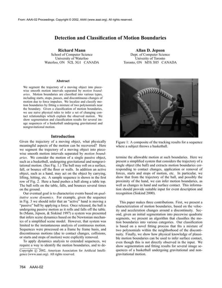
such as a basketball, undergoing gravitational and nongravitational motion. (See Fig. 1.) The ball may roll on a surface,
fall, or bounce off the floor or walls. In addition an active
object, such as a hand, may act on the object by carrying,
lifting, hitting, etc. A sample sequence is shown in the first
row of Fig. 2. Here a hand pushes a ball along a table top.
The ball rolls on the table, falls, and bounces several times
on the ground.
Our eventual goal is to characterize events based on qualitative scene dynamics. For example, given the sequence
in Fig. 3 we should infer that an “active” hand is moving a
“passive” ball by applying a force. Once released, the ball is
undergoing passive motion as it rolls and falls off the table.
In (Mann, Jepson, & Siskind 1997) a system was presented
that infers scene dynamics based on the Newtonian mechanics of a simplified scene model. However, that system was
limited to the instantaneous analysis of continuous motion.
Sequences were processed on a frame by frame basis, and
discontinuous motions (due to contact changes, collisions,
or starts and stops of motion) were explicitly removed.
To apply dynamics analysis to extended sequences, we
require a way to identify the motion boundaries, and to dec 2002, American Association for Artificial IntelliCopyright gence (www.aaai.org). All rights reserved.
764
AAAI-02
Figure 1: A composite of the tracking results for a sequence
where a subject throws a basketball.
termine the allowable motion at such boundaries. Here we
present a simplified system that considers the trajectory of a
single object (the ball) and extracts motion boundaries corresponding to contact changes, application or removal of
forces, starts and stops of motion, etc. In particular, we
show that from the trajectory of the ball, and possibly the
proximity of the hand, we can infer motion boundaries, as
well as changes in hand and surface contact. This information should provide suitable input for event description and
recognition (Siskind 2000).
This paper makes three contributions. First, we present a
characterization of motion boundaries, based on the velocity and acceleration changes around a discontinuity. Second, given an initial segmentation into piecewise quadratic
segments, we present an algorithm that classifies the motion boundaries into various categories. Our classification
is based on a novel fitting process that fits a mixture of
two polynomials within the neighborhood of the discontinuity. Finally, we show how physical knowledge of plausible motion boundaries can be used to infer surface contact,
even though this is not directly observed in the input. We
show segmentation and fitting results for several image sequences of a basketball undergoing gravitational and nongravitational motion.
offtable: 2242
2251
2262
2270
2275
rollhit: 205
220
235
250
265
toss: 1022
1027
1031
1035
1039
Figure 2: Video sequences used for tracking and segmentation experiments. The ball and forearm are modeled by an circle and
an (elongated) octagon, respectively. See text for details.
H
M,C
M,C
G
D2
X(t),Y(t)
0
H
0
M,C
G
G
D10
D10
D10
C
C
C
C
0
0
0
G
G
D10
D10
0
C0
Y(t)
X(t)
2230 2240 2250 2260 2270 2280 2290 2300 2310 2320
frame
Figure 3: Segmentation of the basketball’s motion in the
“offtable” sequence (first row of Fig. 2) into piecewise
smooth motion intervals separated by motion boundaries.
The bar shows frames where the hand and ball overlap in
the image. Intervals are labeled, H: hand contact, G: gravitational motion, M: nongravitational motion. D01 and D02
denote velocity and acceleration discontinuities. C denotes
contact interval, C0 denotes instantaneous contact.
Characterizing motion boundaries
We characterize motion by piecewise smooth intervals separated by boundaries (motion “transitions”) where there are
changes in velocity, acceleration, or contact relations with
other objects.
Motion boundaries are defined by two consecutive open
time intervals separated by an instant t0 . We describe motion
boundaries using a set of fluents (time varying propositions)
P (t). Let P− (t0 ) be the truth value of P (t) on an open
interval immediately preceding t0 and P+ (t0 ) be the value
of P immediately following t0 . P0 is the value of P at the
transition t0 (if it is defined).
The motion transition is an idealized model. For example, during a collision a large force is exerted over a nonvanishing temporal duration while the colliding objects are in
contact. In our model, this will be represented as an instantaneous event, due to limits on the temporal resolution. A
related issue is that, since we measure position only at discrete times, we can never say conclusively whether a motion
discontinuity has occurred. For any sequence of n sample
points, we can always fit the data exactly with a continuous
polynomial of order n − 1. In practice, however, velocity
and acceleration changes can be inferred by fitting low order polynomials to both sides of a discontinuity and looking
for large changes in the slope and/or curvature of the data fit.
We now provide event definitions based on changes of
motion and/or contact fluents at motion boundaries.
Motion transitions
Let p(t) denote the position of the object along a trajectory,
which we assume to be continuous and piecewise differentiable. Let M (t) indicate that the object is moving at time
t. We have M (t) ≡ v(t) = dp(t)/dt 6= 0.1 Let M− (t0 )
denote that the object is moving on an open interval immediately preceding t0 and M+ (t0 ) indicate that the object is
1
Here we consider only the speed of the object. A similar representation may be constructed to describe direction discontinuities.
AAAI-02
765
v(t)
moving immediately after t0 . The conditions are:
v(t)
v(t)
M− (t0 ) ≡ ∃ > 0, s.t. ∀t, t0 − < t < t0 , v(t) 6= 0 (1)
M+ (t0 ) ≡ ∃ > 0, s.t. ∀t, t0 < t < t0 + , v(t) 6= 0 (2)
Note that if the velocity v(t) has a zero crossing at t = t0
we still have M− (t0 ) and M+ (t0 ), but no motion at time
t0 . This corresponds to an (instantaneous) pause at time t0 .2
Finally, we have
M0 (t0 ) ≡ v(t0 ) 6= 0
M − M 0 M+
M− D0 M+
M− M0 M+
pause
discontinuous motion smooth motion
v(t)
v(t)
v(t)
(3)
Let D0n (t0 ), n > 0 denote a discontinuity of order n at
t = t0 . We have:
D0n (t0 ) ≡ lim
t↑t0
dn p(t)
dn p(t)
=
6
lim
t↓t0 dtn
dtn
(4)
D02 and D01 denote acceleration and velocity discontinuities,
respectively. Acceleration discontinuities result from the application or removal of forces (eg., due to contact changes
or starts and stops of motion) while velocity discontinuities
result from force impulses (eg., collisions). We use D0 to
represent a general discontinuity, either in velocity or acceleration. In general, we may have a motion discontinuity of
any order. For example, D03 indicates a discontinuity in the
rate of change of acceleration. Furthermore, several orders
of discontinuity may occur simultaneously, such as when a
force and an impulse are applied to an object simultaneously.
For the purpose of distinguishing collisions and gravitational
and nongravitational motion, however, it is sufficient to consider only first (D01 ) and second (D02 ) order discontinuities.3
In the next section we will use Eqn. (4) to classify motion
boundaries based on the derivatives of low-order polynomials fit to either side of the transition.
Fig. 4 shows the eight possible motion transitions (Jepson & Feldman 1996). The transitions are determined by
combining the motion fluents subject to the following constraints: 1) the trajectory is continuous (but the velocity may
not be); 2) the velocity at a discontinuity is not defined. Note
that of the eight possible transitions, only six of them correspond to motion changes. The remaining two are “nonevents” corresponding to smooth motion and no motion, respectively. We specify the above constraints as follows:
M − M 0 M+
smooth start
v(t)
M− M 0 M +
smooth stop
M − D0 M+
abrupt start
M −M 0M +
rest (no motion)
v(t)
M− D0 M +
abrupt stop
Figure 4: The eight possible motion transitions. M− , M0 ,
M+ denote motion before, at, and after the transition, respectively. M denotes rest (absence of motion). D0 denotes
a velocity discontinuity at the transition. See text for details.
Transition
Event
C− C0 C+
C − C0 C+
C− C0 C +
C − C0 C +
continuous contact
onset of contact
removal of contact
instantaneous contact
Table 1: Consistent contact transitions. C denotes surface
contact. Similar conditions apply for H (hand contact).
Contact transitions
Axiom 2 (Motion value (zeros)) (M − ∨M + )∧D0 ⊃ M 0 .
If there is zero motion on the open interval t < t0 or t > t0 ,
and there is no discontinuity at t0 there must be zero motion
at the boundary t0 .
In addition to motion changes, we consider contact with an
active object, such as a hand, and contact with a surface,
such as a ground plane, a table, or a wall. Let t = t0 be a
place where motion and/or contact changes. H− , H0 , H+
and C− , C0 , C+ denote hand and surface contact, respectively.
Table 1 shows the allowable motion transitions for contact. These are the same as that in Fig. 4 except that since
contact is a spatial variable, it must be piecewise continuous:
Axiom 3 (Motion discontinuities) D0 ⊃ ¬(M − ∧ M + ).
Discontinuities change the motion value (from non-motion
to motion).
Axiom 4 (Continuity of spatial fluents) C− ∨ C+ ⊃ C0 .
Contact in the preceding or following interval implies contact at the transition.4
Axiom 1 (Disjoint motion labels) Exactly one of the labels
in each of the sets {M− , M − }, {M0 , M 0 , D0 }, {M+ , M + }
must hold for the motion before, at, and after the transition.
2
Another type of pause will occur over a nonzero interval. Such
a pause can be decomposed into a “stop” transition at t1 followed
by a “start” at t2 > t1 .
3
(Rubin 1986) observes that humans typically perceive only the
lowest order discontinuity, and that we have trouble distinguishing
second order from higher order discontinuities.
766
AAAI-02
Note that hand and surface contact are not directly observed; they must be inferred from the image information,
and from the motion discontinuities. Hand contact can be
4
C and M correspond to special values (zeros) of fluents. (Galton 1990) refers to these as fluents of position.
inferred from the overlap of the hand and the ball in the image. Surface contact must be inferred from support information and motion changes, such as collisions, and starts and
stops of motion.
Transition
Event
G− → G+
G− D0 C0 G+
G− D0 H0 G+
bounce
hit
Plausible motion boundaries
G− → G+
Using motion boundaries we may describe a wide variety
of natural events. Table 2 shows a partial list of transitions,
along with their typical physical events.
We begin by distinguishing gravitational and nongravitational motions. This gives four possible transitions: G− →
G+ , G− → G+ , G− → G+ , G− → G+ . Transitions of
gravitational motion must satisfy:
G− D0 C0 G+ C+
G− D0 H0 G+ H+
D02 ,
Axiom 5 (Motion value (gravity)) G− ∧ G+ ⊃
G− ∧
2
2
G+ ⊃ D0 , G− ∧ G+ ⊃ D0 . Gravitational motion corresponds to a specific value of acceleration. Acceleration
changes occur iff D02 .
splat
catch
G− → G+
G− C− D0 C0 G+
G− H− D0 H0 G+
launch
drop/throw
G− → G+
G− C− D0 C0 G+ C+
G− C− D0 C0 H0 G+ C+
G− C− H− D0 C0 H0 G+ C+
G− C− D0 C0 H0 G+ C+ H+
bounce (on surface)
hit (on surface)
release (on surface)
catch (on surface)
Within each transition we consider the onset and/or removal of hand and surface contact. We arrive at the events
in Table 2 by considering a few simple constraints based on
our naive physical knowledge of the scene:
Table 2: Some natural events expressed as transitions between gravitational (G) and nongravitational (G) motion.
See text for details.
Constraint 1 (Support) G ⊃ H ∨ C. An object that is
not falling must be “supported”, either by hand or surface
contact.
Temporal consistency
A full determination of support requires an analysis of dynamics (the forces among objects) (Mann, Jepson, & Siskind
1997) and/or the kinematics (allowable motion of objects
under a gravitational field) (Siskind 2000). Here we simply
allow support whenever there is hand or surface contact.
Constraint 2 (Gravitational motion implies no contact)
G ⊃ C ∧ H.
This is the converse of Constraint 1. While it is possible
for falling objects to have contact, eg., against a wall, we
consider such motions unlikely.5
Constraint 3 (Discontinuities require contact)
D0 ⊃ C0 ∨ H0 . Velocity and acceleration discontinuities can only result from surface or hand contact (eg.
hitting, bouncing, etc).
Note that these constraints are very weak. In particular, they allow arbitrary events, such as launching, starting,
stopping, etc. as long as there is a corresponding contact.
Nonetheless, we can infer surface contact over intervals of
nongravitational motion (ie., support by a surface), and at instants where there are velocity discontinuities (ie., collisions
with a surface). Note that these inferences are only valid
when there is no hand contact. In the case of hand contact
we are indifferent about surface contact. We return to this
issue in the Conclusion.
5
See (Jepson, Richards, & Knill 1996) for a discussion of how
to specify possible motion states using qualitative probabilities.
Given two adjacent motion boundaries at time tn and tn+1
we require that: 1) the fluents after tn are consistent with the
fluents before tn+1 ; 2) there are no intervening times where
the fluents change value.
Preference 1 (Consistency of adjacent boundaries)
∀n, P+ (tn ) ≡ P− (tn+1 )
Preference 2 (No unobserved changes within intervals)
∀n, ∀t, t0 , s.t. tn < t, t0 < tn+1 .P (t) ≡ P (t0 )
We write these conditions as preferences, since it is possible that our segmentation algorithm missed some transitions, or that our boundary classification algorithm misclassified some of the motion boundaries. Assuming a segmentation algorithm that finds all motion boundaries, we
can enforce consistency by fitting intervals between adjacent
breakpoints. (See Experiments section.)
Classification of motion boundaries
Suppose we are given a trajectory X(t) = [X(t), Y (t)]T
and a potential transition point t0 . We classify the motion
transition by fitting polynomials to the trajectory immediately before and immediately after t0 . In practice, however,
we may have: 1) poor localization of transitions, 2) trajectory noise, eg., due to tracker error, 3) false breakpoints,
where there is no discontinuity.
We address these problems by fitting a mixture of two
low-order polynomials within a narrow window surrounding the discontinuity. This approach was first used in (Mann
1998) to estimate instantaneous velocity and acceleration
from trajectory data. However, no attempt was made to
detect whether a discontinuity was present. Furthermore,
since there was no constraint on assignments of data points
AAAI-02
767
Experiments
We consider the segmentation of the motion trajectory of an
object, such as a basketball, undergoing gravitational and
nongravitational motion (see Fig. 2). In each sequence the
forearm and the ball were tracked by an adaptive view-based
tracker described in (El-Maraghi In Preparation).
In general, we should apply the model fitting at every
possible breakpoint. Instead, we use a heuristic procedure,
based on dynamic programming, to identify possible breakpoints (Mann, Jepson, & El-Maraghi 2002). The algorithm
separates the trajectory into hand segments (whenever the
hand overlaps the ball in the image), in which the ball may
have arbitrary motion, and piecewise quadratic segments, in
which the ball is under free motion. At each breakpoint we
apply the fitting algorithm described in the previous section
to determine if a motion discontinuity is present, and if so,
to classify the boundary.
Our eventual goal is to find a consistent labeling into motion, hand, and contact fluents. In general this may require
6
We could apply a Bayesian criterion (MacKay 1992), but this
was not necessary here due to the large difference in log likelihood
between the two models.
768
AAAI-02
2 components, initialization
1 component, initialization
250
250
300
300
Y(t)
200
Y(t)
200
350
350
400
400
450
450
1705
1710
1715
frame
1720
1725
1705
1710
1715
frame
(a)
1720
1725
1720
1725
(b)
2 components, final fit
1 component, final fit
250
250
300
300
Y(t)
200
Y(t)
200
350
350
400
400
logL=−112.64
450
1705
450
1710
1715
frame
1720
1725
logL=−227.67
1705
1710
1715
frame
(c)
(d)
Figure 5: Robust mixture model fit at a motion discontinuity. Dotted lines show the temporal support window(s). (a,b)
Initialization for the one and two component models. (c,d)
Final fit for the one and two component models. + and ×
show the ownership for the first and second model, respectively. The squares show the ownership for the outlier process. Note the rejection of noisy track points at frames 1715,
1716 in (c). In (d) many points are rejected as outliers.
2 components
1 component
160
160
180
180
200
200
220
220
X(t)
X(t)
to the two competing polynomials, polynomials sometimes
fit non-contiguous parts of the trajectory.
Here we extend the mixture model by adding a temporal
support window to each component. The data likelihood is
given by:
Qt0 + W2
P (X |θ1 , µt1 , σt1 , θ2 , µt2 , σt2 , σ) = t=t
W
0 − 2 +1
h
π1 N (t; µt1 , σt1 )N (X(t); X̂1 (t; θ1 ), σ)
i
+ π2 N (t; µt2 , σt2 )N (X(t); X̂2 (t; θ2 ), σ) + π0 p0
(5)
X̂1 (t; θ1 ) and X̂2 (t; θ2 ) are the polynomials intended to fit
the left and right portion of the boundary. N (t; µt1 , σt1 ) and
N (t; µt2 , σt2 ) are (Gaussian) windows that weight the data
fit on either side of the transition. π1 and π2 are the mixing
proportions for the two polynomials (π1 + π2 + π0 = 1.). p0
is a (uniform) “outlier” process. σ is the standard deviation
of the tracker noise.
Fig. 5 shows the data fit using quadratic polynomials. The
model was initialized using temporal windows centered at
the left and right side of the proposed boundary. The polynomial coefficients and the temporal support windows were
updated using an EM algorithm. σ began at 16 and was
gradually reduced to 1. A last step was performed to estimate σ from the data. Both X(t) and Y (t) were fit independently, but shared the same mixing proportions and
temporal weighting. To determine whether a discontinuity
is present, we compare the log likelihood of the data with
a model that has only one mixture component. We use a
penalized likelihood criterion (a penalty of −10 in log likelihood for the two component mixture) to decide if a discontinuity is present.6 Penalized likelihood correctly chooses a
two component model when there is a discontinuity (Fig. 5)
and a one component model when there is no discontinuity
(Fig. 6).
240
260
240
260
280
280
300
300
logL=−161.07
320
260
265
270
275
280
frame
(a)
285
290
295
300
logL=−167.34
320
260
265
270
275
280
frame
285
290
295
300
(b)
Figure 6: Robust mixture model fit where there is no discontinuity. (a) Fit with two component model. (b) Fit with one
component model.
top-down information and filling in of undetected or missing breakpoints (DeCoste 1990). Here we assume that the
segmentation algorithm has provided all breakpoints (or a
superset of the breakpoints) for places where the ball is under free motion. We begin with the initial set of breakpoints
and perform a local fit using the mixture model.7 This allows
us to reject spurious breakpoints and to localize the motion
boundaries. Motion boundaries were detected and classified
by using the boundary conditions (velocity and acceleration)
at each interval.8 For intervals that had inconsistent motion
7
We used a classification window of nine samples on either side
of the discontinuity, or the distance to the neighboring transition,
whichever was smaller. To avoid brief contact intervals, we merged
intervals shorter than five samples before processing.
8
The thresholds for discontinuities were ∆V = 5.0 pixels/frame and ∆A = 1.0 pixels/frame2 . An acceleration was con-
X(t),Y(t)
X(t),Y(t)
X(t)
Y(t)
M,C
H
D10
H0
200
M,C
M,C
M,C
1
D10 D0
C0 C0
250
frame
M,C
D0
1
D10 D10
H0,C0
C0 C0
300
M,C
Y(t)
X(t)
H0
350
Figure 7: Segmentation and motion labeling for “rollhit”.
labels (eg. M− and G+ ), we fit a global (quadratic) polynomial to determine the motion type. Surface contact was
inferred whenever there was nongravitational motion on an
interval. Surface contact at transitions was inferred whenever there was either: 1) surface contact at a neighboring
interval, or 2) a velocity discontinuity without the presence
of hand contact.
The classification results for offtable were shown in
Fig. 3. Once the hand segment is removed, we are left with
rolling motion (frames 2241–2263), falling (frames 2264–
2276), and bouncing (frames 2277, etc.). Note the bounce
off the wall (frame 2294). The system correctly infers discontinuities (D02 when falling begins, and D01 at bounces).
Note that, due to tracker errors, there is an extra discontinuity at frame 2246 and that the segment after frame 2293 is
mis-classified (M, C instead of G).
Fig. 7 shows the results for rollhit. Here a hand rolls
the ball against the wall. The ball hits the wall (frame
250), bounces upwards briefly (due to spin), hits the ground
(frame 256), and continues to roll. The hand hits the ball at
frames 307–310. The spurious breakpoint at frame 280 was
removed by the classifier. Note that the small bounces after
frames 250 and 324 are not large enough to be detected as
gravitational motion, therefore the system incorrectly infers
surface contact during these intervals.
Fig 8 shows the results for toss. Here the hand throws the
ball against the wall, and catches it after one bounce on the
floor. Discontinuities are detected at both bounces, and at
the catch.
Conclusion
We showed how to detect and classify motion boundaries
for an object undergoing gravitational and nongravitational
motion.
While successful, there are a number of outstanding issues. First, rather than processing in a bottom-up fashion,
multiple event models should be incorporated into the tracking process (Isard & Blake 1998). Second, since hand contact alone is sufficient to explain nongravitational motion,
we require a more elaborate model of hand motion if we are
1020
1030
D10
C0
1040
H
G
G
G
H
D10
D10
C0
1050 1060
frame
H0
1070
1080
1090
1100
Figure 8: Segmentation and motion labeling for “toss”.
to infer surface contact in intervals containing hand contact.
Finally, we require additional physical constraints on events,
such as forces among objects (Mann, Jepson, & Siskind
1997), energy conservation at collisions, transfer of angular
momentum (eg., spin), etc.
References
DeCoste, D. 1990. Dynamic across-time measurement
interpretation. In Proceedings of AAAI-90.
El-Maraghi, T. F. In Preparation. Robust Online Appearance Models for Visual Tracking. Ph.D. Diss., Dept. of
Computer Science, Univ. of Toronto.
Galton, A. 1990. A critical examination of allen’s theory
of action and time. Artificial Intelligence 42:159–188.
Isard, M., and Blake, A. 1998. A mixed-state condensation
tracker with automatic model-switching. In International
Conference on Computer Vision (ICCV-98).
Jepson, A. D., and Feldman, J. 1996. A biased view of
perceivers. In Knill, D., and Richards, W., eds., Perception
as Bayesian Inference. Cambridge University Press.
Jepson, A. D., Richards, W., and Knill, D. 1996. Modal
structure and reliable inference. In Perception as Bayesian
Inference.
MacKay, D. J. C. 1992. Bayesian interpolation. Neural
Computation 4:415–447.
Mann, R., Jepson, A., and El-Maraghi, T. 2002. Trajectory
segmentation by dynamic programming. In International
Conference on Pattern Recognition (ICPR-02).
Mann, R., Jepson, A., and Siskind, J. M. 1997. The computational perception of scene dynamics. Computer Vision
and Image Understanding 65(2):113–128.
Mann, R. 1998. Computational Perception of Scene Dynamics. Ph.D. Diss., Dept. of Computer Science, Univ. of
Toronto.
Rubin, J. 1986. Categories of Visual Motion. Ph.D. Diss.,
M.I.T. Dept. Brain and Cognitive Sciences.
Siskind, J. M. 2000. Grounding the lexical semantics of
verbs in visual perception using force dynamics and event
logic. Journal of Artificial Intelligence Research 15:31–90.
sidered to be gravitational if A ∈ [1, 2] pixels/frame2
AAAI-02
769

