COOPER POWER
Splices
EZ II Splice
SERIES
15, 25 and 35 kV EZ II splice
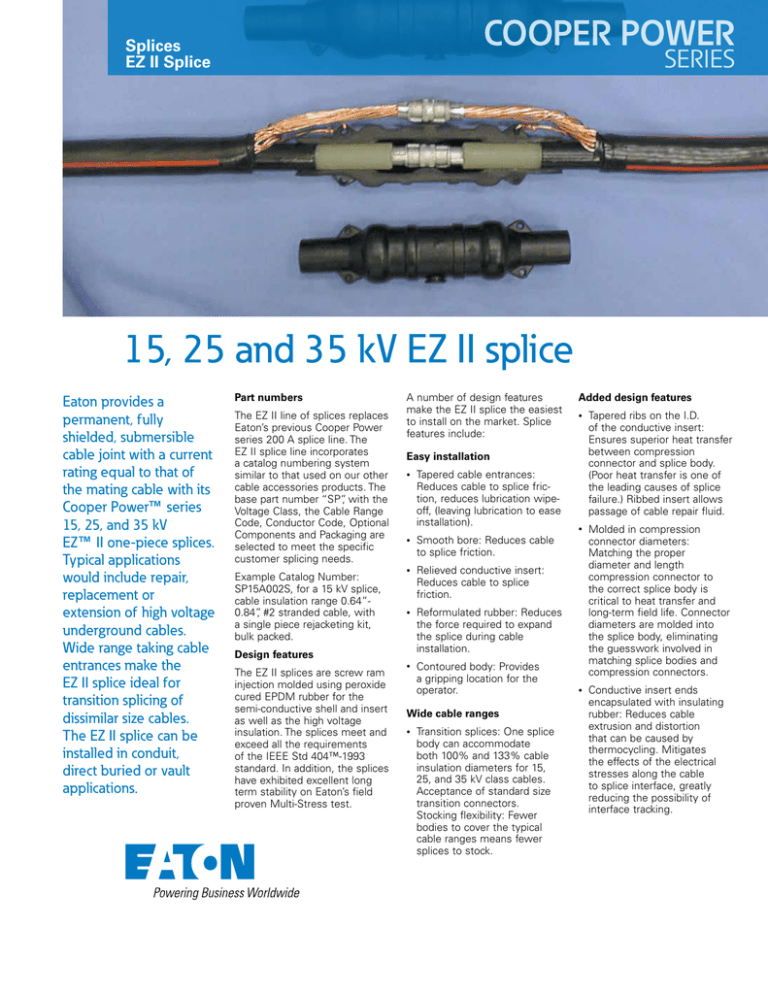
Eaton provides a
permanent, fully
shielded, submersible
cable joint with a current
rating equal to that of
the mating cable with its
Cooper Power™ series
15, 25, and 35 kV
EZ™ II one-piece splices.
Typical applications
would include repair,
replacement or
extension of high voltage
underground cables.
Wide range taking cable
entrances make the
EZ II splice ideal for
transition splicing of
dissimilar size cables.
The EZ II splice can be
installed in conduit,
direct buried or vault
applications.
Part numbers
The EZ II line of splices replaces
Eaton’s previous Cooper Power
series 200 A splice line. The
EZ II splice line incorporates
a catalog numbering system
similar to that used on our other
cable accessories products. The
base part number “SP”, with the
Voltage Class, the Cable Range
Code, Conductor Code, Optional
Components and Packaging are
selected to meet the specific
customer splicing needs.
Example Catalog Number:
SP15A002S, for a 15 kV splice,
cable insulation range 0.64”0.84”, #2 stranded cable, with
a single piece rejacketing kit,
bulk packed.
A number of design features
make the EZ II splice the easiest
to install on the market. Splice
features include:
•
Tapered ribs on the I.D.
of the conductive insert:
Ensures superior heat transfer
between compression
connector and splice body.
(Poor heat transfer is one of
the leading causes of splice
failure.) Ribbed insert allows
passage of cable repair fluid.
•
Molded in compression
connector diameters:
Matching the proper
diameter and length
compression connector to
the correct splice body is
critical to heat transfer and
long-term field life. Connector
diameters are molded into
the splice body, eliminating
the guesswork involved in
matching splice bodies and
compression connectors.
•
Conductive insert ends
encapsulated with insulating
rubber: Reduces cable
extrusion and distortion
that can be caused by
thermocycling. Mitigates
the effects of the electrical
stresses along the cable
to splice interface, greatly
reducing the possibility of
interface tracking.
Easy installation
•
Tapered cable entrances:
Reduces cable to splice friction, reduces lubrication wipeoff, (leaving lubrication to ease
installation).
•
Smooth bore: Reduces cable
to splice friction.
•
Relieved conductive insert:
Reduces cable to splice
friction.
•
Reformulated rubber: Reduces
the force required to expand
the splice during cable
installation.
•
Contoured body: Provides
a gripping location for the
operator.
Design features
The EZ II splices are screw ram
injection molded using peroxide
cured EPDM rubber for the
semi-conductive shell and insert
as well as the high voltage
insulation. The splices meet and
exceed all the requirements
of the IEEE Std 404™-1993
standard. In addition, the splices
have exhibited excellent long
term stability on Eaton’s field
proven Multi-Stress test.
Added design features
Wide cable ranges
•
Transition splices: One splice
body can accommodate
both 100% and 133% cable
insulation diameters for 15,
25, and 35 kV class cables.
Acceptance of standard size
transition connectors.
Stocking flexibility: Fewer
bodies to cover the typical
cable ranges means fewer
splices to stock.
Installation
Specification
The EZ II splices have been
designed to install using typical
cable stripping and crimping
tools found on all line trucks.
Optional two-piece and onepiece cold shrink rejacketing
kits are also available. Flexible
cable entrances increase the
visibility of the ends of the
cable insulation shield, allowing
foolproof centering of the splice.
To ensure you have the most
reliable, installation friendly,
economical, one-piece
splice available, your splice
specification should include:
GROUNDING TAB
G rounding tabs
provide points to
connect a ground
wire to maintain the
molded outer
shield at ground
potential.
•
Manufactured in full
compliance with all applicable
IEEE Std 404™-1993 and IEEE
Std 592™-2007 standards
•
Manufactured from peroxide
cured EPDM rubber
•
Ground shield molded on
•
Wide range taking cable
entrances
•
Compression connector
diameter molded into splice
body
•
Ribbed conductive insert
•
Encapsulated ends of the
conductive insert
MOLDED CONDUCTIVE INSERT
Molded peroxide cured semi-conductive
insert provides corona-free electrostatic
shielding of the air surrounding the
compression connector.
INSULA TION
Encapsulates ends of
semicon insert reducing voltage stre s s .
TAPERED RIBS
Peroxide cured semi-conductive
insert ensures superior contact
with the connector and allows for
passage of cable repair fluids.
C ONTOURED BODY
Provides improved
grip.
MOLDED IN SUFFIX
LETTER AND CABLE
RANGE
MOLDED IN
CONNECTOR DIAMETER
EPDM RUBBER INSULATION
Molded peroxide cured EPDM
insulation provides line to ground
insulation and a watertight seal.
MOLDED OUTER SHIELD
Molded semi-conductive
outer shield of peroxide
cured EPDM rubber provides
a protective,uniform ground
shield.
Eaton
1000 Eaton Boulevard
Cleveland, OH 44122
United States
Eaton.com
Eaton's Cooper Power Systems Division
2300 Badger Drive
Waukesha, WI 53188
United States
Cooperpower.com
© 2015 Eaton
All Rights Reserved
Printed in USA
Publication No. PA650004EN
Supersedes 99045
March 2015
FLEXIBLE CABLE ENTRANCE
Provides for a larger cable range
and easier installation.
For Eaton's Cooper Power series
product information,
call 1-877-277-4636 or
visit: www.CooperPower.com
Eaton, Cooper Power, and EZ are valuable
trademarks of Eaton in the U.S. and other
countries. You are not permitted to use these
trademarks without the prior written consent
of Eaton.
IEEE Std 404™-1993 and IEEE Std 592™2007 standards are trademarks of the Institute
of Electrical and Electronics Engineers,
Inc., (IEEE). This publication/product is not
endorsed or approved by the IEEE.
Follow us on social media to get the
latest product and support information.


