From: AAAI-90 Proceedings. Copyright ©1990, AAAI (www.aaai.org). All rights reserved.
Interaction-based
Invention:
evices from First Principles
esigning Novel
Brian 6. Williams*
System Sciences Laboratory
Xerox Palo Alto Research Center
3333 Coyote Hill Road, Palo Alto CA 94304
bwilliams@xerox.com
Abstract
An inventor who is skilled at constructing
innovative
designs is distinguished,
not just by the first principles
he knows, but by the way he uses these principles and
how he focusses the search for novel devices among an
overwhelming
space of possibilities.
We propose that an
appropriate
focus for design is the network of qualitative
interactions
between quantities,
(called an interaction
topology), used by a device to achieve its desired behavior. We present an approach,
called interaction-based
invention, which views design as a process of building interaction
topologies - in this paper directly from
first principles.
The program fiis, which embodies this
approach,
designs simple hydro-mechanical
regulators,
analogous to devices that were fundamental
to the development of feedback control theory.
1
Innovation is a multi-faceted process that researchers
are only beginning to explore [Murthy & Addanki 1987;
Ulrich 1988; Joskowicz & Addanki 19891. This paper explores one such facet - the process of innovation when
reasoning from first principles alone. Specifically we
present a theory that captures key aspects of a process
that can be used to construct novel devices like the one
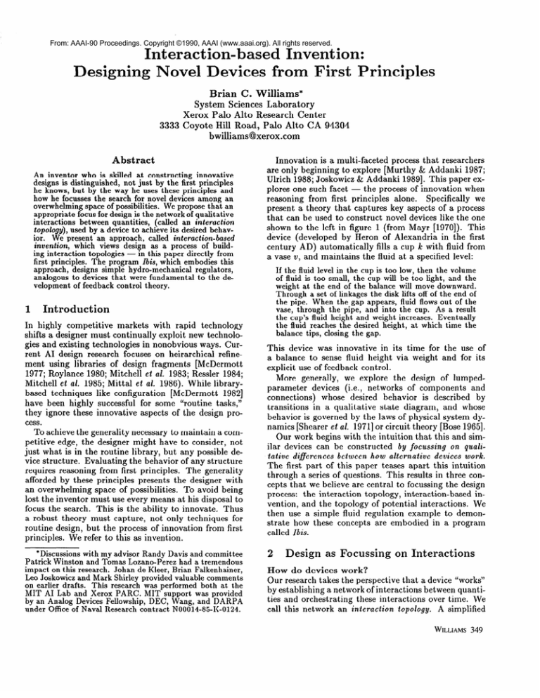
shown to the left in figure 1 (from Mayr [1970]). This
device (developed by Heron of Alexandria in the first
century AD) automatically fills a cup k: with fluid from
a vase V, and maintains the fluid at a specified level:
If the fluid level in the cup is too low, then the volume
of fluid is too small, the cup will be too light, and the
weight at the end of the balance will move downward.
Through a set of linkages the disk lifts off of the end of
the pipe. When the gap appears, fluid flows out of the
vase, through the pipe, and into the cup. As a result
the cup’s fluid height and weight increases.
Eventually
the fluid reaches the desired height, at which time the
balance tips, closing the gap.
Introduction
In highly competitive markets with rapid technology
shifts a designer must continually exploit new technologies and existing technologies in nonobvious ways. Current AI design research focuses on heirarchical refinement using libraries of design fragments [McDermott
1977; Roylance 1980; Mitchell et al. 1983; Ressler 1984;
Mitchell et al. 1985; Mittal et al. 1986). While librarybased techniques like configuration [McDermott 19821
have been highly successful for some “routine tasks,”
they ignore these innovative aspects of the design process.
To achieve the generality necessary to maintain a competitive edge, the designer might have to consider, not
just what is in the routine library, but any possible device structure. Evaluating the behavior of any structure
requires reasoning from first principles. The generality
afforded by these principles presents the designer with
an overwhelming space of possibilities. To avoid being
lost the inventor must use every means at his disposal to
focus the search. This is the ability to innovate. Thus
a robust theory must capture, not only techniques for
routine design, but the process of innovation from first
principles. We refer to this as invention.
*Discussions with my advisor Randy Davis and committee
Patrick Winston and Tomas Lozano-Perez
had a tremendous
impact on this research.
Johan de Kleer, Brian Falkenhainer,
Leo Joskowicz and Mark Shirley provided valuable comments
on earlier drafts.
This research was performed
both at the
MIT AI Lab and Xerox PARC. MIT support was provided
by an Analog Devices Fellowship, DEC, Wang, and DARPA
under Office of Naval Research contract
N00014-85-K-0124.
This device was innovative in its time for the use of
a balance to sense fluid height via weight and for its
explicit use of feedback control.
More generally, we explore the design of lumpedparameter devices (i.e., networks
of components
and
connections) whose desired behavior is described by
transitions in a qualitative state diagram, and whose
behavior is governed by the laws of physical system dynamics [Shearer et al. 19711or circuit theory [Bose 19651.
Our work begins with the intuition that this and similar devices can be constructed by focussing on qualitative diflerences
between how alternative
devices
work.
The first part of this paper teases apart this intuition
through a series of questions. This results in three concepts that we believe are central to focussing the design
process: the interaction topology, interaction-based invention, and the topology of potential interactions. We
then use a simple fluid regulation example to demonstrate how these concepts are embodied in a program
called Ibis.
2
Design
as Focussing
How do devices
on Interactions
work?
Our research takes the perspective that a device “works”
by establishing a network of interactions between quantities
and
orchestrating
these
interactions
call this network an interaction
topology.
over
time.
We
A simplified
WILLIAMS 349
are identified using the first principles of the current
domain and technology, and interactions are interconnected through shared variables. The topology is verified
by algebraically “composing” interactions and comparing the result with the desired interaction.
A strategy for proposing the interconnection of interactions is faced with an enormous space of possibilities.
To cope, Ibis generates candidate solutions by focussing
first on the most constraining features of interactions . . .
I
Q’
/-\
CUP
Figure 1: Heron’s weight regulator from [Mayr 19701
(left) and interaction-based invention (right). The graph
at the upper right is an interaction topology, constructed
to relate dHjluia/dt
to Hfluid and H&s&d. The topology is built from interactions, each producible by a single
component or connection (downward arrows).
example for Heron’s regulator1 is depicted by the graph
in figure 1 (top right), where H, M, Q and V denote
fluid height, mass, flow and volume. The explanation
in the introduction traced a path through this topology.
In addition to connectivity, the topology must capture
exactly those features of interactions that directly contribute to how a device achieves its behavioral specification. Initially a designer ignores many details of the
specification like delay and power dissipation, instead
focussing on the basic shape of a device’s behavior. In
our case this is the rise and fall of fluid levels or, more
generally, state transitions in a qualitative state diagram
[Bobrow (ed.) 19841. Th e salient features of interactions
are exactly those necessary to achieve each transition. In
[Williams 1988, 19891 we argue that this is captured by
a combination of qualitative and quantitative features,
expressible by equations in Ql - a hybrid algebra on
signs and reals.2
How do these observations
impact
invent ion?
We claim that, because the interaction topology captures qualitative features of how devices work, it is an
appropriate central focus of invention. Specifically:
Invention
involves constructing
a topology
of interactions that both produces
the desired behavior
and
makes evident a topology of physical devices that implements those interactions
(figure 1, right).
This approach, called Interaction-bused
Invention, has
three major components: building the interaction topology, building the corresponding physical structure, and
verifying that the interactions produce the desired behavior. To ensure that the topology “makes evident”
the physical structure, the topology is built from interactions that are producible by & single component
or physical connection.
The producible interactions
example of an interaction
topol‘A more rep resentative
ogy is shown in figure 5.
2 For more complex topologies, in [Williams 19891we argue
for the importance
of capturing
an interaction’s
causal and
temporal features at a level of abstraction
expressible in the
representations
of [Williams 1984, 1986].
350 COMMONSENSEREASONING
What
qualitative
features
are most
important?
Rarely do primitives directly relate the types of variables were interested in. For example, the purpose of
Heron’s regulator is to relate height change to height
difference, but there is no way to achieve this directly.
Instead the device uses a lengthy chain of interactions
that successively transform a signal from one variable
type to another. This difficulty is highlighted by the
connectivity
of interactions,
conveyed in the graph of
figure 1 (top right), independent of the behavior each
interaction produces. The importance of connectivity is
further supported by a detailed historical analysis [Mayr
19701 which uses similar diagrams to highlight the innovative aspects of feedback control devices developed over
a period of 1800 years. For example, Heron’s innovation
is a path of interactions that uses force to sense height.
The end of this paper shows several other innovations
that exploit alternative paths. To summarize, qualitative features that are particularly important are the
connectivity of interactions and the types of variables
involved.
How are devices
composed
from first principles?
We coniecture that, for simple devices, new innovations
are constructed in a manner similar to how existing inventions are understood. To understand how a device
works, we first imagine all the interactions produced by
every component and every connection in the device,
and then trace out a path that identifies interactions
contributing to the behavior of interest. Analogously, to
invent a device, we use our first principles to imagine all
possible interactions producible by every type of component and every type of connection available in the current technology, and all ways that these interactions can
be connected. The resulting structure we call a topology
of potential interactions.
A device is proposed by tracing a path through the potential interaction topology
that connects variables in the desired interaction. The
device’s interaction topology are those variables and interactions that lie along the path. We call this process imagining
potential
interactions.
Interesting
alter-
natives correspond to distinct paths through this topology. Of course it would be unreasonable to explicitly
represent all producible interactions and interconnections, since the space would be infinite. Compactness
is achieved by representing types rather than instances.
The topology of potential interactions is built from the
types of interactions producible, connected wherever it
is consistent for them to share a variable. These interaction types are those produced by each type of component
and physical connection.
To maximize function sharing - the use of a single
component for several functions - it is important wherever possible to exploit interactions produced by existing structure (structure already introduced in the design). This helps to reduce design costs and parasitic
effects. In some cases variables in a desired interaction
are only accessible through existing interactions - function sharing is then an absolute necessity. To this end
we augment our space with a topology of existing interactions, representing the interactions of a partially constructed design, that are produced by structure already
introduced. This is interconnected with the topology of
potential interactions wherever it is consistent to share
variables. A candidate solution is proposed by tracing a
path through the combined topology, for example, minimizing the number of potential interactions traversed
(figure 2, top of upper half).
This combined topology is the key to our approach.
It is an interaction topology and thus focuses the search
within the realm of how devices work. It makes physical structure evident - each interaction is produced by
a type of component or connection. It can be searched
quickly - path tracing in a small graph is fast. It captures the first principles - that’s what the topology
is built from. And it highlights connectivity between
variable types - one of the most constraining, and potentially innovative aspects of alternative solutions. Together these features allow us to make good on the claim
that we are able to construct innovative devices from
first principles.
3
Ibis:
Interaction-based
Invention
System
For simplicity of presentation we demonstrate our approach using the punch bowl example of [Williams 19881
(e.g., as opposed to heron’s regulator):
Suppose you are throwing a large party that includes
beverages.
Havine waiters manuallv
refill the nunch
bowl f;om a 1arge”vat would intrude on the ambiance
of the event; thus, you decide to use Ibis to construct
a
device that restores the punch bowl automatically.
At
Ibis’ disposal is an array of pipes, containers
and lids.
The vat, V, and bowl, b, are sitting on a table, both
the vat is hidden, and
open to the air. For aesthetics
connections
are only allowed to the bottom of the vat
and bowl. For simplicity you decide the level of punch
in the bowl should be the same as that in the vat.
The desired behavior is specified by a qualitative state
diagram. Using a process roughly analogous to finite
state machine design [II:Jl & Peterson 19’?4], Ibis maps
the diagram into interactions. As discussed in [Williams
19891, in our example Ibis infers that the desired interaction is to change the bowl’s iiuid height in the direction
of the vat/bowl height difference (i ] denotes an espression’s sign {+, 0, -)):
Our focus here is on how Ibis maps a single desired interaction into an interaction topology. Ibis’ basic steps
are numbered on the top half of figure 2. First, Ibis
BI JILD:
PHYSICAL
REFINE:
POTENTIAL
INTERACTIONS
STRUCTURE
POTENTIAL
INTERACTIONS
Figure 2: Major steps Ibis performs to build (upper) and
refine (lower) an interaction topology.
builds the space of all interactions: the topology of potential interactions for the domain and technology, and
the topology of existing interactions for the initial structure and interactions. Second, Ibis proposes a candidate
by identifying a path through the two topologies, connecting the variables in the desired interaction. Third,
Ibis augments the device structure in order to instantiate
the potential interactions along the path (and links connecting these interactions). Finally, Ibis verifies that the
path produces the behavior of the desired interaction.
Ibis may fail on two accounts: either because the
structure introduced in the third step is inconsistent,
or because the behavior verified in the fourth step is incorrect. In either case Ibis ha.. the choice of exploring a
topology corresponding to an alternative path, or refining the current candidate (bottom half, figure 2). In the
latter case Ibis A) identifies one or more links causing
inconsistencies, B) breaks these links to remove all inconsistencies, (preserving the consistent links and interactions), and C) tries to close the gaps where these links
have been broken, by tracing additional paths through
the topology of potential interactions. Finally, Ibis repeats the process of introducing structure and verifying
behavior (steps 3 and 4).
To support this process, Ibis exploits two reasoning
components described elsewhere: the symbolic algebra
system, called Minima, for the hybrid qualitative quantitative algebra Ql [Williams 19881, and the hybrid terminological reasoning and congruence closure system called
WILLIAMS 35 1
vat(v);
bowl(b);
PipeW);
node(N1);
node(N2);
Iota [Williams 19891. Th e remaining sections describe
Ibis’ inputs and demonstrate the first four steps of the
building process on our example. Refinement is demonstrated in [Williams 19891.
4
Ibis’ Inputs
and Outputs
Ibis takes as input the desired interaction, initial constraints on the physical structure and interactions, and
terminological definitions and physical principles characterizing the domain and technology. It produces from
these a consistent physical structure whose interaction
topology produces the desired interaction. First consider inputs involving structure. The terminological definitions describe the classes of valid physical structures
(e.g., pipes, containers), quantities (e.g., H, P) and their
interrelationships for a given domain and technology.
The initial and final structures describe particular instances of these classes (called individuals) and their interrelationship. Each is described in a terminological
language, called Iota, roughly similar in style to languages like Klone [Brachman & Schmolze 19851. Iota’s
syntax and semantics is presented in [Williams 19891.
Our example uses a device-centered model. That is,
each component communicates externally through a set
of terminals, and a physical structure is a network of
components whose terminals are connected to common
points called nodes. Two example definitions are shown
below, the left is for nodes and the right is for pipes:
node areunique constituent;
tl-of(node) are terminal;
ta-of(node) are terminal;
P(node) are pressure;
1-lfunction(tl-lof);
1-lfunction(t2af);
l-l-function(P);
tl-of(node) disjoint t2-of(node);
forall (n) node(n) implies ntl-of(n)
forall (n) node(n) implies nt2af(n)
pipe are-unique device;
tl(pipe) are-unique terminal;
t2(pipe) are-unique terminal;
R(pipe) are fluid-resistance;
1-lfunction(t1);
1-lfunction(t2);
l-l-function(R);
3 n;
z n;
The left says roughly that a node is a unique type of
physical constituent, and each node has a unique P, tl-of
and t2,of, where P is a pressure, and tl-of and t2-of are
distinct terminals. Also, a terminal which is the tl,of or
t2-of some node has that node associated with it.3 The
right definition says roughly that a pipe is a unique type
of device, and has a unique R, tl and t2, where R is a
fluid resistance, and tl, t2 are distinct terminals. See
[Williams 19891 for the complete set of definitions and
their semantics.
A structural description specifies the individuals that
a device is composed of, their types, and their interrelationship through equivalences (E) and inequivalences
(f). For example, the following describes a solution to
the punch bowl problem that connects a pipe between
the vat and bowl. The corresponding schematic uses
open circles to denote terminals, and closed circles to
denote nodes:
3nT is an abbreviation
minal. We also abbreviate
352
b(v) 3 tLof(N1);
t2-of(N1) z tl(P1);
t2(Pl) E t2,of(N2);
tLof(N2) E b(b);
for node-of T , where T is a terbottom wit ill and top with t.
COMMONSENSEREASONING
The description introduces a distinct vat v, bowl b, pipe
Pl, and two nodes Nl and N2. A component is connected to a node by sharing a terminal. For example,
“b(v) G tl-of(N1)” says that the terminal at the bottom
of v is one of Nl’s terminals. The above description says
that the bottom of v is connected to the tl end of Pl
through node Nl, and the t2 end of Pl is connected
to the bottom of b through node N2. The declarations
“vat(v)” and “bowl(b)” specify the initial structure for
our example.
Next consider the inputs that are specified as interactions: the initial and desired interactions, and physical
principles. An interaction is a qualitative (or quantita
tive) relationship between variables. In this paper it is
an equation in the Ql algebra [Williams 19881. Initial
interactions specify interactions enforced by the problem
statement. In our example, no fluid can flow into the top
of the bowl; that is, &(t(b)) = 0. Desired interactions are
interactions that the design must satisfy - in our example [H(v) - H(b)] = [dH(b)/dt]. The physical principles
describe the types of interactions (called potential interactions) producible by classes of physical constituents.
In a device-centered approach these are interactions produced by classes of components (the device models) and
connections (the connection laws). A potential interaction is an interaction over classes of variables (called
variable types). It is expressed as a universally quantified horn clause. The antecedents restrict each quantifier
to range over defined classes. The consequent is an interaction (here a &I equation) on variables and variable
types (terms containing quantifiers). For example, the
pipe model consists of three potential interactions:
forall (pi) pipe(pi) implies Q(tl(pi)) + Q(t2(pi)) = 0;
forall (pi) pipe(pi) implies Pd(ntl(pi),nta(pi))
= R(pi) x Q(tl(pi));
forall (pi) pipe(pi) implies R(pi) = [+]
The first says that what flows into one end of the pipe
flows out the other end. The second relates a pipe’s
pressure difference (Pd) to its fluid resistance (R) and
flow (Q). The third says that R is always positive.
5
Building
the Space of Interactions
Recall that the topology of potential interactions represents all producible interactions and all ways they interconnect. The topology of existing interactions represents interactions produced by the current structure
and is updated as the structure is modified. To build
the first topology, Ibis creates an undirected hyper-edge
for each potential interaction that connects the interaction’s variables. For example, consider two interactions
t(oc)) -
Patm
Open Container Model: ot
-4
I
P(nl)
Compatibil~~ \
Las
Container Model: c
I
V
,Pd(nl.n2~-
Pd(nt(c),nb(c))
I
-r
I
I
/
dV(c)/dr
NOWd
I
0
dV(ne)/dt
Q(bbc))
I
Size
cmltaincr: nc
-I-
dH(v)/dt
dV(v)/dt
/at
A(4
-
-
o
I+1
Figure 3: The topology of potential (left) and existing (right) interactions for the punch bowl problem. Thick lines
denote interactions and thin lines denote links. Dashed lines show a path through the two topologies between desired
variables: H(v), H(b) and dH(b)/dt. Boxed variables indicate where branches of the path jump between topologies.
- the first is from the pipe model and the second is
the continuity law for nodes (Pd is pressure difference,
Q flow and R resistance):
forall (pi) pipe(pi) implies Pd(ntl(pi),nta(pi))
= Q(tl(pi))
forall (n) node(n) implies Q(tl-of(n))
= - Q(t2-of(n))
x
R(pi);
Hyper-edges representing these two interactions are
shown below by thick lines to the far left and right:
Pd(ntl(pi).
R(pi)
L
nt2(pi))
W
m(pi)) -
QbJfbl)l
-
Qwu44)
Each edge tells us which quantities interact directly,
while suppressing the algebraic properties of the interaction. The complete set of hyper-edges for the example
are shown as thick lines in figure 3, left half.
Next the hyper-edges are combined into a graph. Interactions communicate through shared variables. Possible sharings are represented by thin lines, called links,
between pairs of unifiable variables (i.e., variable types
that aren’t necessarily disjoint and thus can share an
individual). Unification is semantic rather than syntactic, and is determined by Iota from the terminological
definitions. The pipe and continuity interactions shown
earlier are connected by two links. For example, variable
types Q(tl(pi)) and Q(tl-of(n))
are linked - by definition Q is a l-l function; thus, for an individual Q(i) to be
an instance of both variable types, i must be an instance
of both tl(pi) and tl-of(n). This is consistent with the
definitions for pipe and node given earlier. In contrast
Q(tl-of(n)) and Q(t2-of(n)) are not linked, since from
the definition of node tl-of(n) and t2_of(n) are disjoint.
The complete set of links are shown in figure 3, left half.4
*This topology is overly simple for presentation purposes.
Next the topology of existing interactions is constructed, corresponding to the initial structure. This
involves instantiating the applicable potential interactions and combining them with the initial interactions.
Common vertices denote shared variables, where sharing is determined by Iota through congruence closure.
Links are added to this topology between variables that
are unifiable (and not already equivalent). The complete topology of existing interactions for the punch bowl
problem is shown on the right side of figure 3. The vat’s
interactions are to the left and the bowl’s are to the
right.
Once the topology of potential and existing interactions are created, they are interconnected by linking each
variable and variable type that are unifiable. Variables
of interest that link the two topologies are highlighted
in figure 3 by boxes.
6
Proposing
a Candidate
Topology
Next, Ibis uses these topologies to identify a candidate
solution - an interaction topology that has a simple
mapping to physical structure and which may combine
to produce a desired interaction (step two of figure 2).
A candidate solution is a minimal set of interactions and
links that relates those and only those variables in the desired interaction (called desired variables). In our example these variables are H(v), H(b) and dH(b)/dt. A candidate C is identified by tracing a (multi) path between
the desired variable through both interaction topologies.
C consists of every interaction and link touched by the
A more representative topology, for example, combining
hydraulic
and mechanical
properties
might
types of connections
and a few dozen device
contain
types.
several
WILLIAMS 353
INTERACT10
PbW))
p(N1)T
p(Na)
W(b))
Pd(NlJ2)
Pd(nll(Pl),nl2(Pl))
I+L
EXISTING
INTERACTIONS
I
QWfWN
R(Pl
Wl(Pl)kr,
QWPlN
EXISTING
INTERACTIONS
Figure 4: Instantiating the candidate potential interactions (left) and links (right). On the left, a downward arrow
points to the structure and existing interaction that result from instantiating a potential interaction. On the right
each points to the unifications of structure and variables resulting from instantiating a link.
multi path. To relate the desired variables, C should
contain a path P going between the variables that has
no intervening constants. To relate only the desired variables, every branch off of P should terminate on a constant, unless it leads to a desired variable. Intuitively,
a branch terminating on another variable represents an
undesired influence (see [Williams 19891 for details).
A path corresponding to a candidate for the punch
bowl problem are shown as dashed lines in figure 3. It
begins as three separate paths starting at the desired
variables, H(v), H(b) and dH(b)/dt,
and tracing out
through the topology of existing interactions (right half,
figure 3). One branch of each path reaches P(nb(v)),
respectively, which are linked to
P(nb(b)) and Q(W)),
the potential interaction topology. The other branches
terminate on constants (denoted by paths ending with
black dots). After crossing links at P(nb(v)), P(nb(b))
and Q(b(b)), the paths trace through the potential interaction topology, where they come together as a single
path (left half, figure 3). In so doing the path traverses
five links and five potential interactions: the three interactions of the pipe model, and one each for the continuity and compatibility laws (governing the behavior of
connections at nodes) .5
5Note that a single path introduces a component of each
type at most once. Several instances of the same type are introduced either during the refinement process (figure 2, bottom), or when multiple desired interactions are specified.
354 COMMONSENSEREASONING
7
Adding
Interactions
and Structure
Next Ibis augments the topology of existing interactions
with the potential interactions and links in the candidate (step three of figure 2). Potential interactions and
links *are-introduced -through analogous operations on
physical structure. Interactions are instantiated by introducing physical parts (e.g., pipes, nodes, terminals)
- the parts specified in the first principles corresponding to each potential interaction. Links are instantiated
by unifying physical parts. This in turn unifies existing
variables, thereby connecting the interactions together.
The top left of figure 4 shows the candidate potential
interactions and links for our example. Next to each
interaction is the name of the corresponding model or
law. The vat v and bowl b in the middle left of the figure
are part of the initial structure. P(nb(v)), P(nb(b)) and
Q(b(b)) at the bottom left are variables of the existing
interactions that the augmentations connect to.
Ibis instantiates five potential interactions: the interaction from the compatibility law, three interactions
from the pipe model, and the interaction from the continuity law.- First, the compatibility law:
forall (nl,n2) node(n1) and node(n2) implies
Pd(nl,n2) = P(n1) - P(n2)
applies to any pair of nodes; thus, Ibis instantiates the
law by introducing two nodes with unique names - call
them Nl and N2. Similarly, introducing Nl and N2 results in a single interaction being added to the topology
of existing interactions, as is shown by the downward
arrow at the far left of figure 4. The remaining four
interactions are introduced in a similar manner, as depicted in the figure: a pipe Pl for the three interactions
of the pipe model, and a node N3 for the continuity law.
detailed examples). Several refinements are normally
required for complex structures, like Heron’s regulator
and the fluid regulators at the end of this paper.
PbW)
8
02
dH(b)/dt
t+b
0
A(b)
1
dV(b)/dt
A-
Q@oW
Q(WW
OLD INTERACTIONS
.
.
NEW
.
.
.
.
.
.
.
INTERACTIONS
.
.
. .
.
P(N
(r;2).
Pd(
1,N:
.
.
.
.
.
.
.
.
I
Q(tLof(N3))
1
the Desired
Interaction
The remaining step is to determine whether or not the
combined behaviors of the interactions in the candidate produce the desired interaction [H(v) - H(b)] =
[cZH(b)/dt].
Th e composition process involves qualita
tive symbolic algebra on Ql equations, and is performed
by Minima [Williams 19881. To compose interactions,
Ibis starts with the expression involving the variable
being controlled, in our example [dH(b)/cZt].
It walks
back along the path traced when constructing a candidate, accumulating a symbolic expression. Ibis then
tests whether the accumulated expression matches the
other expression in the desired behavior, [H(v) - H(b)].
The sequence of interactions walked through during the
accumulation are numbered in figure 5, with the corresponding expressions at each step shown below. The
initial and final expressions (lines 0, 17) match the desired interaction; thus, connecting the pipe solves the
punch bowl problem.
WWV~~I
0)
W’(b)ldtl@ [-+)I
1)
W@YW
2)
[Q(W)) + Q(m(b))l
3)
[Q(W))1
4)
5)
6)
7)
Figure 5: The augmented topology of interactions.
Numbers indicate the sequence in which interactions are
combined during verification.
Next, to complete the interaction topology Ibis
“glues” the interactions together by instantiating the
candidate links. This involves unifying the variables
of interactions and is accomplished by unifying pieces
of device structure. For example, consider the link between Q(tl-of(n)) and Q(b(b)), shown in the upper right
corner of figure 4. To instantiate this link we want to
equate Q(tLof(N3)) and Q(b(b)). To enforce this equivalence the bottom of bowl b must be connected to N3.
That is, tLof(N3) and b(b) must refer to the same terminal, and N3 and rib(b)) must refer to the same node.
This is inferred by Iota through congruence closure from
the definitions and structural description. The remaining four links are instantiated in a similar manner. The
resulting unifications of structure and variables are depicted by downward arrows in the right half of figure 4.
The net effect of the instantiations is to connect the nine
between the vat and bowl. The augmented interaction
topology is shown in figure 5.
Although the above-structure is consistent with the
definitions, this is not always the case. The reason is that
the topology of potential interactions ensures only that
the links are pairwise consistent - the instances of several links may be globally inconsistent. When this happens the inconsistent links are broken, and the solution
is refined as sketched earlier ([Williams 19891 provides
Verifying
8)
e[w2-ofw3))1
tQ(tl(Pl))l
[Pd(ntl(Pl),nt%(P1))1~
[R(Pl)l
[Pd(ratl(Pl),
rata(m))]
[P(Nl)-JYWl
- P(nt(v)))
- P(Wl
10) KP4Nv), nb(u))
9)
11)
[Pd(rat(v), nb(v)) + P(nt(b))
13)
[Pd(nt(v),
14)
15)
P(u)l(d
12) [Pd(nl(u), nb(v>) + P(n+))
- P(nt(u))
- Pd(nt(b), nb(b))]
- Pain, - Pd(rd(b),d(b))]
nb(u)) - Pd(nt(b), tab(b))]
x 9) - P4~t(b),nW))l
[H(v) - Wb)l Q M 63 [sl
16) [H(v) - H(b)] @J PI
17) [H(u) - WI1
Note that the resulting design is quite compact in part
because the device exploits a substantial set of interactions produced by the initial structure. The complete
set of interactions directly contributing to the desired
behavior is extensive - all those shown in figure 5. Ibis’
use of the topology of existing interactions when proposing candidates is central to how it achieves this type of
function sharing. 6
9
Discussion
Consider briefly the complexity and completeness of
our approach. A simple mapping exists between propositional formulas and Ql equations; thus, verifying an
interaction topology is at least as difficult as S-Sat, and
is in fact NP-hard. Design introduces bounded quantification into the equations (the potential interactions),
raising the problem to first order satisfiability. It is at
61n [Ulrich 19881 a device is initially designed without
function sharing, and then functions are later collapsed.
In
contrast,
for problems like our example, some function sharing must be considered
immediately,
since a solution can
only control the desired variables through existing interactions (e.g., H through P).
WILLIAMS 355
SbeK
Figure 6: Analogues to early feedback devices, constructed by Ibis.
best semi-decidable. Our aspiration then has been to
make the individual steps of interaction-based invention
efficient and to develop a more sophisticated coordination of these steps through future research. Building the
space of interactions, identifying a candidate path, elaborating structure, and testing consistency are at worst
quadratic in the number of individuals and classes introduced. We are working on proving whether Ibis generates all candidates; the other steps are complete. As
discussed above, the verification step is NP-hard. The
set of compositions is linear in the number of interactions, but the cost is in canonicalization and factoring.
As argued in [Williams 19881 Ql has a number of unique
properties that tend to make these operations efficient
in practice. Verification is sound but incomplete. Ibis
has been demonstrated on several simple devices. Also,
it has been walked through the design and verification of
the devices in figure 6, which are analogous to regulators
that were fundamental to the development of feedback
control theory [Mayr 19701. Although we haven’t experimented with this, Ibis should also work with analog
designs, since quantitative equations are a subset of Ql.
Ibis’ initial focus on the connectivity of interactions
bares a loose similarity to Ulrich’s [1988] use of bond
graphs (i.e., graphic depictions of n ports). However
Ulrich’s approach is very different. Bond graphs are
initially proposed by arbitrarily composing bonds, device behavior, excepting connectivity, is never considered, and there are no analogues to Ibis’ topologies of
existing and potential interactions, Ql, Iota or Minima.
The approach of imagining potential interactions is
one piece of a larger project on interaction-based design (see [Williams 19901). We are currently exploring
a more robust causal-temporal representation of interactions and are embedding our approach within evolutionary and library-based design. In addition [Joskowicz
& Addanki 19891 is suggestive of a promising avenue for
combining interaction-based and geometric design.
This work is best summarized by the initial intuition
and series of questions raised in the introduction - innovative devices can be constructed by focussing on qualitative diflerences between how alternative devices work:
How do devices work? By constructing an inter-
action topology and orchestrating it over time.
How does this impact invention?
Invention involves constructing a topology of interactions that both
produces the desired behavior and makes evident a physical structure that implements those interactions.
What
356
qualitative
features
COMMONSENSEREASONING
are most important?
The connectivity of interactions and their variable types.
How are simple devices composed
out of first
rinciples?
By tracing paths through a topology of
potential interactions.
0
References
Bobrow, D. G. (Ed.) [1984],
“Special
Issue
Artificial
Intelligence,
24.
Reasoning,”
on
Qualitative
Bose, A. G., and K. N. Stevens [1965],
Iratrodz~tor-y
Network
Theory, Harper and Row, New York.
Brachman,
R. J., and J. G. Schmolze [1985],
“An Overview
of the KL-ONE
Knowledge Representation
System,”
Cognitive Science, volume 9, pages 171-216.
to
Introduction
Hill, F. J., and G. R. Peterson [1974],
Switching
Theory and Logical Design,
Wiley, New York.
Joskowicz, L., and S. Addanki [1989],
“Innovative Design of
Kinematic
Pairs,” Report RCl4507,
IBM T.J.Watson
Research Center, Yorktown
Heights, N.Y.
of Feedback
Control,
MIT
Mayr, 0. [1970],
Th e Origins
Press, Cambridge,
MA.
“Flexibility
and Efficiency in a ComMcDermott,
D. [1977],
puter Program for Designing Circuits,”
MIT AITR-402.
A Rule-based
Configurer
of
McDermott,
J. [1982],
“Rl:
Artificial
Intelligence,
volume 19,
Computer
Systems,”
number 1, pages 39-88.
Mitchell, T. M., et al. [1983], “An Intelligent Aid for Circuit
Redesign,”
AAAI.
Mitchell, T, M., S. Mahadevan,
and L. I. Steinberg [1985],
“LEAP:
A Learning Apprentice
for VLSI Design,” IJCAI,
pages 573-80.
Mittal, S., C. M. Dym, and M. Morjaria [1986 , “PRIDE:
An Expert System for the Design of Paper L andling Systerns,” Computer.
19871, “PROMPT:
An InMurthy, S. S., and S. Addanki
novative Design Tool,” AAA 1 , pages 637-42.
“A Circuit
Grammar
for Operational
Ressler, A. [1984],
Amplifier Design,” MIT AI Lab TR-807.
Roylance, G. 19801, “A Simple Model of Circuit
Design,”
MIT AI La 5, TR-703.
to
System
Dynamics,
Shearer et al. [1971], Introduction
Addison-Wesley,
Reading, Mass.
Ulrich, K. [1988],
“Computation
and Pre-Parametric
Design,” MIT AI Lab TR-1043.
Williams, B. C. [1984],
“Qualitative
Analysis of MOS Circuits,s Artificial
Intelligence,
24, pages 281-346.
Williams,
B. C. [1986],
“Doing Time:
Putting
Qualitative
Reasoning on Firmer Ground,”
AAAI, pages 105-112.
“MINIMA:
A Symbolic Approach to
Williams,
B. C. [1988],
Qualitative
Reasonmg,”
AAAI, pages264-269.
Williams, B. C. 19891, “Invention from First Principles via
PhD Thesis, MIT.
Topologies of f nteraction,”
“Invention from First Principles:
An
Williams,
B. C. [1990],
Overview,”
P. Winston
and S. Shellard (Eds. , Artificial
Intelligence
at MIT: Expanding
Frontiers,
MI 4 Press.

![MA342A (Harmonic Analysis 1) Tutorial sheet 2 [October 22, 2015] Name: Solutions](http://s2.studylib.net/store/data/010415895_1-3c73ea7fb0d03577c3fa0d7592390be4-300x300.png)
