Fuseology Non Time-Delay Fuse Operation
advertisement
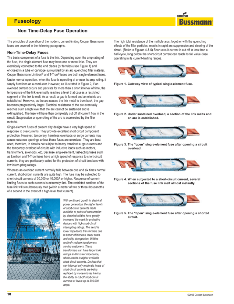
Fuseology Non Time-Delay Fuse Operation The principles of operation of the modern, current-limiting Cooper Bussmann fuses are covered in the following paragraphs. Non-Time-Delay Fuses The basic component of a fuse is the link. Depending upon the amp rating of the fuse, the single-element fuse may have one or more links. They are electrically connected to the end blades (or ferrules) (see Figure 1) and enclosed in a tube or cartridge surrounded by an arc quenching filler material. Cooper Bussmann Limitron® and T-Tron® fuses are both single-element fuses. Under normal operation, when the fuse is operating at or near its amp rating, it simply functions as a conductor. However, as illustrated in Figure 2, if an overload current occurs and persists for more than a short interval of time, the temperature of the link eventually reaches a level that causes a restricted segment of the link to melt. As a result, a gap is formed and an electric arc established. However, as the arc causes the link metal to burn back, the gap becomes progressively larger. Electrical resistance of the arc eventually reaches such a high level that the arc cannot be sustained and is extinguished. The fuse will have then completely cut off all current flow in the circuit. Suppression or quenching of the arc is accelerated by the filler material. Single-element fuses of present day design have a very high speed of response to overcurrents. They provide excellent short circuit component protection. However, temporary, harmless overloads or surge currents may cause nuisance openings unless these fuses are oversized. They are best used, therefore, in circuits not subject to heavy transient surge currents and the temporary overload of circuits with inductive loads such as motors, transformers, solenoids, etc. Because single-element, fast-acting fuses such as Limitron and T-Tron fuses have a high speed of response to short-circuit currents, they are particularly suited for the protection of circuit breakers with low interrupting ratings. Whereas an overload current normally falls between one and six times normal current, short-circuit currents are quite high. The fuse may be subjected to short-circuit currents of 30,000 or 40,000A or higher. Response of currentlimiting fuses to such currents is extremely fast. The restricted sections of the fuse link will simultaneously melt (within a matter of two or three-thousandths of a second in the event of a high-level fault current). With continued growth in electrical power generation, the higher levels of short-circuit currents made available at points of consumption by electrical utilities have greatly increased the need for protective devices with high short-circuit interrupting ratings. The trend is lower impedance transformers due to better efficiencies, lower costs, and utility deregulation. Utilities routinely replace transformers serving customers. These transformers can have larger kVA ratings and/or lower impedance, which results in higher available short-circuit currents. Devices that can interrupt only moderate levels of short-circuit currents are being replaced by modern fuses having the ability to cut-off short-circuit currents at levels up to 300,000 amps. 10 The high total resistance of the multiple arcs, together with the quenching effects of the filler particles, results in rapid arc suppression and clearing of the circuit. (Refer to Figures 4 & 5) Short-circuit current is cut off in less than a half-cycle, long before the short-circuit current can reach its full value (fuse operating in its current-limiting range). Figure 1. Cutaway view of typical single-element fuse. Figure 2. Under sustained overload, a section of the link melts and an arc is established. Figure 3. The “open” single-element fuse after opening a circuit overload. Figure 4. When subjected to a short-circuit current, several sections of the fuse link melt almost instantly. Figure 5. The “open” single-element fuse after opening a shorted circuit. ©2005 Cooper Bussmann
