From: AAAI-82 Proceedings. Copyright ©1982, AAAI (www.aaai.org). All rights reserved.
A MODEL BASED VISION SYSTEM
FOR RECOGNITION OF MACHINE PARTS
Katsushi Ikeuchi
Yoshiaki Shirai
Computer Vision Section
Electrotechnical Laboratory
Umezono-l-l-4, Sakura-mura
Niihari-gun, Ibaraki, 305
Japan
ABSTRACT
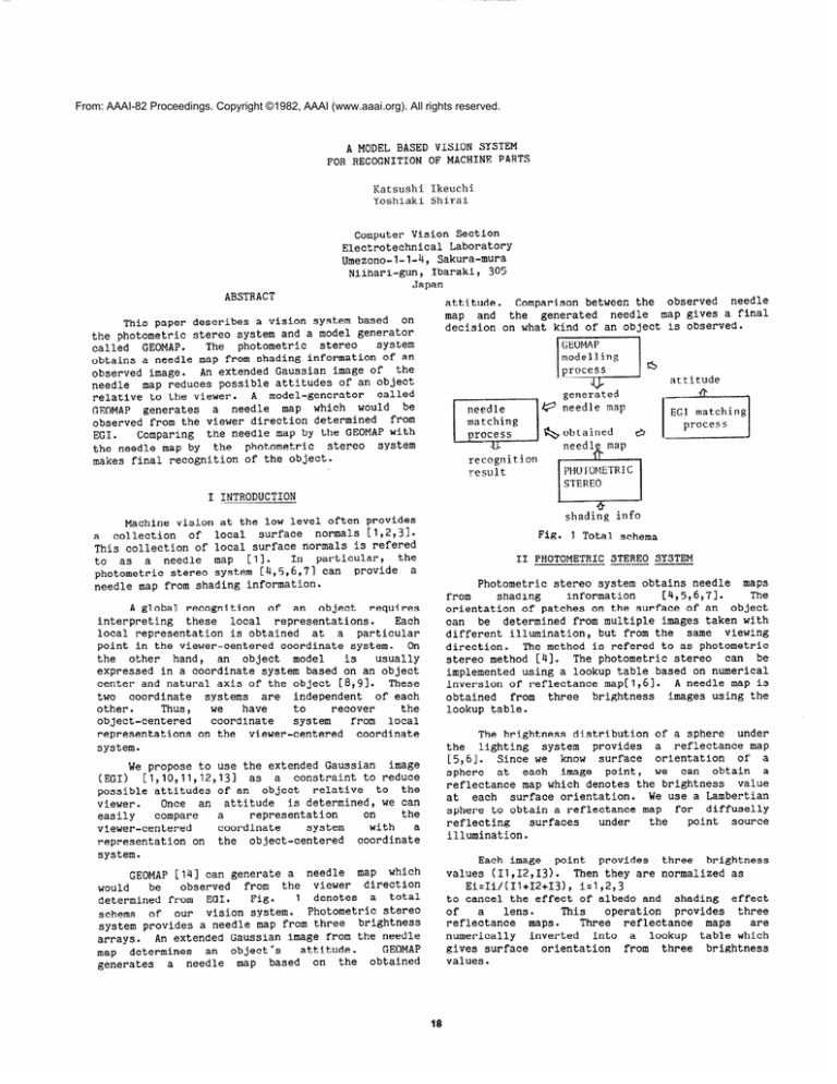
attitude. Comparison between the observed needle
map and the generated needle map gives a final
decision on what kind of an object is observed.
This paper describes a vision system based on
the photometric stereo system and a model generator
system
The photometric stereo
called GEOMAP.
obtains a needle map from shading information of an
observed image. An extended Gaussian image of the
needle map reduces possible attitudes of an object
relative to the viewer. A model-generator called
GEOMAP generates a needle map which would be
observed from the viewer direction determined from
Comparing the needle map by the GEOMAP with
EGI.
the needle map by the photometric stereo
System
makes final recognition of the object.
attitude
@
generated
needle map
&obtained
ti
recognition
result
I INTRODUCTION
shading info
Machine vision at the low level often provides
a collection of local surface normals [1,2,31.
This collection of local surface normals is refered
In particular, the
to as a needle map [Il.
photometric stereo system [4,5,6,71 can provide a
needle map from shading information.
Fig. 1 Total schema
II PHOTOMETRIC -STEREO SYSTEM
Photometric stereo system obtains needle maps
information
The
from
shading
[4,5,6,71.
orientation of patches on the surface of an object
can
determined from multiple images taken with
different illumination, but frbm the same viewing
direction. The method is refered to as photometric
stereo method [4]. The photometric stereo can be
implemented using a lookup table based on numerical
inversion of reflectance map[1,61. A needle map is
obtained from three brightness images using the
lookup table.
A global recognition of an object requires
interpreting these local representations.
Each
local representation is obtained at a particular
Point in the viewer-centered coordinate system. On
the other hand, an object model
is
usually
expressed in a coordinate system based on an object
Center and natural axis of the object [8,9]. These
two coordinate systems are independent of each
other.
Thus,
we
have
to
recover
the
object-centered coordinate
system
from local
representations on the viewer-centered coordinate
system.
The brightness distribution of a sphere under
lighting system provides a reflectance map
[5,61.
Since we know surface orientation of a
sphere at each image point, we can obtain a
refl.ectancemap which denotes the brightness value
at each surface orientation. We use a Lambertian
sphere to obtain a reflectance map for diffuselly
under
point source
surfaces
the
reflecting
illumination.
the
We propose to use the extended Gaussian image
(EGI) [1,10,11,12,131
as
a constraint to reduce
possible attitudes of an object relative to the
Once an attitude is determined, we can
viewer.
the
on
representation
easily
compare
a
coordinate
with
a
viewer-centered
system
representation on the object-centered coordinate
system.
Each image point provides three brightness
values (11,12,13).
Then they are normalized as
[l4] can generate a needle map which
observed from the viewer direction
would
be
1
denotes a total
Fig.
determined from EGI.
schema of our vision system. Photometric stereo
system provides a needle map from three brightness
arrays. An extended Gaussian image from the needle
GEOMAP
attitude.
map determines an object's
generates a needle map based on the obtained
GEOMAP
Ei=Ii/(I1+12+13),
i=1,2,3
to cancel the effect of albedo and shading effect
of
a
lens.
This
operation provides three
reflectance maps.
Three reflectance maps
are
numerically inverted into a lookup table which
gives surface orientation from thrke brightness
values.
18
1) Stable attitudes of models must be known.
If we have a solid model, we can determine the
position of gravity center. In particular,
GEOMAP has a solid model, and can determine
the position of gravity center. Then, we can
obtain stable attitudes of the model from the
We denote the
position of gravity center.
opposite direction to the gravity at the
stable attitude as t&e stability directnf
the mom.
2) The angle between the gravity direction and
the line of sight must be detected.
It is interesting that a human being also has
semicircular canals to detect the direction.
Fig 2 shows an example of needle maps obtained
from real objects (a cylinder, an octagonal prism,
and a square prism) using the system. A TV camera
looks down the objects from the ceiling. The
objects lie having their long axes along the x
coordinate
of
the
image
plane.
This
looking-down-tv method gives a good constraint on
the possible viewer directions as discussed in the
next section.
Since these three objects have
rectangular silhouette in this attitude, three
objects cannot be discriminated using the so-called
silhouette matching.
Let us assume that we can detect the angle
between the gravity direction and the line of sight
The gravity
from a level on a TV camera as rc? .
direction is parallel to the stability direction
from the definition. Also the line of sight has
always the same direction from the assumption of
orthographic projection. Thus the angle between
the stability direction and the line of sight has
the same angle 13 . In other words, the possible
line of sight direction locates on a circle on the
Gaussian sphere whose center corresponds to the
stability direction and whose radius corresponds to
the angle between the gravity direction and the
line of sight,Q . In particular, when TV camera
observes the object in the gravity direction as in
our case, the circle reduces to the center point.
For example, when a square prism is looked down
from the ceiling of the observer room, only six
the
points corresponding to prism's faces on
Gaussian sphere are necessary to be considered as
This
candidate directions of line of sight.
the
partial
under
works
also
constraint
observations.
The ratio of area projected onto the image
plane against the original surface area constrains
For
[ill.
possible line of sight direction
example, observing an ellipsoid from the long-axis
direction gives a smaller projected area than
looking at the same ellipsoid from the direction
perpendicular to the axis. Yet the surface area is
the same.
(a> Cylinder
(b) Octagonal prism
CC> Square prism
Fig. 2 Obtained needle maps from the
photometric stereo
We also must find the rotation of an object
around the line of sight. We use the principal EGI
inertia direction from the line of sight direction
We will use the 2-D axis for simplicity of
[ill.
calculation, where the calculations are also done
patch is visible from the
surface
only
if
direction.
above
can
be
The constraints mentioned
extended to treat partial observations. Partial
characteristics of
observation occurs due to
photometric stereo system. The photometric stereo
system can determine surface orientation at the
area where all three light sources project their
light directly. Our photometric stereo system can
determine surface orientation within the area where
the zenith angle of the surface normal is less than
60 degrees.
The ratio and the axis direction are
calculated at this area.
III ~DETERMINING ATTITUDE --OF AN OBJECT
There are three degrees of freedom in an
object's attitude relative to the viewer. Although
a brute force technique, such as search through the
space of possible attitudes, can be applicable to
matching of EGIs directly for determining attitude
of an object, we will reduce this search space
using constraints.
A.
Constraints on attitudes -of an object
---
We propose three kinds of constraints to
reduce possible attitudes of an object. (From now
on, we assume that image plane is perpendicular to
In other words, the image
the line of sight.
formation system is modelled using the orthographic
projection.)
B.
Knowing the gravity direction reduces possible
Two conditions must be satisfied to
attitudes.
apply this constraint to the observed data:
Determining attitude -using EGI
Comparing EGI from
19
observed data with EGI
cd1
from prototypes determines the attitude of an
object. An EGI of an object denotes surface-normal
distribution of the object [1,10,11,12,13].
We
implement EGI on the semi-regular geodesic dome
EGI at
from a two frequency dodecahedron [Ill.
EGI is
each attitude is calculated using GEOMAP.
stored as a two dimensional lookup table. Each
column corresponds to one attitude, while each raw
contains two kinds of information.
(1) projected area vs. surface area.
ratio
with
an
Comparing this registered
ratio determines whether the EGI
observed
distribution is necessary to be check at this
attitude or not.
(2) local EGI distribution
An EGI observed at this attitude is stored in
based
on
the
table
one-dimensional
an
geodesic-dome-tessellation. The EGI in the
table is aligned so that the least inertia axis
coincides with the x-coordinate on the image
plane.
Thus, the observed EGI should be
rotated to have the least inertia axis as the
direction before comparison.
Likelihood is calculated by determining whether
every observed EGI cell contains similar amount of
mass at the corresponding neighboring cells in the
The program determines the attitude
table [Ill.
obtaining the highest likelihood as the observed
attitude.
(b) Cylinder(45)
Octago.p.(45)
Square P.(45)
Square P.(138)
(a) Cylinder(l38)
----.
----_
t’
_l
i:-:-1
(c) Octagonal P. (138)
(d) Square P.(22)
Fig. 4 Prototypes and their EGIs
Table 1 shows a EGI comparison results.
A
needle map of a cylinder (Fig.2(a)) gives an EGI as
shown in Fig.3(a) and 0.8711 as the ratio. If the
needle map is assumed to come from a cylinder, the
ratio constraint reduces 240 possible attitudes
into 2 possible attitudes: direction 22 and 138.
See Fig. 4. At 22 direction, EGI comparison gives
0.3437
as likelihood value. If the same needle map
is assumed to come from a octagonal prisms, 22, 136
Under this
are possible attitudes.
and
138
highest
gives
the
assumption, direction 138
likelihood among the possible attitudes. At the
EGI comparison the observed EGI is too different to
be assumed as an EGI from the square prism.
Table
I
1
EGI comparison results
I CYLJNDER
CY LTNDER
22:
0.3305
I
OCTAGONAL
I’R IS?.!
22:
0.0
SQUARE
PRISM
22:
0.0
comes from the
The needle map in Fig. 3(c)
All objects have
planar surface of the prism.
planar surfaces. The direction 45 corresponds to
the direction observing the base of each prism.
See Fig. 4(b).
GEOMAP, developed by Kimura and Hosaka at ETL
is a program package to synthesize 3D object.
GEOMAP maintains 3D information of an object in the
program. GEOMAP has the following characteristics;
(0) GEOMAP has primitive objects.
(I) GEOMAP can move and rotate an object.
(2) GEOMAP can unify an object with another object
into a new object.
(3) GEOMAP can make constraint endowment.
(4) GEOMAP can make a 2D projection of an object
in any direction.
(5) GEOMAP can store/retrieve data of each object
to/from files.
(6) Maclisp at ETL can call GEOMAP directly with
commands to GEOMAP.
[141,
I’
\
‘,
\
(a) Cylinder (b) Octagonal prism (c) Square prism
Fig.3 Obtained EGIs from the needle maps
20
with
the generated
observed object.
treat
assumed
to
Our vision system is
We have precise information at
mechanical parts.
Thus, we can make 3D
each candidate object.
information of each candidate in GEOMAP using
and
operations,
movement operations, rotation
unification operations from primitive objects.
REFERENCES
Cl1
[21
II41
2
window-area
After calculating this E for all candidates, the
candidate obtaining the highest value will be
determined as the object observed at that time as
shown in Table 2.
Ii51
E63
Table 2 Needle-comparison results
-_
T----
--.--.~----y---_.
.- --7----
_
the
The authors would like to extend their sincere
appreciation to Prof. B.K.P. Horn of MIT for his
helpful discussions.
Thanks goes to Prof.
F.
Kimura of Univ.of Tokyo for permission of using
GEOMAP. GEOMAP is converted from VAX-FORTRAN to
TOPS20-FORTRAN.
The experimental part of this
paper was done using Mac-Lisp installed on Dee
2020-2060 at ETL.
[31
protovf;bserve12+(g;roto-gpbservej2
i (fi
- -. ^--~ _-_‘2
Fi
identifies
ACKNOWLEDGMENTS
GEOMAP generates a needle map so as to have
the same gravity position, to have the least
inertia direction as the x-coordinate axis, and to
have the same window size as the real image. Final
matching is made as
Ii{ 1 --'
map
The experiment shows that
extending
the
detectable area of a photometric stereo system not
only increases accuracy in final matching process
but
also
constrains
possible attitudes more
precisely.
Once the EGI system determines the attitude of
each candidate, GEOMAP can make a needle map of
each candidate in the direction.
Needle
map
comparison has two relative merits to a depth map,
which would be obtained by integrating the needle
map, comparison.
(1) The photometric stereo system does not assume
that an object surface is continuous. Thus,
we cannot integrate a needle map to obtain a
depth map. Even if we assume that an observed
surface is continuous, we cannot obtain a
depth map in case that needles are obtained at
multiple regions.
(2) Each needle may contain a measurement error.
Thus, errors accumulate during integration.
Reliability of a depth map degenerates towards
the end of integration.
E=
needle
, [71
81
91
101
111
Cl21
V CONCLUSION
Horn,
B.K.P.,
"SEQUINS
and
QUILLS
-Representation for Surface Topography." AI
Memo No. 536, AI Lab., MIT, 1979.
-Barrow, H.G. and Tenenbaum, J.M., l'Recovering
Intrinsic Scene Characteristics from Images."
Hanson, A.R. & Riseman, E.M., (Ed.) -----Computer
Vision Systems, Academic Press, New York,
1978.
Kender, J.R., "Shape from Texture," Ph.D.
Thesis, Computer Science Dept., CMU, 198Cr--~
-Woodham,
R.J.,
"Photometric
Stereo:
A
Reflectance
Map Technique for Determining
Surface Orientation from Image Intensity," in
Proc.
SPIE, Vol. 155, 1978.
~
-Ikeuchi, K., "Determining Surface Orientations
of Specular Surfaces by Using the Photometric
Stereo Method,"
IEEE
Trans.
PAMI,
Vol.PAMI-2, No.6, Nov. 1981, 661-66?
Silver,
W.M.,
"Determining
Shape
and
Reflectance Using Multiple Images," MS Thesis,
EECS, MIT, June 1980.
Coleman, E.N., and Jain,
R.,"Shape
form
Shading
for
Surfaces
with
Texture and
Specularity," in Proc.
IJCAI-81, Vancouver,
Aug. ,981, 652-657.
Binford, T.O.,"Visual Perception by Computer."
IEEE P
Conf.
on --Systems -~and Control, Miami,
Dee
1971.
Marr, D. and Nishihara, K.H., "Representation
and Recognition of the Spatial Organization of
Three-dimensional Shape." Proc.
R.
sot .
-Lond., B:200, (1978).
Smith, D.A.,"Using Enhanced Spherical Images
for Object Representation,' AI Memo
No. 530,
-AI Lab., MIT, 1979.
Ikeuchi,K.,"Recognition
of
Objects
Using
Extended Gaussian Image'" in Proc. IJCAI-81,
Vancouver, Aug. ,981, 595-600.
Ballard, D.H., and Sabbah, D.,"On Shape," in
Proc.
IJCAI-81,
Vancouver,
Aug.
1981,
607-612.
We propose a vision system based on the
photometric
and
GEOMAP.
stereo
system
The
photometric stereo system provides a needle map
from shading information. After constraints from
[I31
Bajcsy, R.,"Three-dimensional Scene Analysis,"
in Proc.
ICPR-80, Miani Beach, Dec. 1980,
[I41
Hosaka, M, Kimura, F. and Kakishita, N=, "A
Unified Method for Processing Polyhedra," in
Proc. IFIP, 1974, 768-772.
1064-1074.
EGI reduces possible attitudes of an object in
space, GEOMAP generates a needle map of an object
at the attitude. Comparing the observed needle map
21

