Burton™ subsea solutions
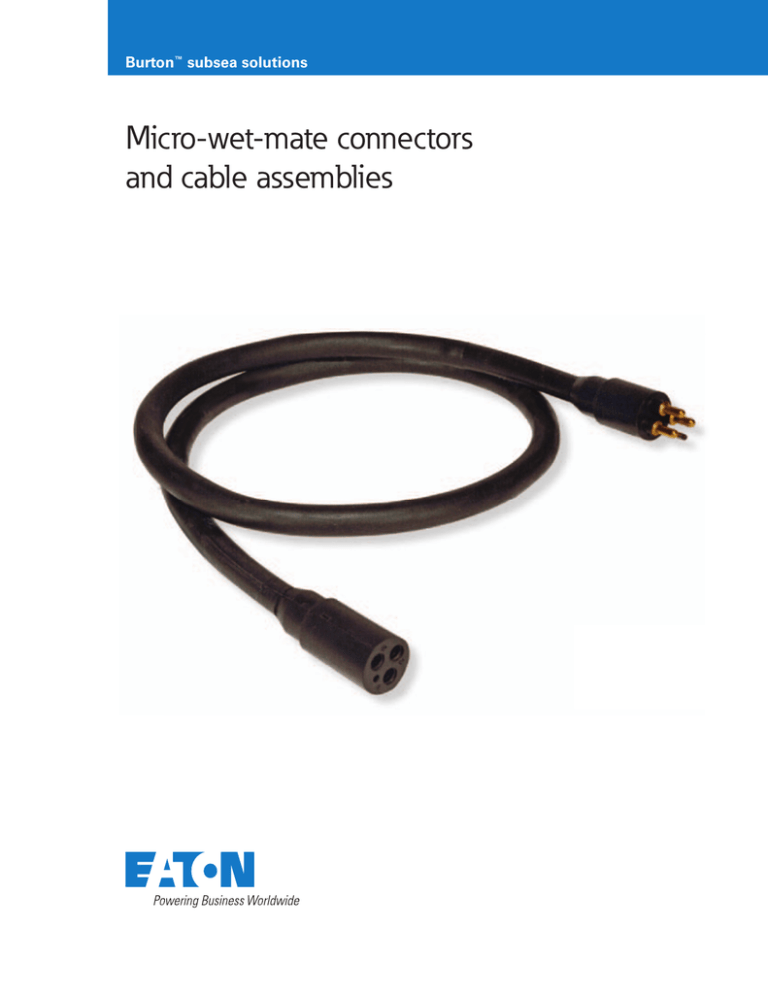
Micro-wet-mate connectors
and cable assemblies
Micro-wet-mate connectors and cable assemblies
Eaton’s micro-wet-mate solutions incorporate rugged designs
that provide 10,000 PSI pressure ratings and survive 1,000
mate and demate cycles.
These high-contact-density Burton™ connectors and cable
assemblies are available in bulkhead, inline overmolded, and
dummy-plug configurations:
• Up to 8 contacts in 0.61” (15.5mm) diameter shells
• Up to 16 contacts in 0.98” (25mm) diameter shells
Quick turn, application-specific-solution capabilities include:
• High voltages and currents
• High-speed-data including Ethernet
• Harsh environments including extreme pressures,
temperatures, mechanical stresses, and corrosive agents
Shell
Diameter
0.61”
(15.5mm)
0.98”
(25.4mm)
Number of
Contacts
Max.
Current
Max.
Voltage
Dielectric
Withstand
Inline
Wire Sizes
Bulkhead
Wire Sizes
3
7A
600V
<10uA @ 2000VDC
18AWG
20AWG
4
7A
600V
<10uA @ 2000VDC
18AWG
20AWG
5
3.5A
300V
<10uA @ 1500VDC
20AWG
22AWG
6
3.5A
300V
<10uA @ 1500VDC
20AWG
22AWG
8
3.5A
300V
<10uA @ 1500VDC
20AWG
22AWG
10
3A
300V
<10uA @ 1500VDC
20AWG
22AWG
16
2.5A
300V
<10uA @ 1500VDC
20AWG
22AWG
Miniaturized solutions available with seven
industry-standard contact arrangements
Gold plated, radiused pins resist corrosion
and reduce mating forces
Radiused pin shoulders protect insulators
from fraying
Integral threads facilitate rapid
locking-sleeve installation (shell size
M bulkhead connectors)
Reinforced neck resists damage during
aggressive demating
Color coded leads simplify
conductor tracing
Bulkhead connectors available in brass,
stainless steel, aluminum, titanium and
customer-defined materials
2
EATON Burton™ Subsea Connectors
Parameter
Ratings
Open Face Pressure
10,000 PSI
Mated Pressure
10,000 PSI
Operating Temperature
25°F to 140°F (-4°C to +60°C)
Mating Cycles
1000
Hi-Pot Voltage
Insulation Resistance
3 and 4 Contacts: 2000VDC
5 to 16 Contacts: 1500VDC
> 200 Megaohms @ 1000 VDC
Component
Materials and platings*
Bulkhead shell
Brass (UNS C36000), Stainless Steel (UNS 31600/UNS 31603), Titanium (6AL/4V, UNS R56400), or Aluminum (6061-T6/T651, UNS A96061)
Body
Proprietary Neoprene Blend
Contacts
Gold-Plated Beryllium Copper C173/C172 per ASTM B196
Orientation Pin
303/304 Stainless Steel
Cable Jacketing
Neoprene
Wire Insulation
Bulkhead Connectors: Extruded TFE, Inline Configurations: EPDM
Locking Sleeves
Delrin Bodies and 302 Stainless-Steel Snap Rings
Dummy Plugs
Proprietary Neoprene Blend
* Contact Eaton to discuss application-specific materials and platings
Burton™ subsea solutions are available in wet-mate shell
sizes up to 1.59” (41mm) diameter, dry-mate shell sizes 9 to
48, and overmolded and Pressure Balanced Oil Filled (PBOF)
configurations.
Please visit www.eaton.com/interconnect for more
information.
EATON Burton™ Subsea Connectors
3
Part number configuration
B-MC BH 8 M - S 001
Burton™ Micro-Wet-Mate Connector
Shell Type
(Table Below)
# of Contacts
(Drawings Below)
Contact Eaton
to discuss your
Ethernet requirements
Contact Type: M = Male Pin, F = Female Socket
Configuration
Bulkhead
Materials
Cable
Length
Dummy Plugs
Leave Blank
Leave blank
Bulkhead
Receptacles
Select from
Table Below
Standard: 001 (1 foot length)
Optional: enter any whole number up to 999
In-Line
Enter a Zero
Standard: 002 (2 feet length)
Optional: enter any whole number up to 999
Connectors do not include locking sleeves, please refer to the table below for locking-sleeve ordering information
Type
Shell Type
Type
Bulkhead Materials
Type
Bulkhead Materials
BH
Bulkhead Connector
B
Brass
A
Aluminum
DC
Dummy Connector
S
Stainless Steel
T
Titanium
IL
Inline Connector with Overmolded Cable
Shell size M insert arrangements 0.61” (15.5mm) diameter shells
Depicted with male-pin connectors
Three contacts
with alignment pin
Four contacts
with alignment pin
Five contacts
Six contacts
Eight contacts
Shell size A insert arrangements 0.98” (25mm) diameter shells
Depicted with male-pin connectors
Locking Sleeve Part Numbers
Ten contacts
4
Sixteen contacts
EATON Burton™ Subsea Connectors
Part Number
Application
B-MCDLSF
Female Connectors - 3 to 8 Sockets
B-MCDLSM
Male Connectors - 3 to 8 Pins
B-DLSAF
Female Connectors - 10 or 16 Sockets
B-DLSAM
Male Connectors - 10 or 16 Pins
Bulkhead and inline connectors mechanical drawings
Shell size M bulkhead connectors
0.750”
(19mm)
0.56”
(14.2mm)
1.097”
(27.8mm)
0.750”
(19mm)
0.750”
(19mm)
7/16-20UNF-2A
Locking-sleeve threads
0.317”
(8mm)
0.317”
(8mm)
7/16-20UNF-2A
Shell size A bulkhead connectors
0.750”
(19mm)
1.845”
(46.8mm)
1.65”
(41.9mm)
0.750”
(19mm)
0.99”
(25.4mm)
0.812”
(20.6mm)
1/2-20UNF-2A
1/2-20UNF-2A
Inline connectors
A
B
C
Male contacts
Female contacts
Shell Size M
Shell Size A
A
1.32” (33.4mm)
1.99” (50.5mm)
B
1.55” (39.4mm)
2.37” (60.2mm)
C
0.61” (15.5mm)
0.98” (25.4mm)
EATON Burton™ Subsea Connectors
5
Locking sleeve mechanical drawings
Shell size M (3 to 8 contacts) locking sleeves
1.625”
(41.28mm)
0.875”
(22.23mm)
0.864”
(21.95mm)
0.864”
(21.95mm)
B-MCDLSF
Used with female connectors
B-MCDLSM
Used with male connectors
Shell size A (10 and 16 contacts) locking sleeves
1.288”
(32.72mm)
1.450”
(36.83mm)
1.291”
(32.79 mm)
B-DLSAF
Used with female connectors
6
EATON Burton™ Subsea Connectors
1.325”
(33.66mm)
B-DLSAM
Used with male connectors
Installation instructions
Greasing and Mating
Above Water Mating
Submerged Mating in Depths Less Than Three Meters
Apply a silicone grease, such as Molykote 44 Medium, to approximately
10% of the depth of the female contact socket cavities.
Apply a silicone grease, such as Molykote 44 Medium, to approximately 30% of the
depth of the female contact socket cavities.
Confirm that the openings of all female sockets are sealed with grease and that a thin layer of grease covers the face of the female-contact connector.
Mate and demate the connector and inspect for grease on all male
contacts before final remating.
Fully mate the connector and remove excess grease.
Mate and demate by pushing straight in and pulling straight out and never at an angle. Always grasp the connector body and never try to demate by pulling on the cable.
Repeat these processes using new grease whenever male and female connectors are demated and remated.
Wiring Color Codes
Contact #
Wire Color
Contact #
Wire Color
Contact #
Wire Color
1
Black
7
White & Black
13
Red & White
2
White
8
Red & Black
14
Green & White
3*
Red
9
Green & Black
15
Blue & White
4
Green
10
Orange & Black
16
Black & Red
5
Orange
11
Blue & Black
6
Blue
12
Black & White
* Three-pin connectors utilize a green wire on pin #3.
Dummy plugs should be used on all unmated connectors to protect contacts
from corrosion and mechanical damage.
EATON Burton™ Subsea Connectors
7
For additional information
• Visit www.eaton.com/interconnect
• Call 805.484.0543
• Email cicustomer.service@eaton.com
Eaton
1000 Eaton Boulevard
Cleveland, OH 44122
United States
Eaton.com
Customer Service
750 West Ventura Blvd.
Camarillo, CA 93010
Phone: 805.484.0543 or
800.840.0502
www.eaton.com/interconnect
© 2014 Eaton
All Rights Reserved
Printed in USA
Publication No. BR800006EN
February 2016
Eaton is a registered trademark.
All other trademarks are property
of their respective owners.


