mounting accessories Notification
advertisement
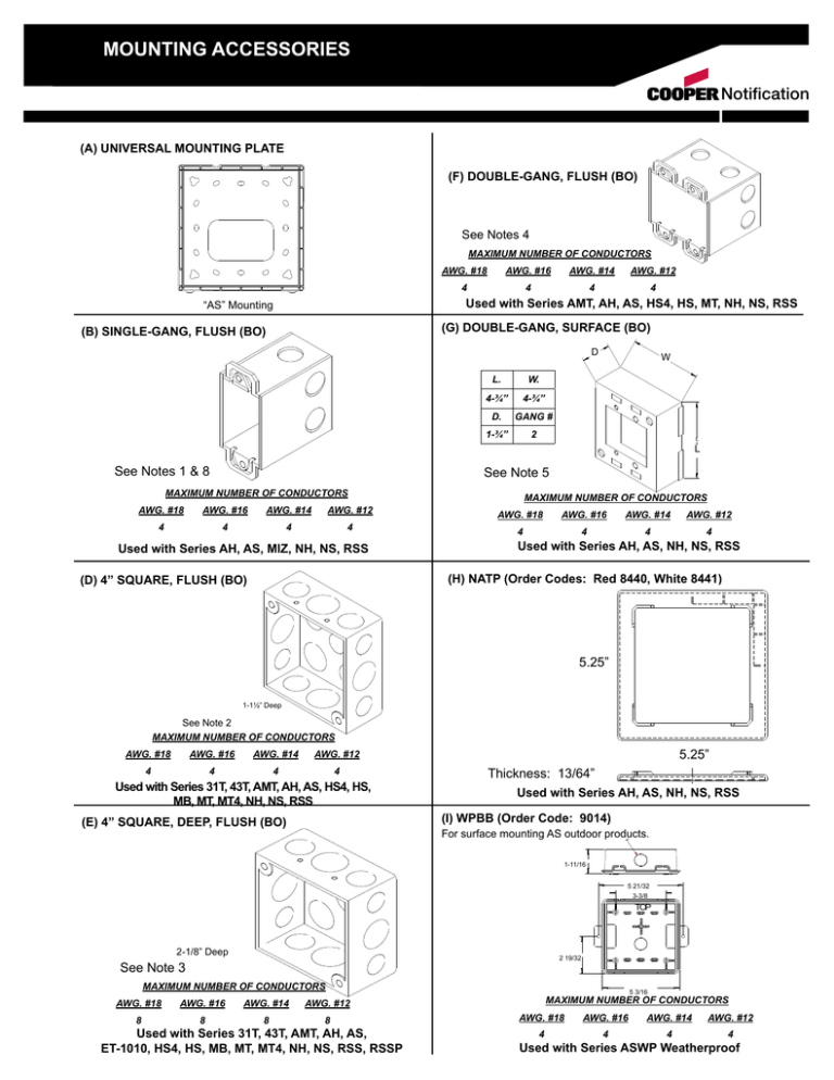
Mounting Accessories Notification (a) universal mounting plate (f) double-gang, flush (bo) See Notes 4 MAXIMUM NUMBER OF CONDUCTORS AWG. #18 AWG. #16 AWG. #14 AWG. #12 4 4 4 4 Used with Series AMT, AH, AS, HS4, HS, MT, NH, NS, RSS “AS” Mounting (g) Double-gang, surface (bo) (b) single-gang, flush (bo) DD L. W. 4-¾” 4-¾” D. GANG # 1-¾” 2 W W L L See Notes 1 & 8 See Note 5 MAXIMUM NUMBER OF CONDUCTORS AWG. #18 AWG. #16 AWG. #14 AWG. #12 4 4 4 4 Used with Series AH, AS, MIZ, NH, NS, RSS MAXIMUM NUMBER OF CONDUCTORS AWG. #18 AWG. #16 AWG. #14 AWG. #12 4 4 4 4 Used with Series AH, AS, NH, NS, RSS (h) natp (Order Codes: Red 8440, White 8441) (d) 4” square, flush (bo) 5.25” 1-1½” Deep See Note 2 MAXIMUM NUMBER OF CONDUCTORS AWG. #18 AWG. #16 AWG. #14 AWG. #12 4 4 4 4 Used with Series 31T, 43T, AMT, AH, AS, HS4, HS, MB, MT, MT4, NH, NS, RSS (e) 4” square, deep, flush (bo) 5.25” Thickness: 13/64” Used with Series AH, AS, NH, NS, RSS (i) wpbb (order code: 9014) For surface mounting AS outdoor products. 1-11/16 5 21/32 3-3/8 TOP 2-1/8” Deep 2 19/32 See Note 3 MAXIMUM NUMBER OF CONDUCTORS AWG. #18 AWG. #16 AWG. #14 AWG. #12 8 8 8 8 Used with Series 31T, 43T, AMT, AH, AS, ET-1010, HS4, HS, MB, MT, MT4, NH, NS, RSS, RSSP 5 3/16 MAXIMUM NUMBER OF CONDUCTORS AWG. #18 AWG. #16 AWG. #14 AWG. #12 4 4 4 4 Used with Series ASWP Weatherproof (j) bb backbox (order codes: Red 2830, Gray 2349) Standard steel backbox with knockouts for interior surface mounting, concealed conduit mounting or semi-flush applications. It is painted to match the signal. (n) dbb backbox (Order code: 2955) Standard steel backbox provided with knockouts for interior surface mounting, concealed conduit mounting or semi-flush applications. It is painted to match the signal. 4 3-3/8 5 3-3/8 #8-32 TAP (2) HOLES #8-32 TAP (2) HOLES 3-3/8 4 3-3/8 4 PROVIDED WITH KNOCKOUTS FOR ½” & ¾” CONDUIT See Note 9 PROVIDED WITH KNOCKOUTS FOR ½” & ¾” CONDUIT MAXIMUM NUMBER OF CONDUCTORS MAXIMUM NUMBER OF CONDUCTORS AWG. #18 AWG. #16 4 AWG. #14 4 2-3/16 AWG. #12 AWG. #18 AWG. #16 AWG. #14 AWG. #12 4 8 8 8 8 4 Used with Series 31T, 43T, AH, AS, MB, MT4, NH, NS, RSS (k) wbb weather resistant backbox (order codes: Red 2959, White 2960) Used with Series 31T, 43T, AMT, AH, AS, ET-1010, HS4, HS, MB, MT, MT4, NH, NS, RSS (o) rp-r retrofit plate (order code: 5042) 5-7/8 Sturdy die cast housing, threaded conduit hole and knockout for outdoor applications. It is painted to match the signal. 5” 4-1/8” 3-3/8” 3-3/8 13/32 2” TAPPED FOR ½” CONDUIT 0-1/4” ¼” DIA. (2) HOLES 3-3/8 3/8” 4-1/8” 3-13/16 8 2-1/16” ½” KNOCKOUT MAXIMUM NUMBER OF CONDUCTORS AWG. #18 AWG. #16 AWG. #14 AWG. #12 4 4 4 4 3-13/16 Used with Series 31T, 43T, AHWP, ET-1010, MB, MT4 (l) isp2 surface adapter (order code: Red 3194, White 3195) 5-1/4” SQ. Used with Series 31T, 43T, AMT, AH, AS, CH70, E70, ET70, ET1010, ET-1080, HS4, HS, MB, MT, MT4, NH, NS, RSS (p) sbb backbox (order codes: Red 3204, White 3193) For surface mounting speakers, chimes, andelectronic applications. 3-9/16 5-9/16 See Note 11 3-3/8 5-1/2 3 45/64 4 5/32 ¾” KNOCKOUTS (EACH SIDE) 3-3/8 ½” KNOCKOUTS (EACH SIDE) MAXIMUM NUMBER OF CONDUCTORS 29/32 4 5/32 1 3/16 Used with Series AMT, CH70, E70, ET70, HS4, HS, MT (m) iob backbox (Order Codes: Red 5046, White 5047) For surface mounting MT products. AWG. #18 AWG. #16 AWG. #14 AWG. #12 8 8 8 8 Used with Series 43T, AMT, CH70, E70, ET70, ET-1080, HS4, HS, MB, MT, NH, NS, RSS (Q) 4” square deep w/ extension ring, flush (bo) KNOCKOUTS FOR ½” CONDUIT (TOP, BOTTOM) 2-5/8 5-21/32 5-1/4 SQ. 3-3/8 SQ. TOP See Note 6 EXT. RING DEPTH AWG. #18 2-5/8 See Note 10 MAXIMUM NUMBER OF CONDUCTORS AWG. #18 AWG. #16 AWG. #14 AWG. #12 8 8 8 8 Used with Series AMT, ET70WP, HS4, HS, MT, MTWP AWG. #16 AWG. #14 AWG. #12 2-1/8” DEEP 1-1/2” 2-1/8” 8 8 8 8 4 8 8 8 1-1/2” DEEP Used with Series CH70, CH90, E70, ET70, E90, ET90, ET-1080 (R) sfp semi-flush plate (order codes: Red 2957, White 2958) Stamped aluminum surface wall plate which mounts behind the basic unit and serves to cover recessed backboxes in semi-flush mounting applications. It is painted to match the signal. (v) ssb-4 ceiling support bridge (order code: 3380) Provisions for (4) J-nuts #8-32 ib 3-3/8” square Material: Steel 5/16 6 3-3/8 6-1/2” #8-32 TAP (2) HOLES 3-3/8 6 23-3/4” Used with Series 31T, 43T, AMT, AH, AS, CH70, E70, ET70, ET-1010, ET-1080, HS4, HS, MB, MT, MT4, NH, NS, RSS Used with Series CH70, CH90, E70, ET70, E90, ET90, ET-1080 (s) ap adapter plate (order code: 2961) (w) 411/16” square, deep surface (b0) Stamped aluminum adapter plate designed for applications where semi-flush installations cannot be used. The plate can be mounted to standard octagon or round backboxes single or double gang boxes or plaster rings. The backbox and basic unit are then fastened to the plate. This type mounting is referred to as a concealed conduit installation. It is painted to match 5/16 the signal. 6 3-3/8 #8-32 TAP (4) HOLES See Note 7 6 3-3/8 MAXIMUM NUMBER OF CONDUCTORS Used with Series 43T, MB AWG. #18 AWG. #16 AWG. #14 AWG. #12 10 10 10 10 Used with Series SM, DSM (T) wPSBB-R (Order Codes: Red 9751, White 3033) 1-11/16 (x) shbb square, surface backbox (order codes: Red 7254, White 7255) 1-9/16 11/16 5 21/32 3-3/8 1/2 TOP Used with Series RSSWP Weatherproof 5 3-3/8 2 19/32 3-3/8 5 5 3/16 MAXIMUM NUMBER OF CONDUCTORS AWG. #18 AWG. #16 AWG. #14 AWG. #12 8 8 8 8 (U) 5” Square backbox w/ extension ring, flush (bo) Used with Series 43T, AH, AS, MB, NH, NS, RSS (y) ser-R SQUARE SEMI-FLUSH EXTENSION RING (Order Codes: Red 3045, White 3049) 5” 1-9/16" 5" 5” 5” 2 - 7/8” 3-3/8" 3-3/8" 5" 5” Used with Series CH70, CH90, E70, ET70, E90, ET90, ET-1080 Used with Series CH70 E70, ET70 (z) sbl-2 backbox (order codes: Red 6988, White 6989) 1- 11/16 11-16 6 7/64 3-3/8 (DD) CBb-8 8” ceiling Speaker Backbox (order code: 3314) 125/16 12-5/16 9-3/4 9-3/4 4-1/16 4-1/16 3-3/8 115/8 11-1/4 10 15/16 Used with Series RSSP See Note 12 (AA) E50SB-R (order codes: Red 0230, White 0231) Used with Series S 8” Ceiling Speakers (EE) E60 Extension Ring (Order Code: Red 3578, White 3757) Used with Series E50 (BB) E50SSB-R (order codes: Red 0232, White 0233) (FF) ZBB (Order Codes: Red 6036, White 6045) Used with Series E50 (CC) ssb-8 8” ceiling support bridge (order code: 3573) 23.750 TYP 10.000 7.956 1.000 TYP 10.000 7.956 8.500 14.463 8.500 Used with Series S 8” Ceiling Speakers UL ® S5391 S2652 THE CITY OF NEW YORK DEPARTMENT OF BUILDINGS 151-92-E (GG) WFP Plate (Order Codes: Red 4696, White 4697) 3 11/32 (JJ) ESBC backbox (Order Codes: Red 2751, White 2752) For indoor surface mounting of Exceder products. 6-7/8 2-0 3 1-11/16 6.816 (hh) WFPA Plate (Order Codes: Red 4696, White 4697) 57/8 5/ 8 MAXIMUM NUMBER OF CONDUCTORS AWG. #18 AWG. #16 AWG. #14 AWG. #12 4 4 4 4 Used with Exceder STC, HSC, HNC (KK) ESB-KIT (Order Codes: Red 0533, White 0534) Trim Plate Kit for Exceder LED 57/8 Backbox dimensions for mps 4-3/4” H x 3-1/4” W x 2-1/4” D Used with Exceder LST, LHS, LHN (II) ESB Backbox (Oder Codes: Red 2749, White 2750) 4-3/4 2-1/16 (LL) LSBB Backbox (Oder Codes: Red 2402, White 2403) 5-3/8 5-1/8 For indoor surface mounting of Exceder products. MAXIMUM NUMBER OF CONDUCTORS AWG. #18 AWG. #16 AWG. #14 AWG. #12 4 4 4 4 Used with Exceder ST, HS, HN For indoor surface mounting of Exceder LED products. MAXIMUM NUMBER OF CONDUCTORS AWG. #18 AWG. #16 AWG. #14 AWG. #12 4 4 4 4 Used with Exceder LST, LHS, LHN (MM) OSB (NN) LSPKBB Backbox (Oder Codes: Red 0756, White 0757) 4.69 2.08 6.23 Used with ET1080 General Notes 1. 2. 3. 4. 5. 6. 7. 8. 9. 10. 11. 12. For indoor surface mounting of Exceder LED Speaker products. MAXIMUM NUMBER OF CONDUCTORS AWG. #18 AWG. #16 AWG. #14 AWG. #12 4 4 4 4 Used with Exceder LSPK, LSPST FIGURE B IS TYPICAL OF A STEEL CITY LXM-WOW BOX OR EQUAL. FIGURE B SHOULD BE A 3.5” DEEP BACKBOX FOR CONDUIT INSTALLTIONS AND IS TYPICAL OF A STEEL CITY CY-½ BOX OR EQUAL. FIGURE D IS TYPICAL OF A STEEL CITY 52151 BOX OR EQUAL. FIGURE E IS TYPICAL OF A STEEL CITY 52171 BOX OR EQUAL. FIGURE F IS TYPICAL OF TWO STEEL CITY LXM-WOW BOXES OR EQUAL. FIGURE G IS TYPICAL OF A WIREMOLD 5748-2 BOX OR EQUAL. FIGURE Q IS TYPICAL OF A STEEL CITY 52171 BOX WITH A STEEL CITY 53151 EXTENSION RING OR EQUAL. FIGURE W IS TYPICAL OF A STEEL CITY 72171-1 BOX OR EQUAL. USE 3.5 DEEP BACKBOX ON ALL MIZ PRODUCTS WHEN EMT CONDUIT IS USED. WHEN USED WITH AC HORN (J), “BB” MUST BE USED FOR SURFACE MOUNT. HS4, HS, MT OR MTWP STROBE ARE FOR OUTDOOR MOUNTING. USE WITH SERIES RSSP. FIGURE U IS TYPICAL OF A RANDL INDUSTRIES BACKBOX. (“Total Number of conductors shall be in accordance with NEC table 314.16 (B)”). X X X X X X X X X X X X X X X X X X X X X X X X X X X X X X X X X X X X X X X X X X X X X X X X X X X X X X X X X X X X X X X X X X X X MOUNTING NOTES Series Exceder LED - LSPK, LSPST Series Exceder LED - LST, LHS, LHN Series Exceder - ST, HS, HN X X X X 2 3 4 X X X X 1 X X X X X X X X X X X X X X X X X X X X X X X X X X X X X X X X (JJ) ESBC Backbox (LL) LSBB Backbox (NN) LSPKBB Backbox X X Caution: The mounting options figures show the maximum number of field wires (conductors) that can enter the backbox used with each mounting option. If these limits are exceeded, there may be insufficient space in the backbox to accommodate the field wires and stresses from the wires could damage the product. Although the limits shown for each mounting option comply with the National Electrical code (NEC), Wheelock recommends use of the largest backbox option and the use of approved stranded field wires whenever possible, to provide additional wiring room for easy installation and minimum stress on the product from wiring. Caution: Check that the installed product will have sufficient clearance and wiring room prior to installing backboxes and conduit, especially if sheathed multiconductor cable or 3/4” conduit fittings are used. 1. Mounting hardware for each mounting option is supplied. 2. Conduit entrances to the backbox should be selected to provide sufficient wiring clearance for the installed product. When extension rings are required, conduit should enter through the backbox, not the extension ring. Use Steel City #53151 (1-1/2” deep) or #53171 (2-1/8” deep) extension rings (as noted in the mounting options) or equal with the same cut-out area. 3. When terminating field wires, do not use more lead length than required. Excess lead length could result in insufficient wiring space for the appliance. 4. Use care and proper techniques to position the field wires in the backbox so that they use minimum space and produce minimum stress on the product. This is especially important for stiff, heavy gauge wires and wires with thick insulation or sheathing. 5. Do not pass additional wires (used for other than the appliance) through the backbox “unless the backbox is of a sufficient size to permit additional wiring as described in NEC 314.16 (B)”. Such additional wires could result in insufficient wiring space for the appliance. NOTE: Due to continuous development of our products, specifications and offerings are subject to change without notice in accordance with Wheelock Inc. standard terms and conditions. Speaker Excede LED LED Z1000 S1100 S9004 S9006 S8100 S4000 S3000 S2400 S2000 S1700 S1500 S0310 S1610 S1611 S0800 S0800 S0710 S0600 S0510 S0500 S0410 X S0310 S1610 S0410 S9008 Data Sheet Number(s) Series Exceder - STC, HSC, HNC Series Z Series S8 Series RSSWP(1), ASWP(2), AHWP(3), MTWP(4), MT-12/24(4), ET70WP(4) Series AS/AH Series AMT Series SM/DSM Series HS4/HS Series MT X X X X Series MIZ/MIZ-TC Series E60 Series E70/ET70 X X X X Series MB Motor Bells Series ET1010 Series ET80 Sereis CH Series 43T Bells Series E50 Series 31T Series RSSP Series RSS/RSSR X X X X X X X X X X Exceder (X) SHBB (WSI) Shallow Surface (Y) SER Semi-Flush Extension Ring (Retrofit Appl.) (Z) SBL-2 Surface (WSI) Note 11 (AA) E50SB Backbox for E50 Speaker (BB) E50SSB Backbox for E50 Speaker Strobe (CC) SSB-8 8” Speaker Support Tile Bridge (DD) CBB-8 8” Ceiling Speaker Backbox (EE) E60 Extension Ring (FF) ZBB (II) ESB Backbox X X X Exceder (V) SSB-4 Ceiling (WSI) Support Bridge (W) 4.6875” x 4.6785” x 2.125” Deep Surface (BO) X X X X X X Exceder (A) Universal Mounting Plate (B) 1-GANG x 2” Deep - Flush (BO) Note 1 & 8 (D) 4” x 4” x 1.5” Deep - Flush (BO) Note 2 (E) 4” x 4” x 2.125 Deep - Flush (BO) Note 3 (F) 2-Gang x 3.5” Deep - Flush (BO) Note 4 & 8 (G) 2-Gang x 1.75” Deep - Surface (BO) Note 5 (H) NATP Trim Plate (I) WPBB-R Weatherproof Backbox for ASWP (J) BB Surface (WSI) Note 9 (K) WBB Weatherproof (WSI) (L) ISP Adapter (WSI) for Square Products (M) IOB Surface & Weatherproof (WSI) Note 10 (N) DBB Surface (WSI) (O) RP-R Retrofit Plate (P) SBB Surface (WSI) Note 11 (Q) 4” x 4” x 2.125” Box w/ 1.5” Extension RingFlush (BO) Note 6 (R) SPT Semi-Flush Plate (WSI) (S) AP Adapter Plate (WSI) (T) WPSBB-R Weatherproof Backbox for RSSWP (U) 5” Square Backbox w/ Extension Ring, Flush (BO) Series E90/ET90 MOUNTING MATRIX BACKBOX MOUNTING HEIGHTS for WHEELOCK WALL MOUNTED HORIZONTAL STROBE APPLIANCES NFPA-72 (2002) 7.5.4* Appliance Location. Wall-mounted appliances shall be mounted such that the entire lens is not less than 2.0 m (80 in.) and not greater than 2.4 m (96 in) above the finished floor. Backbox Mounting Options* Series RSSP Flush and Surface Retrofit Plate 80 IN 6 IN (B) 1-Gang x 2” Deep - Flush (BO) Series Exceder ST, HS, HN Series MT and Series RSS Strobe AMT Multitone Strobe 80 IN 6 IN 80 IN 6 IN 80 3/4 5 1/4 79 1/8 6 7/8 80 IN 6 IN Series Exceder LED - LST, LHS, LHN 80 IN 79 6 IN Series Exceder LED Speakers LSPK, LSPST 80 IN 6 IN 7 (D) 4” x 4” x 1.5” Deep Flush (BO) 83 15/16 80 1/4 5 3/4 78 5/8 7 3/8 77 7/8 8 1/8 80 1/4 5 3/4 (E) 4” x 4” x 2.125” Deep Flush (BO) 83 15/16 80 1/4 5 3/4 78 5/8 7 3/8 77 7/8 8 1/8 80 1/4 5 3/4 (F) 2-Gang x 3.5” Deep Flush (BO) 80 3/4 5 1/4 79 1/8 6 7/8 78 3/8 7 5/8 (G) 2-Gang x 1.75” Deep Surface (BO) 79 /8 6 /8 78 /4 7 /4 77 /2 8 /2 (M) IOB Surface & Weatherproof (WSI) 77 /4 8 /4 (P) SBB Surface (WSI) 77 1/8 8 7/8 78 1/2 7 1/2 7 1 1 3 1 1 (Q) 4” x 4” x 2.125” Box w/ 1.5” Extension Ring - Flush (BO) 83 15/16 (U) 5” Square Backbox w/ Extension Ring, Flush (BO) 83 7/16 80 1/4 5 3/4 (X) SHBB (WSI) Shallow Surface 1 79 7 79 7 3 78 5/8 7 3/8 77 7/8 8 1/8 78 1/8 7 7/8 77 3/8 8 5/8 78 1/8 7 7/8 78 1/2 7 1/2 78 3/4 7 1/4 (Y) 4” x 4” x 1.5” Box w/ 1.5” Extension Ring Plate (BO) (Z) SBL-2 Surface (WSI) 80 1/2 (II) ESB Backbox 5.375” x 4.75” x 2.0625” 79 9/16 6 7/16 (LL) LSBB Backbox 4.53” x 2.76” x 1.98” (NN) LSPKBB Backbox 6.23” x 4.69” x 2.08” Series CH70 Chime Strobe Series ET80 Speaker Strobe Series E70 Speaker Strobe Series ET70 Speaker Strobe Series SA-70S Self Amplified Speaker Strobe Backbox Mounting Options* 80 IN 6 IN 80 IN 6 IN 80 IN 6 IN 80 IN 6 IN 80 IN 6 IN (P) SBB Surface (WSI) 77 ¾ 8¼ 79 3/16 6 13/16 77 ¾ 8¼ 77 ¾ 8¼ 79 3/16 6 13/16 (Q) 4” x 4” x 2.125” Box w/ 1.5” Extension Ring - Flush (BO) 77 ½ 7½ 80 6 78 ½ 7½ 78 ½ 7½ 80 6 78 7 79 ½ 5½ 78 7 78 7 79 ½ 5½ 78 ½ 7½ 80 6 (U) 5” Square Backbox w/ Extension Ring Flush (BO) (X) SHBB (WSI) Shallow Surface (Y) 4” x 4” x 1.5” Box w/ 1.5” Extension Ring Plate - Flush (BO) * Measured from Bottom of Backbox (Inches) NOTES: (BO) = By Others; (WSI) = Wheelock Product WE ENCOURAGE AND SUPPORT NICET CERTIFICATION 3 YEAR WARRANTY S7000 Mounting 4/13 NJ Location 273 Branchport Ave. Long Branch, NJ 07740 P: 800-631-2148 F: 732-222-8707 www.coopernotification.com Cooper Notification is Notification
