Document 13664358
advertisement
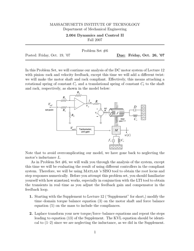
MASSACHUSETTS INSTITUTE OF TECHNOLOGY Department of Mechanical Engineering 2.004 Dynamics and Control II Fall 2007 Problem Set #6 Due: Friday, Oct. 26, ’07 Posted: Friday, Oct. 19, ’07 In this Problem Set, we will continue our analysis of the DC motor system of Lecture 12 with pinion–rack and velocity feedback, except this time we will add a different twist: we will make the motor shaft and rack compliant. Effectively, this means attaching a rotational spring of constant Cr and a translational spring of constant Ct to the shaft and rack, respectively, as shown in the model below: Note that to avoid overcomplicating our model, we have gone back to neglecting the motor’s inductance L. As in Problem Set #6, we will walk you through the analysis of the system, except this time we will be evaluating the result of using different controllers in the compliant system. Therefore, we will be using Matlab ’s SISO tool to obtain the root locus and step responses numerically. Before you attempt this problem set, you should familiarize yourself with how sisotool works, especially in conjunction with the LTI tool to obtain the transients in real–time as you adjust the feedback gain and compensator in the feedback loop. 1. Starting with the Supplement to Lecture 12 (“Supplement” for short,) modify the time–domain torque balance equation (3) on the motor shaft and force balance equation (5) on the mass to include the compliances. 2. Laplace transform your new torque/force–balance equations and repeat the steps leading to equation (13) of the Supplement. The KVL equation should be identi­ cal to (1–2) since we are neglecting the inductance, as we did in the Supplement. 1 Obtain the transfer function V (s)/Vs (s) of the compliant system without feed­ back. After substituting Cr = 2N · m/rad, Ct = 10N/m and the remaining numerical values from the Supplement, your transfer function should be 0.3162s . + 2s + 3 s2 You should use this transfer function in the rest of the problem set, even if you can’t get your algebra from question 1 to match it. 3. Now consider the complete feedback system, which includes the differential ampli­ fier with reference voltage input and velocity feedback. Write expressions for the open loop transfer function and the closed–loop transfer function of this system with the feedback gain K as a variable. 4. What is the order, type, and nature (i.e., overdamped, undamped, etc.) of this system? Back up your answer with a sketch of the open–loop zeros and poles. 5. What is the steady–state velocity of this system? What is the steady–state error? Provide an explanation based on the physics of the system. 6. Specify your system in the SISO tool and use the Analysis→Response to step command menu choice to plot the pole locations and step response for K = 1 and K = 10. Confirm that the step responses match qualitatively the pole locations and your steady–state prediction from question 5. 7. Explain the shape of the root locus that you see in the SISO tool panel based on the root locus sketching rules that we covered in class (but don’t attempt any quantitative verification of the root locus features.) 8. Now add an integrator to the forward path of the closed–loop system. Sketch the new block diagram and interpret the operation of the new system with the integrator. What would change in the physical implementation of the system? What is the meaning of the feedback signal and the reference voltage? 9. What is the steady–state output of the new system, as function of feedback gain K? Is the result consistent with the system type? Is the result consistent with your answers to questions 5 and 8? 10. Define the new system in the SISO tool (do not use the SISO tool’s option of adding an integrator to the compensator block; instead, define the open–loop transfer function anew, including the integrator, and import it as the plant.) Use the Analysis→Response to step command menu choice to plot the pole locations and step response for K = 85.4. Find the steady–state output from the numerical result and compare it with your analytical expression from question 9. Find also the percent overshoot. 11. Explain the shape of the new root locus from question 10 based on the root locus 2 sketching rules. 12. Use the expression you derived in question 9 to find the feedback gain K that would be required for the steady–state output to equal 0.99. Then modify the con­ troller gain in the SISO tool to equal the K value that you obtained and compute the step response. Verify that the steady–state output that Matlab produced matches the value of 0.99 and find the percent overshoot. 13. Define a new transfer function 85.4 × s + 0.1 s + 0.01 and import it as the Compensator C Block in the SISO tool. Obtain the new step response and compare it with the step responses from questions 10 and 12. What do you observe? (We will learn later in class that the new compensator represents a type of integral control called a lag compensator. The lag compensator would require replacement of the differential amplifier by a more complicated circuit.) 3
