Technical Data
Effective November 5, 2014
SP15 & SP20 – Heavy Duty
Switchpacks
Catalog#
Prepared by
Project
Date
Comments
Type
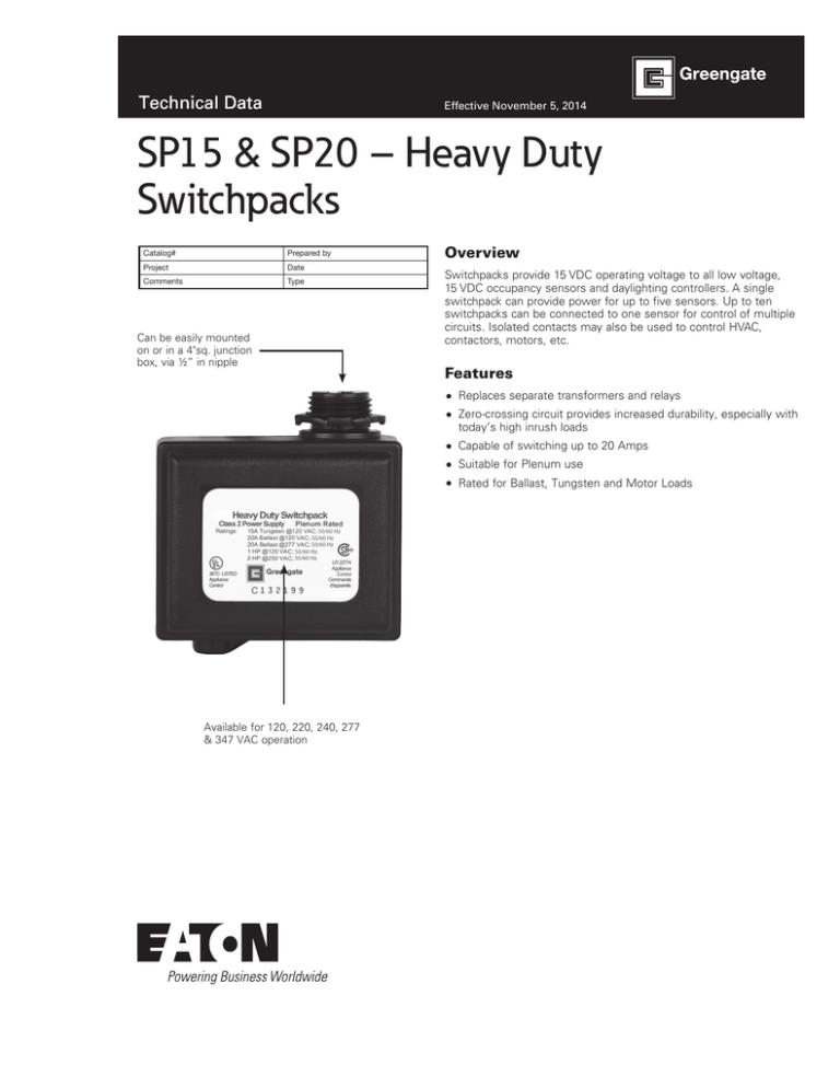
Can be easily mounted
on or in a 4"sq. junction
box, via ½” in nipple
Overview
Switchpacks provide 15 VDC operating voltage to all low voltage,
15 VDC occupancy sensors and daylighting controllers. A single
switchpack can provide power for up to five sensors. Up to ten
switchpacks can be connected to one sensor for control of multiple
circuits. Isolated contacts may also be used to control HVAC,
contactors, motors, etc.
Features
Replaces separate transformers and relays
Zero-crossing circuit provides increased durability, especially with
today’s high inrush loads
Capable of switching up to 20 Amps
Suitable for Plenum use
Rated for Ballast, Tungsten and Motor Loads
Available for 120, 220, 240, 277
& 347 VAC operation
Technical Data
November 2014
Specifications
Power
Requirements
Control
Ballast
Compatibility
NOTE
Operating
Environment
Housing
Motor Load
Size
Mounting
Standards
2
Input:
(120/277 VAC-SP20-MV), (347 VAC-SP15-347),
(220-240 VAC-SP20-240), 50/60 Hz operation.
Contacts are isolated and may be used to control
low voltage circuits
Output:
15 VDC 125mA to operate up to five Greengate
sensors
Connecting the 22 AWG red and blue control leads
to each other will close the relay contacts
Compatible with magnetic and electronic ballasts
The life of some compact fluorescent lamps (CFLs)
is shortened by frequent automatic or manual
switching. Check with the CFL and ballast manufacturer to determine effects of cycling
Temperature: 32°F - 104°F (0°C - 40°C)
Relative humidity: Less than 95%, non-condensing
For indoor use only
Medium impact injection molded housing. ABS
resin complies with UL 94V-0. Plenum rated for
external junction box mounting, with Teflon coated
leads
1 HP 120-240 VAC; 2 HP 250 VAC
2 15/16” x 2 7/16” x 1 11/16”
Mounts to the side of a 4" square box via 1/2"
knockout
UL, CSA Listed
www.coopercontrol.com
SP15 & SP20 – Heavy Duty Switchpacks
Description/Operation
The switchpack has two main components: a transformer and one
high current relay. The transformer has a primary line voltage input
and a secondary low voltage output. The low voltage output, 15
VDC, provides operating power to connected low voltage Greengate
occupancy sensors. When an occupancy sensor detects motion,
it electrically closes an internal circuit, pulling up the control signal
between the sensor and the switchpack. This signals the switchpack
to close its high current relay, turning the connected load on.
Applications
The switchpack is designed to work with low voltage sensors which
require switchpacks. It cannot be used with sensors designed for
use with any other low voltage relay systems. Consult sensor spec
sheets for other sensor relay combinations.
Technical Data
SP15 & SP20 – Heavy Duty Switchpacks
November 2014
Wiring Diagrams
A/B Switching
Three Way Switching
HOT
HOT
LINE
3. SWITCHES CAN BE USED TO TURN
LOADS ON OR OFF.
RECOMMENDED WIRE:
18-3 AWG STRANDED WIRE SHIELDED OR
NON/SHIELDED
RED (15 VDC)
SWITCHPACK
BLUE (CONTROL)
LOAD "B"
2. LOAD TURNS OFF, WHEN SENSOR
TIMES OUT.
**USE BLACK LEAD FOR 120 VAC.
USE ORANGE LEAD FOR 277 VAC.
CAP UNUSED LEAD.
3. SWITCHES CAN BE USED TO TURN
LOADS ON OR OFF.
BLUE
RECOMMENDED WIRE:
18-3 AWG STRANDED WIRE SHIELDED OR
NON/SHIELDED
BLACK (COMMON)
RED (15 VDC)
BLUE (CONTROL)
WHITE
1. WHEN SENSOR ACTIVATES, LOAD
TURNS ON.
LOAD "A"
BLUE
WHITE
**USE BLACK LEAD FOR 120 VAC.
USE ORANGE LEAD FOR 277 VAC.
CAP UNUSED LEAD.
**HOT
2. LOADS TURN OFF, WHEN SENSOR
TIMES OUT.
BLUE
AUTOMATIC MODE OPERATION:
1. WHEN SENSOR ACTIVATES, LOADS
TURN ON.
NEUTRAL
AUTOMATIC MODE OPERATION:
NEUTRAL
**HOT
LINE
SWITCHPACK
LOAD
WALL BOX 1
WALL BOX 2
BLUE
BLACK (COMMON)
THREE-WAY SWITCHES
RED (10-30 VDC)
RED (10-30 VDC)
TO ADDITIONAL SENSORS.
MAXIMUM 5 SENSORS PER SWITCHPACK.
BLUE (CONTROL)
BLACK (COMMON)
BLACK (COMMON)
Standard Configuration
2 Circuits, 1 Sensor
HOT
LINE
NEUTRAL
AUTOMATIC MODE OPERATION:
BLUE
1. WHEN SENSOR ACTIVATES, LOADS
TURN ON.
BLACK (COMMON)
2. LOADS TURN OFF, WHEN SENSOR
TIMES OUT.
BLUE (CONTROL)
TO ADDITIONAL SENSORS.
MAXIMUM 5 SENSORS PER SWITCHPACK.
WHITE
HOT
LINE
NEUTRAL
**USE BLACK LEAD FOR 120 VAC.
USE ORANGE LEAD FOR 277 VAC.
CAP UNUSED LEAD.
RED (15 VDC)
SWITCHPACK
BLUE (CONTROL)
TO ADDITIONAL SWITCHPACKS.
MAXIMUM 10 SWITCHPACKS PER SENSOR.
LOAD "B"
BLUE
BLACK (COMMON)
RECOMMENDED WIRE:
18-3 AWG STRANDED WIRE SHIELDED OR
NON/SHIELDED
BLACK (COMMON)
LOAD "A"
SWITCHPACK
3. SWITCHES CAN BE USED TO TURN
LOADS ON OR OFF.
RED (10-30 VDC)
BLUE (CONTROL)
RED (15 VDC )
**HOT
BLUE
LOAD
BLUE
BLUE (CONTROL)
SWITCHPACK
**USE BLACK LEAD FOR 120 VAC.
USE ORANGE LEAD FOR 277 VAC.
CAP UNUSED LEAD.
BLUE
RED (15 VDC)
NEUTRAL
WHITE
**USE BLACK LEAD FOR 120 VAC.
USE ORANGE LEAD FOR 277 VAC.
CAP UNUSED LEAD.
**HOT
2. LOAD TURNS OFF, WHEN SENSOR
TIMES OUT.
HOT
LINE
WHITE
1. WHEN SENSOR ACTIVATES, LOAD
TURNS ON.
**HOT
AUTOMATIC MODE OPERATION:
RECOMMENDED WIRE:
18-3 AWG STRANDED WIRE SHIELDED OR
NON/SHIELDED
TO ADDITIONAL SENSORS.
MAXIMUM 5 SENSORS PER SWITCHPACK.
BLUE (CONTROL)
BLACK (COMMON)
BLUE
RED (10-30VDC)
BLUE (CONTROL)
TO ADDITIONAL SENSORS.
MAXIMUM 5 SENSORS PER SWITCHPACK.
BLACK (COMMON)
Mounting
All connections are made via pigtails with twist-on
wire connectors.
NNote: Connect either the orange or black supply lead
to the power source, depending upon the power
requirements. Cap the unused lead.
www.coopercontrol.com
3
Technical Data
SP15 & SP20 – Heavy Duty Switchpacks
November 2014
Ordering
Catalog #
Ratings
Ballast
Tungsten
Motor (HP)
Output
SP20-MV
SP15-347
120/277 VAC, 50/60 Hz
347 VAC, 50/60 Hz
20A
15A
15A, 120V
NR
1HP-120V, 2HP-250V
NR
15 VDC, 125mA
15 VDC, 125mA
SP20-240
220-240 VAC, 50/60 Hz
20A
NR
NR
15 VDC, 125mA
Eaton
1000 Eaton Boulevard
Cleveland, OH 44122
United States
Eaton.com
Eaton’s Cooper Controls Business
203 Cooper Circle
Peachtree City, GA 30269
coopercontrol.com
© 2014 Eaton
All Rights Reserved
Printed in USA
Publication No. ACC141014
November 5, 2014
Eaton is a registered trademark.
All other trademarks are property
of their respective owners.


