HVAC/Refrigeration
HVACRS-13
HVAC/Refrigeration
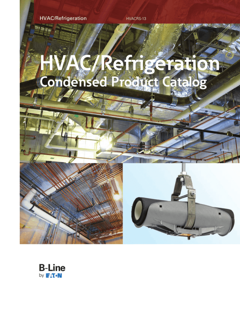
Condensed Product Catalog
Channel
Solid Back & Slotted (SH) Type Channel
• Versatile • Economical • Easy to Install •
Our complete selection of solid and slotted type channel (15/8” (41.3 mm) wide) is designed for ease of installation.
Pre-punched 9/16” (14.3 mm) x 7/8” (22.2 mm) slots 2” (50.8 mm) on center provide for full field flexibility without drilling.
Standard Finishes: DURA-GREEN™ (GRN) or Pre-Galvanized (GALV).
Standard Lengths: 10’ (3.05 mm) & 20’ (6.09 mm)
B22, B22SH, B24, B24SH Channels
B22SH
B24SH
Thickness
Part No.
in.
Height
in.
(mm)
Weight
Lbs./Ft. (kg/m)
12 Ga. (2.6)
15/8” (41.3)
1.90 (2.83)
12 Ga. (2.6)
15/8” (41.3)
1.82 (2.71)
B24
14 Ga. (1.9)
15/8” (41.3)
1.40 (2.08)
B24SH
14 Ga. (1.9)
15/8” (41.3)
1.34 (1.99)
B22
B22SH
B22
B24
(mm)
B22A, B22SHA Channels
B22SHA
Thickness
Part No.
in.
B22A
B22SHA
(mm)
Height
in.
(mm)
Weight
Lbs./Ft. (kg/m)
12 Ga. (2.6)
31/4” (82.5)
3.82 (5.69)
12 Ga. (2.6)
31/4” (82.5)
3.64 (5.42)
B22A
B26, B26SH Channels
B26SH
Thickness
Part No.
in.
(mm)
Height
in.
(mm)
Weight
Lbs./Ft. (kg/m)
B26
16 Ga. (2.6)
15/8” (41.3)
1.23 (1.84)
B26SH
16 Ga. (2.6)
15/8” (41.3)
1.07 (1.59)
B26
B54, B54SH Channels
Thickness
B54SH
Part No.
in.
(mm)
Height
in.
(mm)
Weight
Lbs./Ft. (kg/m)
B54
14 Ga. (1.9)
13/16” (20.6)
.97
(1.44)
B54SH
14 Ga. (1.9)
13/16” (20.6)
.91
(1.35)
B54
2
HVAC/Refrigeration
Channel Load Charts
Beam Span
In.
24
36
48
60
72
84
96
108
120
Channel Style
(mm)
Uniform Load and Deflection
Lbs.
(N)
Uniform Load @ Deflection =
1/240 Span
1/360 Span
In.
(mm)
Lbs.
(N)
Lbs.
(N)
(609)
B22
B22A
B24
B26
B54
1702
(7571)
2610* (11610)
1379
(6134)
1163
(5173)
465
(2068)
.056
.017
.057
.057
.108
(1.42)
(0.43)
(.1.45)
(.1.45)
(2.74)
1702
2610*
1379
1163
430
(7571)
(11610)
(6134)
(5173)
(1913)
1702
2610*
1379
1163
287
(7571)
(11610)
(6134)
(5173)
(1276)
(914)
B22
B22A
B24
B26
B54
1135
(5049)
2610* (11610)
919
(4088)
775
(3447)
310
(1379)
.126
.057
.128
.128
.243
(3.20)
(1.45)
(3.25)
(3.25)
(6.17)
1135
2610*
919
775
191
(5049)
(11610)
(4088)
(3447)
(849)
899
2610*
720
603
127
(3999)
(11610)
(3203)
(2682)
(565)
(1219)
B22
B22A
B24
B26
B54
851
2405
689
581
233
(3785)
(10698)
(3065)
(2584)
(1036)
.224
.125
.227
.228
.432
(5.69)
(3.17)
(5.76)
(5.79)
(10.97)
758
2405
607
509
108
(3372)
(10698)
(2700)
(2264)
(480)
505
2405
405
339
72
(2246)
(10698)
(1801)
(1508)
(320)
(1524)
B22
B22A
B24
B26
B54
681
1924
551
465
186
(3029)
(8558)
(2451)
(2068)
(827)
.351
.195
.355
.357
.676
(8.91)
(4.95)
(9.02)
(9.07)
(17.17)
485
1924
389
326
69
(2157)
(8558)
(1730)
(1450)
(307)
323
1640
259
217
46
(1437)
(7295)
(1152)
(965)
(204)
(1829)
B22
B22A
B24
B26
B54
567
1603
460
388
155
(2522)
(7130)
(2046)
(1726)
(689)
.505
.281
.511
.514
.973
(12.83)
(7.14)
(12.98)
(13.05)
(24.71)
337
1603
270
226
48
(1499)
(7130)
(1201)
(1005)
(213)
225
1139
180
151
32
(1001)
(5066)
(800)
(671)
(142)
(2133)
B22
B22A
B24
B26
B54
486
1374
394
332
133
(2162)
(6112)
(1752)
(1477)
(591)
.687
.383
.695
.699
1.324
(17.45)
(9.73)
(17.65)
(17.75)
(33.63)
248
1255
198
166
35
(1103)
(5582)
(881)
(738)
(155)
165
837
132
111
23
(734)
(3723)
(587)
(494)
(102)
(2438)
B22
B22A
B24
B26
B54
425
1202
345
291
116
(1890)
(5347)
(1534)
(1294)
(516)
.898
.500
.908
.913
1.730
(22.81)
(12.70)
(23.06)
(23.19)
(43.94)
190
961
152
127
27
(845)
(4275)
(676)
(565)
(120)
126
640
101
85
18
(560)
(2847)
(449)
(378)
(80)
(2743)
B22
B22A
B24
B26
B54
378
1069
306
258
103
(1681)
(4755)
(1361)
(1147)
(458)
1.136
.633
1.149
1.156
2.189
(28.85)
(16.08)
(29.18)
(29.36)
(55.60)
150
759
120
101
21
(667)
(3376)
(534)
(449)
(93)
100
506
80
67
14
(445)
(2251)
(356)
(298)
(62)
(3048)
B22
B22A
B24
B26
B54
340
962
276
233
93
(1512)
(4279)
(1228)
(1036)
(413)
1.403
.782
1.419
1.427
2.703
(35.63)
(19.86)
(36.04)
(36.24)
(68.65)
121
615
97
81
17
(538)
(2735)
(431)
(360)
(75)
81
410
65
54
11
(360)
(1824)
(289)
(240)
(49)
Based on simple beam condition using an allowable design stress of 25,000 psi (172 MPa) in accordance with MFMA, with adequate lateral bracing (see page
11 for further explanation). Actual yield point of cold rolled steel is 42,000 psi. To determine concentrated load capacity at mid span, multiply uniform load by
0.5 and corresponding deflection by 0.8. *Failure determined by weld shear.
Note: For SH channel loading, use 90% of the load values shown in this chart.
HVAC/Refrigeration
3
Channel Nuts
Twirl-Nut™
Part No.
Thread Size
Use With
Channels
3/8”-16
TN228
TN225
TN525
Nut Thickness
B22, B26, B54
B22, B26
B22, B26, B54
1/2”-13
1/2”-13
in.
(mm)
3/8”
(9.5)
1/2” (12.7)
3/8” (9.5)
Approx. Wt./100
Lbs.
(kg)
10.0 (4.53)
11.6 (5.26)
8.8 (3.99)
Standard Finish: Electro-Galvanized (ZN)
Spring Nut
Part No.
N228
N225
N528
N525
N2_ _ Series
N5_ _ Series
Thread Size
Use With
Channels
3/8”-16
Nut Thickness
B22, B26
B22, B26
B54
B54
1/2”-13
3/8”-16
1/2”-13
Approx. Wt./100
in.
(mm)
Lbs.
(kg)
3/8”
(9.5)
9.3
11.6
9.3
8.8
(4.22)
1/2” (12.7)
3/8”
(9.5)
3/8”
(9.5)
(5.26)
(4.22)
(3.99)
Standard Finish: Electro-Galvanized (ZN)
Nut Without Spring
Part No.
N228WO
N225WO
N525WO
Thread Size
Use With
Channels
3/8”-16
Nut Thickness
B22, B26. B54
B22, B26
B22, B26. B54
1/2”-13
1/2”-13
in.
(mm)
3/8”
(9.5)
1/2” (12.7)
3/8” (9.5)
Approx. Wt./100
Lbs.
(kg)
9.3 (4.22)
11.6 (5.26)
8.8 (3.99)
Standard Finish: Electro-Galvanized (ZN)
RESISTANCE TO SLIP
(With Safety Factor of 3)
Resistance to Slip
Thread
Size
3/8”-16
1/2”-13
Channel Nut Part
Numbers
12 ga. Channel
N228, N228WO, N528, TN228, NW528
N225, N225WO, TN225,
Pull-Out Strength
16 ga. Channel
(N)
Lbs.
(N)
800
(3560)
600
(2670)
600 (2670)
1000 (4450)
1000 (4450)
1500 (6670)
N525, N525WO, TN525, NW525
14 ga. Channel
Lbs.
Lbs.
(N)
(With Safety Factor of 3)
Pull-Out Strength
Thread
Size
Channel Nut Part
Numbers
12 ga. Channel
Lbs.
3/8”-16
1/2”-13
(N)
14 ga. Channel
Lbs.
(N)
16 ga. Channel
Lbs.
(N)
N228, N228WO, N528, TN228, NW528
1100
4890
1000
4450
1000
4450
N225, N225WO, TN225,
2000
8900
1400
6230
1000
4450
N525, N525WO, TN525, NW525
1500
6670
1400
6230
1000
4450
4
HVAC/Refrigeration
Hardware
BUZZNUT™ - Slip-On Lock Nut Washer
Part No.
Thread Size
SLWN-3/8
3/8”-16
SLWN-1/2
1/2”-13
Wt./100
Lbs.
(kg)
3.6
(1.63)
11.3 (5.12)
Standard Finish: Electro-Galvanized (ZN)
Combo Nut Washer
Part No.
(Fits all sizes of channel depths)
Thread
Size
Nut Thickness
NW525
1/2”-13
3/8” (9.5)
3.6 (1.63)
NW528
3/8”-16
3/8” (9.5)
11.3 (5.12)
in.
(mm)
Wt./100
Lbs.
(kg)
Standard Finish: Electro-Galvanized (ZN)
Hex Head Cap Screws
Part No.
& Size
Lbs.
(kg)
HHCS 3/8” x 3/4”
HHCS 3/8” x 1”
HHCS 3/8” x 11/4”
HHCS 3/8” x 11/2”
HHCS 3/8” x 13/4”
HHCS 3/8” x 2”
HHCS 3/8” x 21/4”
HHCS 3/8” x 21/2”
3.4
4.1
4.7
5.2
5.9
7.0
7.8
8.5
(1.54)
Part No.
& Size
Lbs.
(kg)
HHCS 1/2” x 7/8”
HHCS 1/2” x 1”
HHCS 1/2” x 11/4”
HHCS 1/2” x 11/2”
HHCS 1/2” x 13/4”
HHCS 1/2” x 2”
HHCS 1/2” x 21/2”
8.0
8.4
9.2
10.1
12.0
13.2
16.0
(3.63)
Wt./100
(1.86)
(2.13)
(2.36)
(2.67)
(3.17)
(3.54)
(3.85)
Wt./100
(3.81)
(4.17)
(4.58)
(5.44)
(5.99)
(7.26)
Standard Finish: Electro-Galvanized (ZN)
Square Washer
(15/8” (41.3mm) x 15/8” (41.3mm))
Standard Finishes:
Electro-Galvanized (ZN), DURA-GREEN™ (GRN)
B201/B202
Part No.
B201D/B202D
B201
B201D
B202
B202D
HVAC/Refrigeration
5
Hole
Size
Thickness
Wt./100
in.
(mm)
Lbs.
(kg)
7/16”
1/4”
(6.3)
1/4”
(6.3)
9/16”
1/4”
(6.3)
9/16”
1/4”
(6.3)
18
18
17
17
(8.1)
7/16”
(8.1)
(7.7)
(7.7)
Hardware & Brackets
Hex Nuts
Part No.
& Size
Wt./100
Lbs.
3/8
(kg)
1.5 (.68)
3.6 (1.63)
HN
HN 1/2
Standard Finish: Electro-Galvanized (ZN)
Lock Washers
Part No.
& Size
Lbs.
Wt./100
(kg)
LW 3/8
LW 1/2
0.6
1.3
(.27)
(.59)
Standard Finish: Electro-Galvanized (ZN)
Flat Washers
Part No.
& Size
Lbs.
Wt./100
FW 3/8
FW 1/2
1.7 (.77)
3.9 (1.77)
(kg)
Standard Finish: Electro-Galvanized (ZN)
Rod Couplings
Part No.
Size
Wt./100
Length
in.
(mm)
B655-3/8
3/8”-16
11/8” (28.6)
B655-1/2
1/2”-13
13/4” (44.4)
Lbs.
(kg)
3.6 (1.63)
11.3 (5.12)
Standard Finish: Electro-Galvanized (ZN)
All Threaded Rod
Part No.
& Size
Threads
Per Inch
ATR 3/8*
ATR
1/2
*Recommended Load
Wt./100 Ft. (3048.0 cm)
Lbs.
(kN)
Lbs.
(kg)
16
610
(2.17)
29 (13.15)
13
1130 (5.02)
53 (24.04)
*Specify Length: 72” (182.9 cm), 120” (304.8 cm), 144” (365.7 cm) lengths.
Standard Finish: Electro-Galvanized (ZN)
B409 - Single Channel Bracket
Length
in.
(mm)
Lbs.
(kN)
Lbs.
(kg)
B409-6
B409-9
B409-12
B409-14
B409-16
B409-18
B409-24
6”
9”
12”
14”
16”
18”
24”
(152.4)
1920
1280
960
800
730
640
480
(8.54)
152
195
232
274
314
347
450
(68.9)
(228.6)
(304.8)
(355.6)
(406.4)
(457.2)
(609.6)
Uniform Load
Wt./100
Part
No.
(5.69)
(4.27)
(3.56)
(3.25)
(2.84)
(2.13)
(88.4)
(105.2)
(124.3)
(142.4)
(157.4)
(204.1)
Standard Finish: Electro-Galvanized (ZN), DURA-GREEN™ (GRN)
6
HVAC/Refrigeration
Strut Fittings
Two-Hole Corner Angle
Wt./100 - 37 Lbs. (16.8 kg)
Two-Hole Splice Plate
Wt./100 - 37 Lbs. (16.8 kg)
B101
B129
B129PA
B101PA
Three-Hole Corner Angle
Wt./100 - 56 Lbs. (25.4 kg)
Three-Hole Splice Plate
Wt./100 - 55 Lbs. (24.9 kg)
B102
B141
B102PA
B141PA
Three-Hole Corner Plate
Wt./100 - 56 Lbs. (25.4 kg)
Three-Hole Corner Angle
Wt./100 - 56 Lbs. (25.4 kg)
B103
B140
B103PA
B140PA
Four-Hole Corner Plate
Wt./100 - 75 Lbs. (34.0 kg)
Four-Hole Corner Angle
Wt./100 78 Lbs. (35.4 kg)
B104
B143
B104PA
B143PA
Four-Hole Tee Plate
Wt./100 - 75 Lbs. (34.0 kg)
Two-Hole Corner Angle
Wt./100 - 37 Lbs. (16.8 kg)
B230
B133
B133PA
B230PA
Four-Hole Splice Plate
Wt./100 - 76 Lbs. (34.5 kg)
Two-Hole Corner Angle
Wt./100 - 37 Lbs. (16.8 kg)
B231
B341
B231PA
B341PA
Part numbers with PA are pre-assembled.
Standard Finish: Electro-Galvanized (ZN), DURA-GREEN™ (GRN)
HVAC/Refrigeration
7
Anchors
RAPID ROD™ Hangers - For Anchoring to Concrete
Catalog
Number
Shank Size
& Length
in.
1/4”
ARC-37-150
ARC-50-275
Drill/Hole
Diameter
(mm)
x 11/2” (6 x 38)
x 23/4” (9 x 70)
3/8”
Rod
Size
in.
(mm)
1/4”
(6)
3/8”-16
(9)
1/2”-13
3/8”
Allowable
Pull-Out Load
Lbs.
(kN)
500
500
(2.3)
(2.3)
1/4”
Concrete Socket
3/8” Concrete Socket
1/2” Concrete Socket
7195
7197
7198
For side mount concrete applications use the wood ARW-SW(s) with 1/4” drill bit.
RAPID ROD™ Hangers - For Anchoring to Wood
Catalog
Number
Shank Size
& Length
in.
Allowable Pull-Out
Load In Wood *
(mm)
1/4”
(6 x 25)
3/8”-16
1/4”
(6 x 51)
3/8”-16
(9 x 63)
3/8”-16
(9 x 63)
1/2”-13
(6 x 51)
3/8”-16
x 1”
x 2”
3/8” x 21/2”
3/8” x 21/2”
1/4” x 2”
ARW-37-100
ARW-37-200
ARW-37-250
ARW-50-250
ARW-37-200SW
Rod
Size
Lbs.
(kN)
375
375
375
775
375
(1.67)
(1.67)
(1.67)
(3.44)
(1.67)
Rapid Rod™ Universal Steel & Wood Socket
7187
* Loading for attaching to pine wood using a 1/8” (3.2mm) pilot hole.
SW - Side Mount
RAPID ROD™ Hangers - For Anchoring to Steel, Self-Drilling
Catalog
Number
Shank Size
& Length
in.
ARS
HN
ARS-37-200
ARS-37-100HN **
ARS-37-150
ARS-37-150HN **
ARS-37-100SW
ARS-25-150HD
ARS-37-150-HDHN **
ARS-50-150-HDHN **
7187
Rod
Size
(mm)
1/4”
3/8”-16
1/4”
3/8”-16
x 2” (6 x 51)
x 1” (6 x 25)
1/4” x 11/2” (6 x 38)
1/4” x 11/2” (6 x 38)
1/4” x 1” (6 x 25)
1/4” x 2” (6 x 51)
1/4” x 11/2” (6 x 38)
1/4” x 11/2” (6 x 38)
3/8”-16
3/8”-16
3/8”-16
3/8”-16
3/8”-16
3/8”-16
Allowable Pull-Out Load
12 Ga. Steel
14 Ga. Steel
Lbs.
(kN)
Lbs.
(kN)
390
365
390
365
390
200
200
200
(1.73)
290
365
290
365
290
400
400
400
(1.29)
(1.62)
(1.73)
(1.62)
(1.73)
(0.90)
(0.90)
(0.90)
(1.62)
(1.29)
(1.62)
(1.29)
(1.80)
(1.80)
(1.80)
Rapid Rod™ Universal Steel & Wood Socket
** For UL and FM LIstings,steel rapid rods should be installed with a retaining nut.
SW - Side Mount
Standard Finish: Electro-Galvanized (ZN)
8
HVAC/Refrigeration
Anchors
ADI Series - Drop-In Anchors
Catalog
Number
Thread
Size
Length
in.
ADI-37
3/8”-16
ADI-50
1/2”-13
Thread
Depth
(mm)
in.
19/16” (40)
2”
(51)
Drill/Hole
Diameter
(mm)
in.
(mm)
5/8” (16)
1/2” (13)
13/16” (21)
5/8” (16)
Setting tool included in each standard box.
AWA Series - Wedge Anchors
Catalog
Number
Thread
Size
Overall
Length
3/8"-16
21/4" (57)
11/4"
3/8"-16
23/4"
3"
31/2"
33/4"
5"
23/4"
33/4"
41/2"
51/2"
7"
15/8"
17/8"
23/8"
25/8"
37/8"
13/8"
1"
1
1 /2"
23/4"
41/4"
in.
AWA-37-225
AWA-37-275
AWA-37-300
AWA-37-350
AWA-37-375
AWA-37-500
AWA-50-275
AWA-50-375
AWA-50-450
AWA-50-550
AWA-50-700
3/8"-16
3/8"-16
3/8"-16
3/8"-16
1/2"-13
1/2"-13
1/2"-13
1/2"-13
1/2"-13
Thread
Length
(mm)
in.
(70)
(76)
(89)
(95)
(127)
(70)
(95)
(114)
(140)
(178)
Minimum
Embedment
Depth
(mm)
in.
Drill Hole
Diameter
(mm)
in.
(mm)
(32)
3/8”
(10)
(41)
3/8”
(10)
(47)
3/8”
(10)
3/8”
(10)
(66)
3/8”
(10)
(98)
3/8”
(10)
(35)
1/2”
(13)
(25)
1/2”
(13)
1/2”
(13)
(70)
1/2”
(13)
(108)
1/2”
(13)
15/8" (41)
(60)
21/4"
(38)
(57)
APC Series - Plastic Screw Anchors
• Kits contain 100 anchors, 100 screws, and 1 concrete drill bit
Catalog
Number
Screw
Size
Load Cap.
Tension
Lbs.
(kN)
APC-8K
#8 x 1”
110 (0.49)
70
(0.31)
APC-10K
#10 x 1”
140 (0.62)
90
(0.40)
APC-12K
#12 x 1”
140 (0.62)
90
(0.40)
Lbs.
Standard Finish: Electro-Galvanized (ZN)
HVAC/Refrigeration
9
(kN)
Load Cap.
Shear
Beam Clamps
65XT - Reversible Steel Beam Clamp
Wt./100 - 26 Lbs. (11.8kg)
Standard Finishes: Plain (PLN) or Electro-Galvanized (ZN)
Load Rating: 610 Lbs. (2.71kN)
B3031-3/8 - Light Duty Malleable C-Clamp
Wt./100 - 25 Lbs. (11.3 kg)
Standard Finishes: Plain (PLN) or Electro-Galvanized (ZN)
B3034 - Reversible Malleable C-Clamp
Standard Finishes: Plain (PLN) or Electro-Galvanized (ZN)
Part
No.
Rod
Size
B3034-3/8
B3034-1/2
Load Rating
Approx. Wt./100
Lbs.
(kN)
Lbs.
(kg)
3/8”-16
560
(2.49)
54
(24.5)
1/2”-13
810
(3.60)
51
(23.1)
B351 - Steel C-Clamp
Standard Finishes: Plain (PLN) or Electro-Galvanized (ZN)
Part
No.
Rod
Size
B351L-3/8
B351L-1/2
Load Rating
Approx. Wt./100
Lbs.
(kN)
Lbs.
(kg)
3/8”-16
230
(1.03)
41
(18.6)
1/2”-13
380
(1.71)
41
(18.6)
BH-2-4 - Parallel Strap Hanger
Wt./C 4.5 Lbs. (2.0 kg)
Standard Finishes: Black Zinc Phosphate Hanger - Electro-Galvanized Strap
Part
Number
Flange
Thickness
in.
BH-2-4
1/8”
(mm)
to 1/4” (3 to 6)
Max. Strap
Width
Static Load
Rating
in.
(mm)
Lbs.
11/2”
(38.1)
(kN)
200 (0.89)
BH-2-4-R - Right Angle Strap Hanger
Wt./C 12.4 Lbs. (5.6 kg)
Standard Finishes: Black Zinc Phosphate Hanger - Electro-Galvanized Strap
Part
Number
Flange
Thickness
in.
BH-2-4-R
1/8”
to
10
(mm)
1/4” (3 to 6)
Max. Strap
Width
Static Load
Rating
in.
(mm)
Lbs.
11/2”
(38.1)
(kN)
200 (0.89)
HVAC/Refrigeration
VIBRA-CLAMPS™
HVAC/Refrigeration
Catalog Number
Copper and Steel
Tubing O.D. size
Nominal Copper
Size
Nominal Pipe
Size
BVT025
1/4
--
--
BVT037
3/8
1/4
--
BVT050
1/2
3/8
--
BVP025
--
--
1/4
BVT062
5/8
1/2
--
BVT075
3/4
5/8
--
BVP037
--
--
3/8
BVP050
--
--
1/2
BVT087
7/8
3/4
--
BVP075
--
--
3/4
BVT100
1
--
--
BVT112
11/8
1
--
BVP100
--
--
1
BVT125
11/4
--
--
BVT137
13/8
11/4
--
BVT150
11/2
--
--
BVT162
15/8
11/2
--
BVP125
--
--
11/4
BVT175
13/4
--
--
BVT187
17/8
--
--
BVP150
--
--
11/2
BVT200
2
--
--
BVT212
21/8
2
--
BVT225
21/4
--
--
BVP200
23/8
--
2
BVT250
21/2
--
--
BVT262
25/8
21/2
--
BVP250
27/8
--
21/2
BVT300
3
--
--
BVT312
31/8
3
--
BVP300
31/2
--
3
BVT362
35/8
31/2
--
BVP350
4
--
31/2
BVT412
41/8
4
--
BVP400
41/2
--
4
BVP500
--
--
5
BVT612
61/8
6
--
BVP600
65/8
--
6
11
Pipe & Tubing Clamps
Rigid Conduit or Pipe Clamps
Conduit or
Pipe Size
Material
Thickness
in.
(mm)
in.
1/2”
(15)
3/4”
(20)
1”
11/4”
11/2”
2”
21/2”
3”
31/2”
4”
(25)
Part No.
B2008
B2009
B2010
B2011
B2012
B2013
B2014
B2015
B2016
B2017
16
14
14
14
12
12
12
12
11
11
(32)
(40)
(50)
(65)
(80)
(90)
(100)
Ga.
Ga.
Ga.
Ga.
Ga.
Ga.
Ga.
Ga.
Ga.
Ga.
Approx.
Design Load
Wt./100
(mm)
Lbs.
(kN)
Lbs.
(kg)
(1.5)
400
600
600
600
800
800
800
800
1000
1000
(1.78)
11
15
16
20
30
34
38
44
61
66
(5.0)
(1.9)
(1.9)
(1.9)
(2.6)
(2.6)
(2.6)
(2.6)
(3.0)
(3.0)
(2.67)
(2.67)
(2.67)
(3.56)
(3.56)
(3.56)
(3.56)
(4.45)
(4.45)
(6.8)
(7.2)
(9.1)
(13.6)
(15.4)
(17.2)
(19.9)
(27.6)
(29.9)
Standard Finish: Electro-Galvanized (ZN) - Additional sizes available.
O.D. Tubing Clamps
O.D.
Size
Part No.
B2024
B2025
B2026
B2027
B2008
B2030
B2032
B2011
B2038
B2042
in.
(mm)
3/8”
(9.5)
Material
Thickness
in.
16 Ga. (1.5)
16 Ga. (1.5)
16 Ga. (1.5)
1/2” (12.7)
5/8” (15.9)
3/4” (19.0)
7/8” (22.2)
11/8”
13/8”
15/8”
21/8”
25/8”
(mm)
(28.6)
(34.9)
(41.3)
(54.0)
(66.7)
Approx.
Design Load
Lbs.
(kN)
400 (1.78)
400 (1.78)
400 (1.78)
Wt./100
Lbs.
(kg)
8 (3.6)
9 (4.1)
10 (4.5)
16 Ga. (1.5)
400 (1.78)
10 (4.5)
16
14
14
14
12
12
400
600
600
600
800
800
11
15
17
20
32
35
Ga.
Ga.
Ga.
Ga.
Ga.
Ga.
(1.5)
(1.9)
(1.9)
(1.9)
(2.6)
(2.6)
(1.78)
(2.67)
(2.67)
(2.67)
(3.56)
(3.56)
(5.0)
(6.8)
(7.7)
(9.1)
(14.5)
(15.9)
Standard Finish: Electro-Galvanized (ZN) - Additional sizes available.
Copper Tubing Clamps
Part No.
B2024
B2025
B2026
B2028
B2030
B2032
B2034
B2038
B2042
B2046
B2050
B2054
Tubing
Size
in.
(mm)
1/4”
(6.3)
3/8”
(9.5)
Material
Thickness
in.
1/2” (12.7)
3/4” (19.0)
1” (25.4)
11/4” (31.7)
11/2” (38.1)
2” (50.8)
21/2” (63.5)
3” (76.2)
31/2” (88.9)
4” (101.6)
16
16
16
16
14
14
14
12
12
12
12
12
Ga.
Ga.
Ga.
Ga.
Ga.
Ga.
Ga.
Ga.
Ga.
Ga.
Ga.
Ga.
Design Load
Approx.
Wt./100
(mm)
Lbs.
(kN)
Lbs.
(kg)
(1.5)
400
400
400
400
600
600
600
800
800
800
800
800
(1.78)
8
9
10
11
15
17
19
32
35
39
54
61
(3.6)
(1.5)
(1.5)
(1.5)
(1.9)
(1.9)
(1.9)
(2.6)
(2.6)
(2.6)
(2.6)
(2.6)
(1.78)
(1.78)
(1.78)
(2.67)
(2.67)
(2.67)
(3.56)
(3.56)
(3.56)
(3.56)
(3.56)
(4.1)
(4.5)
(5.0)
(6.8)
(7.7)
(8.6)
(14.5)
(15.9)
(17.7)
(24.5)
(27.6)
Standard Finish: DURA-COPPER™ (DCU) - Additional sizes available.
12
HVAC/Refrigeration
ARMAFLEX® Clamps & Accessories
IPH Series
Inserts With Clamps & Inserts Only
• Engineered load-bearing inserts prevents insulation compression
• Innovative insulated pipe support
• Desirable “Foam-to-Foam” Bond
• Slip Data: 45 lbs. (0.20 kN) max
• Recommended Clamp Torque: 12-15 in-lbs. (1.3-1.7 Nm)
• Service Temperature Range
-58°F (-50°C) to +220°F (+105°C)
Insert Only
1/2”
Assembly
Insert & Clamp
Wall Insulation Thickness
Assembly
Part No.
IPH03812
IPH01212
IPH05812
IPH03412
IPH07812
IPH11812
IPH13812
IPH15812
IPH11012
IPH21812
IPH25812
IPH31812
IPH35812
IPH41812
IPH40012
IPH50012
IPH60012
Insert Only
Part No.
Pipe/Copper/OD
Size
3/8” O.D.
IPH03812WO
1/2” O.D.
IPH01212WO
5/8” O.D.
IPH05812WO
3/4” O.D.
IPH03412WO
7/8” O.D.
IPH07812WO
IPH11812WO 3/4” IPS & 11/8” O.D.
IPH13812WO
13/8” O.D.
IPH15812WO
15/8” O.D.
IPH11012WO 11/2” IPS & 17/8” O.D.
IPH21812WO
21/8” O.D.
IPH25812WO
25/8” O.D.
IPH31812WO
31/8” O.D.
IPH35812WO
35/8” O.D.
IPH41812WO
41/8” O.D.
IPH40012WO
4” IPS
IPH50012WO
5” IPS
IPH60012WO
6” IPS
Hanger
Size*
11/4”
11/4”
11/2”
11/2”
2”
2”
21/2”
21/2”
3”
3”
31/2”
4”
5”
6”
6”
8”
8”
3/4”
Wall Insulation Thickness
Assembly
Part No.
IPH03834
IPH01234
IPH05834
IPH03434
IPH07834
IPH11834
IPH13834
IPH15834
IPH11034
IPH21834
IPH25834
IPH31834
IPH35834
IPH41834
IPH40034
IPH50034
IPH60034
IPH80034
Insert Only
Part No.
Pipe/Copper/OD
Size
3/8” O.D.
IPH03834WO
1/2” O.D.
IPH01234WO
5/8” O.D.
IPH05834WO
3/4” O.D.
IPH03434WO
7/8” O.D.
IPH07834WO
IPH11834WO 3/4” IPS & 11/8” O.D.
IPH13834WO
13/8” O.D.
IPH15834WO
15/8” O.D.
IPH11034WO 11/2” IPS & 17/8” O.D.
IPH21834WO
21/8” O.D.
IPH25834WO
25/8” O.D.
IPH31834WO
31/8” O.D.
IPH35834WO
35/8” O.D.
IPH41834WO
41/8” O.D.
IPH40034WO
4” IPS
IPH50034WO
5” IPS
IPH60034WO
6” IPS
IPH80034WO
8” IPS
Hanger
Size*
2”
2”
2”
2”
21/2”
21/2”
3”
31/2”
31/2”
4”
5”
5”
6”
6”
6”
8”
10”
12”
* Recommended pipe hanger size for insulation thickness shown.
(Order hanger separately)
1” Wall Insulation Thickness
Assembly
Part No.
IPH05810
IPH03410
IPH07810
IPH11810
IPH13810
IPH15810
IPH11010
IPH21810
IPH25810
IPH31810
IPH35810
IPH41810
IPH40010
IPH50010
IPH60010
IPH80010
* Recommended pipe hanger size for insulation thickness shown.
(Order hanger separately)
IPH18230
ARMAFLEX® Insulation Tape
• 30 ft. (9.14 M) roll
Insert Only
Part No.
Pipe/Copper/OD
Size
5/8” O.D.
IPH05810WO
3/4” O.D.
IPH03410WO
7/8” O.D.
IPH07810WO
IPH11810WO 3/4” IPS & 11/8” O.D.
IPH13810WO
13/8” O.D.
IPH15810WO
15/8” O.D.
IPH11010WO 11/2” IPS & 17/8” O.D.
IPH21810WO
21/8” O.D.
IPH25810WO
25/8” O.D.
IPH31810WO
31/8” O.D.
IPH35810WO
35/8” O.D.
IPH41810WO
41/8” O.D.
IPH40010WO
4” IPS
IPH50010WO
5” IPS
IPH60010WO
6” IPS
IPH80010WO
8” IPS
Hanger
Size*
21/2”
21/2”
3”
3”
31/2”
31/2”
4”
4”
5”
5”
6”
6”
8”
8”
10”
12”
* Recommended pipe hanger size for insulation thickness shown.
(Order hanger separately)
Armaflex® is a registered trademark of Armacell.
HVAC/Refrigeration
13
VIBRA-CUSHION™ & Vibration Pads
B1999 - VIBRA-CUSHION
Wt./Carton 3.8 Lbs. (1.7 kg)
Packaged 20 Ft. (7.6 m) per carton.
VIBRA-CUSHION is designed for use with refrigeration lines, HVAC,
copper tubing, glass pipe and hydraulic lines. It
provides an energy-absorption barrier between the lines and the
mounting material and remains flexible thru its entire
service range of -75°F (-60°C) to +375°F (+199°C).
For Copper Tubing Type L & K
Nominal
Size
W
Length of
Vibra-Cushion
in.
(mm)
in.
(mm)
113/16”
213/16”
27/8”
35/8”
43/8”
57/16”
67/8”
(46.0)
3/8”
(10)
1/2”
(15)
3/4”
(20)
1”
11/4”
11/2”
2”
(25)
(32)
(40)
(50)
Use
Clamp No.
B2027
B2002
B2003
B2032
B2036
B2012
B2013
(58.7)
(73.0)
(92.1)
(120.6)
(138.1)
(174.6)
VRP Type - Rubber Cube Pad 3/4"
3/4"
(19 mm)
(19 mm)
L
Part
No.
Rated
Load
(Lbs.)
VRP-4
180
Dimensions
L
W
in.
2"
Approx. Wt.
Each
(mm)
in.
(mm)
(51)
2"
(51)
0.10 (.04)
Lbs.
(kg)
VRP-16
720
4" (101)
4" (101)
0.41 (.18)
VRP-324
14580
18" (457)
18" (457)
8.15 (3.69)
Standard Package: VRP-4 and VRP-16 (bulk)
VRP-324 (3 pcs.)
BVS Type - VIBRA-STRIP™ for 15/8" (41 mm) wide B-Line channel
14
Part
No.
Max. Load
Lbs. per
Lineal In.
BVS-12
40
Length
Std.
in.
Pkg.
(mm)
12" (305)
25
Approx. Wt.
Each
Lbs.
(kg)
0.46 (.21)
HVAC/Refrigeration
Vibration Pads
NNP Type - Ribbed Neoprene Pad 3/8" (9 mm) Thick
W
3/8"
(19 mm)
L
Rated
Load
Dimensions
Std.
Approx. Wt.
Each
(mm)
Pkg.
Lbs.
(kg)
(51)
48
.04
(.02)
3"
(76)
36
.10
(.04)
4"
(101)
24
.17
(.08)
6" (152)
6"
(152)
24
.39
(.17)
9" (228)
9"
(228)
Bulk
.87
(.39)
18" (457)
18" (457)
Part
No.
L
W
Lbs.
(kg)
in.
(mm)
in.
NNP-4
200
(8.89)
2"
(51)
2"
NNP-9
450
(20.02)
3"
(76)
NNP-16
800
(35.58)
4" (101)
NNP-36
1800 (80.07)
NNP-81
4050 (180.15)
NNP-324
16200 (720.57)
6
3.50 (1.59)
CNP Type - Cork and Ribbed Neoprene Pad 7/8" (22 mm) Thick
7/8"
W
(19 mm)
Rated
Load
Dimensions
Std.
Approx. Wt.
Each
(mm)
Pkg.
Lbs.
(kg)
(51)
48
.07
(.03)
3"
(76)
36
.16
(.07)
4"
(101)
24
.28
(.13)
6" (152)
6"
(152)
24
.63
(.28)
9" (228)
9"
(228)
Bulk
1.40 (.63)
18" (457)
18" (457)
6
5.60 (2.54)
Part
No.
L
W
Lbs.
(kg)
in.
(mm)
in.
CNP-4
200
(8.89)
2"
(51)
2"
CNP-9
450
(20.02)
3"
(76)
CNP-16
800
(35.58)
4" (101)
CNP-36
1800 (80.07)
CNP-81
4050 (180.15)
CNP-324
16200 (720.57)
L
CNNK Type - Cork, Ribbed Neoprene and Steel
Part
No.
7/8"
dia. hole
(19 mm)
L
HVAC/Refrigeration
Rated
Load
Dimensions
L
W
Std.
Approx. Wt.
Each
Lbs.
(kg)
in.
(mm)
in.
(mm)
Pkg.
Lbs.
(kg)
CNNK-4
200
(8.89)
2"
(51)
2"
(51)
48
.4
(.18)
CNNK-9
450
(20.02)
3"
(76)
3"
(76)
36
.9
(.41)
CNNK-16
800
(35.58)
4" (101)
4"
(101)
24
1.55 (.70)
CNNK-25
1250 (55.60)
5" (127)
5"
(127)
24
2.45 (1.11)
CNNK-36
1800 (80.07)
6" (152)
6"
(152)
Bulk
3.5 (1.59)
CNNK-64
3200 (142.34)
8" (203)
8"
(203)
6
6.2 (2.81)
W
15
Vibration Mounts
NVD Type - Double Deflection Molded Neoprene Mount
Use: Double (NVD) deflection mount helps
prevent noise and high frequency vibration
(1200 RPM or greater) between equipment
and solid support structures in non-critical
areas.
Features: Color-coded for load identification.
All metal parts are encapsulated by oilresistant neoprene. Base of mount
incorporates a non-skid backing that
eliminates attachment hardware where no
lateral or severe vertical motion is present.
Typical Applications: Air handling units,
fans, air conditioners, compressors, pumps,
machine tools, motors, business machines,
transformers, furnaces, etc.
Rated
Load
Isolator
Deflection
Part
No.
Color
Lbs.
(kN)
NVD-1-A
Black
25-45
(.11-.20)
.38" (9.53)
NVD-1-B
Green
45-110
(.20-.49)
.38" (9.53)
NVD-1-C
Red
110-210
(.49-.93)
.38" (9.53)
NVD-1-D
Gray
210-340 (.93-1.51)
.38" (9.53)
NVD-2-C
Green
230-380 (1.02-1.70)
.43" (11.11)
NVD-2-D
Red
380-700 (1.70-3.11)
.43" (11.11)
NVD-3-B
Green
550-930 (2.44-4.13)
.48" (11.91)
NVD-3-C
Black
930-1540 (2.44-4.13)
.48" (11.91)
NVD-3-D
Red
930-1920 (4.13-8.54)
.48" (11.91)
in.
(mm)
HMLE Type - Housed 1" (25.4mm) Deflection Fail Safe Spring Mount
(External Adjustment Bolt)
Use: HM Series Housed Spring
Mounts are utilized to isolate floor
mounted equipment where
transmission of noise and vibration
(below 1200 RPM) is apparent. This
type of mount is most commonly used
to support equipment on upper floors
where structural deflection may
occur.
Typical Applications: Compressors,
air handling units, centrifugal fans,
pumps and other similar applications.
May also be used as a vibration
dampening device for pipe risers.
Rated
Load
Spring
Deflection
Part
No.
Spring
Color
Lbs.
(kN)
HMLE-1-101
Yellow
25-45
(.11-.20)
1.20" (30.5)
in.
(mm)
HMLE-1-102
Blue
50-100
(.22-.44)
1.20" (30.5)
HMLE-1-103
Brown
100-150
(.44-.67)
1.20" (30.5)
HMLE-1-104
Black
150-250 (.67-1.11)
1.00" (25.4)
HMLE-1-105
Gray
250-350 (1.11-1.55)
1.00" (25.4)
HMLE-1-106
Red
350-450 (1.55-2.00)
1.00" (25.4)
HMLE-1-107
Green
450-600 (2.00-2.67)
1.00" (25.4)
HMLT/HMT Type - Housed 1" (25.4mm) Deflection Fail Safe Spring Mount
(Skid Resistant Neoprene Top & Internal Adjustment Bolt)
Use: HM Series Housed Spring
Mounts are utilized to isolate floor
mounted equipment where
transmission of noise and vibration
(below 1200 RPM) is apparent. This
type of mount is most commonly
used to support equipment on upper
floors where structural deflection
may occur.
Typical Applications: Compressors,
air handling units, centrifugal fans,
pumps and other similar applications.
May also be used as a vibration
dampening device for pipe risers.
16
Part
No.
Spring
Color
HMLT-1-101
HMLT-1-102
Rated
Load
Spring
Deflection
Lbs.
(kN)
in.
(mm)
Yellow
25-50
(.11-.22)
1.20" (30.5)
Blue
50-100
(.22-.44)
1.20" (30.5)
HMLT-1-103
Brown
100-150
(.44-.67)
1.20" (30.5)
HMLT-1-104
Black
150-250 (.67-1.11)
1.00" (25.4)
HMLT-1-105
Gray
250-350 (1.11-1.55)
1.00" (25.4)
HMLT-1-106
Red
350-450 (1.55-2.00)
1.00" (25.4)
HMLT-1-107
Green
450-600 (2.00-2.67)
1.00" (25.4)
HVAC/Refrigeration
Vibration Hangers
RH Type - Neoprene Vibration Hanger
Use: RH Series Neoprene Hangers are
suggested to dampen noise and minor
vibration from suspended high speed
equipment (1200 RPM or greater). To be
used in-line with all thread rod for single
and trapeze type support systems.
Features: Color-coded neoprene in-shear
insert for load identification. RH hangers
are available with a 30° rod swing (must
specify).
Typical Applications: Suspended mechanical equipment, exhaust fans, ductwork,
piping, ceilings, etc. When equipment is
suspended from vibration sensitive spans,
avoid using RH type hangers. Higher
deflection hangers such as the HS and HES
series are recommended.
Rated
Load
Isolator
Deflection
Part
No.
Lbs.
(kN)
RHB-Black
60-100
(.27-.44)
.50" (12.7)
RHB-Red
100-175
(.44-.78)
.50" (12.7)
RHC-Green
175-300
(.78-1.33)
.50" (12.7)
RHC-Purple
300-700 (1.33-3.11)
.50" (12.7)
RHD-Yellow
700-1100 (3.11-4.90)
.50" (12.7)
RHD-Pink
1100-2000 (4.90-8.90)
.50" (12.7)
in.
(mm)
Note: Vibration hangers should not come in direct contact
with equipment being suspended.
HSL Type - Vibration Spring Hanger
Use: HS Series Spring Hangers should be
utilized to minimize damaging vibration
from suspended low frequency equipment
(below 1200 RPM). Frequency below 600
RPM require springs with deflection 2.0”
(50.8mm) or greater. Hangers also absorb
shock and limit noise in critical areas.
Features: Color-coded spring for load
identification. Options available include:
30° rod swing; scale with pointer; and
positioning plate or pre-compressed spring
to hold equipment at fixed elevations. Any
or all of these options must be specified.
Typical Applications: Fans, ductwork,
piping, suspended ceilings, etc. To be
used in-line with all thread rod for single
and trapeze type support systems.
Rated
Load
Spring
Deflection
Part
No.
Spring
Color
Lbs.
(kN)
HSL-1-101
Yellow
25-50
(.11-.22)
1.20" (30.5)
in.
(mm)
HSL-1-102
Blue
50-100
(.22-.44)
1.20" (30.5)
HSL-1-103
Brown
100-150
(.44-.67)
1.20" (30.5)
HSL-1-104
Black
150-250 (.67-1.11)
1.10" (27.9)
HSL-1-105
Gray
250-350 (1.11-1.55)
1.10" (25.4)
HSL-1-106
Red
350-450 (1.55-2.00)
1.00" (25.4)
HSL-1-107
Green
450-600 (2.00-2.67)
1.00" (25.4)
HESL Type - Combination Spring & Neoprene Vibration Hanger
Use: HES Series Vibration Spring Hangers
are suited to isolate both high and low frequency vibration generated by mechanical
equipment. The high deflection spring
addresses the vibration while the neoprene insert dampens noise. HES hangers
are recommended for critical areas and
with vibration sensitive spans.
Features: Color-coded spring for load
identification and double deflection neoprene element. Options available include:
30° rod swing; scale with pointer; and
positioning plate or pre-compressed spring
to hold equipment at fixed elevations. Any
or all of these options must be specified.
Typical Applications: Fan equipment,
ductwork, piping, suspended ceilings, etc.
To be used in-line with all thread rod for
single and trapeze type support systems.
HVAC/Refrigeration
17
Part
No.
Spring
Color
HESL-1-101
HESL-1-102
Rated
Load
Spring
Deflection
Lbs.
(kN)
in.
(mm)
Yellow
25-50
(.11-.22)
1.70" (43.2)
Blue
50-100
(.22-.44)
1.70" (43.2)
HESL-1-103
Brown
100-150
(.44-.67)
1.70" (43.2)
HESL-1-104
Black
150-250 (.67-1.11)
1.60" (40.6)
HESL-1-105
Gray
250-350 (1.11-1.55)
1.60" (40.6)
HESL-1-106
Red
350-450 (1.55-2.00)
1.50" (38.1)
HESL-1-107
Green
450-600 (2.00-2.67)
1.50" (38.1)
Pipe & Tubing ‘J’ Hangers
B3690 - ‘J’ Hanger for Pipe
B3690F - Felt Lined ‘J’ Hanger for Pipe or Tubing
B3690C - Plastic Coated ‘J’ Hanger for Copper Tubing or Pipe
Standard Finish: Electro-Galvanized (ZN)
A
(Rod Size)
Hanger Rod Not
Included
C
B3690
B3690F
B3690C
D
E
B
Center of pipe to top of hanger.
F
B
F
Rod Take-Out
Center of pipe to bottom of
hanger rod.
Part No.
Pipe O.D.
in.
(mm)
Rod Size
A
B
B3690-1/2
1/2"
(15)
3/8"-16
25/8" (66.7)
13/4" (44.4)
7/16" (11.1)
11/2" (38.1)
B3690-3/4
3/4"
(20)
3/8"-16
27/8" (73.0)
17/8" (47.6)
7/16" (11.1)
215/16" (74.6)
115/16" (49.2)
7/16" (11.1)
in.
C
(mm)
in.
D
(mm)
in.
E
(mm)
in.
F
(mm)
in.
Design Load
(mm)
Lbs.
Approx. Wt./100
(kN)
Lbs.
(kg)
15/16" (33.3)
400 (1.78)
18
(8.1)
111/16" (42.9)
21/8" (54.0)
400 (1.78)
21
(9.5)
113/16" (46.0)
25/16" (58.7)
400 (1.78)
22
(10.0)
(50.8)
7/16" (11.1)
21/16" (52.4)
25/8"
(66.7)
400 (1.78)
25
(11.3)
27/16" (61.9)
27/8"
(25)
3/8"-16
B3690-11/4
11/4" (32)
3/8"-16
31/4"
B3690-11/2
11/2" (40)
3/8"-16
39/16" (90.5)
23/16"
(55.6)
7/16" (11.1)
(73.0)
400 (1.78)
27
(12.2)
(50)
3/8"-16
311/16" (93.7)
21/8" (54.0)
7/16" (11.1)
29/16" (65.1)
31/16" (77.8)
400 (1.78)
29
(13.1)
21/2" (65)
1/2"-13
47/16" (112.7)
27/16" (61.9)
9/16" (14.3)
33/16" (81.0)
35/8" (92.1)
500 (2.22)
64
(29.0)
(80)
1/2"-13
413/16" (122.2)
29/16"
(65.1)
9/16" (14.3)
31/2"
(88.9)
41/16" (103.2)
500 (2.22)
72
(32.6)
31/2" (90)
1/2"-13
51/8" (130.2)
25/8"
(66.7)
9/16" (14.3)
33/4"
(95.2)
43/8" (111.1)
500 (2.22)
84
(38.1)
B3690-4
4" (100)
5/8"-11
61/8" (155.6)
33/16" (81.0)
9/16" (14.3)
45/8" (117.5)
53/16" (131.8)
550 (2.44)
138 (62.6)
B3690-5
5" (125)
5/8"-11
63/4" (171.4)
31/4" (82.5)
9/16" (14.3)
51/16" (128.6)
53/4" (146.0)
550 (2.44)
162 (73.5)
6" (150)
3/4"-10
73/4" (196.8)
39/16"
(90.5)
9/16" (14.3)
513/16" (147.6)
65/8" (168.3)
600 (2.67)
249 (112.9)
B3690-8
8" (200)
7/8"-9
93/16" (233.4)
315/16" (100.0)
9/16" (14.3)
615/16" (176.2)
(203.3)
760 (3.38)
291 (132.0)
B3690-10
10" (250)
7/8"-9
103/4" (273.0)
37/8" (98.4)
9/16" (14.3)
75/8" (193.7)
91/8" (231.8)
760 (3.38)
315 (142.9)
B3690-1
B3690-2
B3690-21/2
B3690-3
B3690-31/2
B3690-6
1"
2"
3"
(82.5)
2"
18
8"
HVAC/Refrigeration
CPVC Hangers
Fig. 22 - One Hole Wrap Around CPVC Pipe Straps
The One-Hole Wrap Around CPVC Pipe Strap is designed
to support pipe running horizontally on the side of a
beam. It can also be used, as a guide, to mount CPVC
pipe that runs perpendicular across the top of a beam or
on a vertical pipe run.
CPVC Pipe
Size
Horizontally mount CPVC pipe
C
L
Catalog No.
CPVC Pipe Size
in
L Overall
(mm)
in
C
Max. Spacing
(mm)
in
(mm)
(61.9)
15/16"
in
Lbs.
(kg)
66” (1676)
9.0
(4.1)
72” (1829)
10.0
(4.5)
15/8" (41.3)
78” (1981)
12.0
(5.4)
(84.1)
13/4"
(44.4)
84” (2133)
12.0
(5.4)
(95.2)
21/8"
(54.0)
96” (2438)
15.0
(6.8)
22-3/4
3/4”
(20)
27/16"
(33.3)
22-1
1”
(25)
211/16" (68.3)
17/16" (36.5)
22-11/4
13/4” (32)
31/16" (77.8)
22-11/2
11/2”
(40)
35/16"
(50)
33/4"
22-2
2”
Approx. Wt./100
(mm)
Fig. 22L2 - One Hole Hanger/Restrainer for CPVC & Steel Pipe
The One-Hole Wrap Around CPVC Pipe Strap is
designed to support pipe running horizontally on
the side of a beam or pipe running perpendicular
to the bottom of the beam or ceiling. The innovative
design also allows for a preferred installation location
close to a CPVC fitting without applying damaging
compression forces on the pipe.
C
Mounting
Surface
MOUNTING SURFACE
A
HANGER/RESTRAINER
Hanger/Restrainer
TAB DOWN
Tab
Down
or TAB UP
or Tab Up
SPRINKLER Head
Sprinkler
HEAD
Pipe
OD
PIPE OD
Offset
Design
OFFSET
DESIGN
HANGER/RESTRAINER
Hanger/Restrainer
B
CPVC or Steel
Pipe Size
Part No.
in.
(mm)
22L2-3/4
3/4"
(20)
22L2-1
1"
22L2-11/4
11/4"
22L2-11/2
11/2"
22L2-2
HVAC/Refrigeration
2"
A
in.
B
(mm)
in.
Fitting
OD
FITTING OD
Max. Hanger
Spacing -CPVC
C
(mm)
in.
(mm)
23/16" (55.6)
15/16" (23.8)
3/4"
(19.0)
(25)
21/2" (63.5)
11/8" (28.6)
3/4"
(19.0)
(32)
213/16" (71.4)
11/4" (31.7)
3/4"
(19.0)
(40)
31/8" (79.4)
17/16" (36.5)
3/4"
(19.0)
7
(50)
39/16" (90.5)
15/8" (41.3)
3/4"
(19.0)
8
19
Ft.
(m)
51/2 (1.67)
Max. Hanger
Spacing -Steel
in.
(mm)
Approx.
Wt./100
Lbs. (kg)
NA (NA)
9
(4.1)
(1.83)
12 (3.66)
9
(4.1)
61/2 (1.98)
12 (3.66)
11 (5.0)
(2.13)
15 (4.57)
12 (5.4)
(2.44)
15 (4.57)
15 (6.8)
6
CPVC Hangers
Fig. 23 - Two Hole CPVC Pipe Straps
The Two-Hole CPVC Pipe Strap is designed to
support pipe running horizontally on the side of a
beam or pipe running perpendicular to the bottom
of the beam. It can also be used, as a guide, to
mount CPVC pipe that runs perpendicular across
the top of a beam or on a vertical pipe run.
CPVC Pipe
Size
Running CPVC pipe
perpendicular across top
of beam
C
L
Catalog No.
CPVC Pipe Size
in
23-3/4
3/4”
23-1
1”
L Overall
(mm)
in
(20)
31/8"
(25)
33/8"
C
Max. Spacing
(mm)
in
(mm)
(79.4)
21/16"
(85.7)
23/8"
in
Approx. Wt./100
(mm)
Lbs.
(kg)
(52.4)
66” (1676)
9.0
(4.1)
(60.3)
72” (1829)
9.0
(4.1)
23-11/4
13/4” (32)
43/16" (106.4)
215/16" (69.5)
78” (1981)
11.0
(5.0)
23-11/2
11/2” (40)
47/16" (112.6)
33/16" (81.0)
84” (2133)
12.0
(5.4)
47/8"
35/8"
96” (2438)
15.0
(6.8)
23-2
2”
(50)
(123.8)
(92.1)
Fig. 24 - Hanger for CPVC Plastic Pipe Double Fastener Strap Side Mounted
C
Intended to perform as a hanger to
support CPVC piping used in automatic fire sprinkler systems. Can be
installed on the top or on the bottom
of a beam.
B
B
A
CPVC
Pipe Size
Part No.
in.
24-3/4
3/4"
24-1
24-11/4
24-11/2
24-2
1"
11/4"
11/2"
2"
(mm)
A
in.
(mm)
Lbs. (kg)
(20)
51/2 (1.67)
5/16"
(7.9)
(25)
25/8"
3"
1
3 /4"
311/16"
15/16"
11/2"
15/8"
127/32"
13/16"
13/16"
13/16"
13/16"
6
61/2
7
8
(1.83)
5/16"
(7.9)
(1.98)
5/16"
(7.9)
(2.13)
5/16"
(7.9)
(2.44)
5/16"
(7.9)
9
9
11
12
15
(50)
(76.2)
(82.5)
(93.7)
(mm)
(33.3)
(38.1)
(42.3)
(43.6)
in.
20
(mm)
(30.2)
(30.2)
(30.2)
(30.2)
Ft.
(m)
Approx.
Wt./100
13/16" (30.2)
(66.7)
in.
Fastener Hex
Head Size
15/32" (27.8)
(40)
(mm)
Max. Hanger
Spacing
C
25/16" (58.7)
(32)
in.
B
(4.1)
(4.1)
(5.0)
(5.4)
(6.8)
HVAC/Refrigeration
CPVC Hangers
Fig. 28 - “Stand-Off” Hanger & Restrainer for CPVC Plastic Pipe
Designed to be used as a hanger and restrainer for
CPVC piping where the "stand-off" design will ease
installation by eliminating the need for wood blocking.
A
B
C
CPVC Pipe Size
A
B
C
Approx. Wt./100
Part No.
in.
(mm)
in.
(mm)
in.
(mm)
in.
(mm)
Lbs.
28-3/4
28-1
28-11/4
28-11/2
28-2
3/4"
(20)
2"
23/16"
23/8"
21/2"
211/16"
(50.8)
31/2"
31/2"
31/2"
31/2"
35/8"
(88.9)
(25)
31/32"
35/16"
35/8"
4"
41/2"
(77.0)
1"
1
1 /4"
11/2"
2"
18 (8.1)
21 (9.5)
23 (10.4)
31 (14.0)
34 (15.4)
(32)
(40)
(50)
(84.1)
(92.1)
(101.6)
(114.3)
(55.6)
(60.3)
(63.5)
(68.3)
(88.9)
(88.9)
(88.9)
(92.1)
(kg)
Two Hole Offset Hanger for CPVC Pipe
CPVC Pipe
Size
H
L
Catalog No.
CPVC Pipe Size
in
L Overall
(mm)
in
The Two-Hole Stand-Off CPVC
Pipe Strap is designed to
support CPVC pipe running
horizontally on the side of a
beam or perpendicular across
the bottom of the beam.
It can also be used, as a guide,
to mount CPVC pipe that runs
perpendicular across the top of
a beam or on a vertical pipe
run.
H Overall
Running CPVC pipe
perpendicular across top
of beam
Max. Spacing
Approx. Wt./100
(mm)
in
(mm)
in
(mm)
Lbs.
(kg)
B3184-3/4
3/4”
(20)
29/16"
(65.1)
41/4"
(107.9)
66”
(1676)
9.0
(4.1)
B3184-1
1”
(25)
213/16"
(71.4)
41/2"
(114.3)
72”
(1829)
10.0
(4.5)
B3184-11/4
13/4”
(32)
33/16"
(81.0)
45/8"
(117.5)
78”
(1981)
12.0
(5.4)
B3184-11/2
11/2”
(40)
37/16"
(87.3)
5"
(127.0)
84”
(2133)
12.0
(5.4)
(50)
37/8"
(98.4)
5"
(127.0)
96”
(2438)
15.0
(6.8)
B3184-2
HVAC/Refrigeration
2”
21
KWIK-CLIP™
Size Range:
1/2" (15mm) thru 2" (50mm) Copper Tubing or CPVC
3/8" (9.5mm) thru 21/8" (54mm) O.D. Tubing sizes
pipe sizes
Material: Plastic - Black
Rod Mount Clips
Part
Number
BPRC062
BPRC075
BPRC087
BPRC100
BPRC112
BPRC125
BPRC137
BPRC150
BPRC162
BPRC200
BPRC212
Copper/CPVC Pipe
in.
O.D. Tubing
(mm)
in.
(mm)
1/2”
(15)
5/8”
(15.9)
5/8”
(16)
3/4”
(19.0)
3/4”
(20)
7/8”
(22.2)
(--)
1”
11/8”
11/4”
13/8”
11/2”
15/8”
2”
21/8”
(25.4)
-1”
-1 1/4”
-1 1/2”
-2”
(25)
(--)
(32)
(--)
(40)
(--)
(50)
Sch.40 Pipe
Approx. Wt./100
(mm)
Lbs.
(kg)
1.2
1.3
1.4
1.5
1.6
1.7
1.8
2.1
2.3
2.5
2.7
(0.54)
(54.0)
-(--)
-(--)
1/2” (12.7)
3/4” (19.0)
-(--)
1” (25.4)
-(--)
-(--)
-(--)
-(--)
-(--)
O.D. Tubing
Sch.40 Pipe
(28.6)
(31.7)
(34.9)
(38.1)
(41.3)
(50.8)
in.
(0.59)
(0.63)
(0.68)
(0.72)
(0.77)
(0.81)
(0.95)
(1.04)
(1.13)
(1.22)
Channel Mount Clips
Part
Number
BPSC037
BPSC050
BPSC062
BPSC075
BPSC087
BPSC112
BPSC137
BPSC162
Part
Number
BPIC062
BPIC075
BPIC087
BPIC100
BPIC112
BPIC125
BPIC137
BPIC150
BPIC162
BPIC200
BPIC212
Copper/CPVC Pipe
in.
(mm)
in.
1/4”
(6)
3/8”
(9.5)
3/8”
(10)
1/2”
(12.7)
1/2”
(15)
5/8”
(15.9)
5/8”
(16)
3/4”
(19.0)
(20)
7/8”
(22.2)
3/4”
1” (25)
11/4” (32)
11/2” (40)
Copper/CPVC Pipe
(mm)
Sch.40 Pipe
Approx. Wt./100
1/2”
(15)
5/8”
(15.9)
5/8”
(16)
3/4”
(19.0)
3/4”
(20)
7/8”
(22.2)
-1”
-1
1 /4”
-1 1/2”
-2”
(--)
1”
11/8”
11/4”
13/8”
11/2”
15/8”
2”
1
2 /8”
(25.4)
(40)
(--)
(50)
(kg)
O.D. Tubing
(mm)
(--)
Lbs.
11/8” (28.6)
13/8” (34.9)
15/8” (41.3)
in.
(32)
Approx. Wt./100
2.3 (1.0)
2.6 (1.2)
2.8 (1.3)
3.3 (1.5)
3.9 (1.7)
4.5 (2.0)
5.0 (2.2)
5.5 (12.5)
(mm)
(--)
(mm)
-(--)
-(--)
-(--)
-(--)
1/2” (12.7)
-(--)
-(--)
-(--)
in.
(25)
in.
Insert in channel.
(28.6)
(31.7)
(34.9)
(38.1)
(41.3)
(50.8)
(54.0)
in.
(mm)
Lbs.
(kg)
-(--)
-(--)
1/2” (12.7)
3/4” (19.0)
-(--)
1” (25.4)
-(--)
-(--)
-(--)
-(--)
-(--)
2.9
2.9
3.0
3.2
3.3
3.4
3.5
3.8
4.0
4.2
4.4
(1.3)
Twist into place.
(1.3)
(1.4)
(1.4)
(1.5)
(1.5)
(1.6)
(1.7)
(1.8)
(1.9)
(2.0)
Lay tubing/pipe into clip.
22
Snap clip closed.
HVAC/Refrigeration
SNAP ‘N SHIELD™ Pipe Support
Applications:
Material:
Refrigeration, Air Conditioning, and Plumbing
Basell Pro-Fax 8523 Polypropylene Copolymer
• UV resistant - operating temperature -40°F to +178°F
• Paintable non-adhesive surface for linear expansion of thermal insulation
UL Classified for USA (UL-723 (ASTM E 84)) and ULC listed for Canada (ULC-S102.2).
Meets UL94 HB flammability standards
Certification:
Black Shields
Catalog
Number
White Shields
Catalog
Number
Gray Shields
Catalog
Number
Nominal
Inside Opening
BPS225B
BPS325B
BPS425B
BPS525B
BPS625B
BPS825B
BPS225W
BPS325W
BPS425W
BPS525W
BPS625W
BPS825W
----------BPS825G
21/4” (57)
26.0 (11.8)
31/4” (82)
37.0 (16.8)
41/4” (108)
52.0 (23.4)
51/4” (133)
69.0 (31.3)
BPSCB
BPSCW
---
in.
(mm)
Approx.
Wt./100
Lbs.
(kg)
61/4” (159)
83.0 (37.6)
81/4” (209)
103.0 (46.7)
Universal
Cover
22.0 (10.0)
Inside
Opening
Copper
Tubing
Pipe
1/4”
3/8”
1/2”
5/8”
3/4”
1”
11/4”
11/2”
2”
21/2”
3”
31/2”
4”
Insulation Thickness
1/2”
BPS225
BPS225
BPS225
BPS225
BPS225
BPS225
BPS325
BPS325
BPS325
BPS425
BPS425
BPS525
BPS525
HVAC/Refrigeration
3/4”
BPS225
BPS225
BPS225
BPS325
BPS325
BPS325
BPS325
BPS325
BPS425
BPS425
BPS525
BPS525
BPS625
1”
BPS325
BPS325
BPS325
BPS325
BPS325
BPS325
BPS425
BPS425
BPS425
BPS525
BPS525
BPS625
BPS625
11/2”
BPS425
BPS425
BPS425
BPS425
BPS425
BPS425
BPS525
BPS525
BPS525
BPS625
BPS625
BPS825
BPS825
Sch.
40/80
Pipe
2”
BPS525
BPS525
BPS525
BPS525
BPS525
BPS525
BPS625
BPS625
BPS625
BPS825
BPS825
BPS825
BPS825
23
1/4”
3/8”
1/2”
3/4”
1”
11/4”
11/2”
2”
21/2”
3”
31/2”
4”
Insulation Thickness
1/2”
3/4”
1”
11/2”
2”
BPS225
BPS225
BPS225
BPS225
BPS325
BPS325
BPS325
BPS425
BPS425
BPS525
BPS525
BPS625
BPS225
BPS225
BPS325
BPS325
BPS325
BPS325
BPS425
BPS425
BPS525
BPS525
BPS625
BPS625
BPS325
BPS325
BPS325
BPS325
BPS425
BPS425
BPS425
BPS425
BPS525
BPS625
BPS625
BPS825
BPS425
BPS425
BPS425
BPS425
BPS525
BPS525
BPS525
BPS525
BPS625
BPS862
BPS825
BPS825
BPS525
BPS525
BPS525
BPS525
BPS625
BPS625
BPS625
BPS625
BPS825
BPS825
BPS825
BPS825
SNAP ‘N SHIELD™ Clevis
Applications:
Refrigeration, Air Conditioning, and Plumbing
Material:
Thermylene P6-20FG-0738
• UV resistant
• Operating temperature -40°F to +178°F
• Paintable (preserves mechanical properties
even after painting)
• Non-adhesive surface for linear expansion
of thermal insulation
Available Color:
Gray
Certification:
UL Classified for USA (UL-723 (ASTM E 84)) and
ULC listed for Canada (ULC-S102.2).
Meets UL94 HB flammability standards
Copper
Tubing
Size
1/4”
3/8”
1/2”
5/8”
3/4”
1”
11/4”
11/2”
2”
21/2”
3”
31/2”
4”
Built-In Shock
Indicator
BPH250
BPH250
BPH250
BPH250
BPH250
BPH250
BPH350
BPH350
BPH350
BPH450
BPH450
BPH550
BPH550
3/4”
BPH250
BPH250
BPH250
BPH250
BPH350
BPH350
BPH350
BPH350
BPH450
BPH450
BPH550
BPH550
BPH650
1”
BPH350
BPH350
BPH350
BPH350
BPH350
BPH350
BPH350
BPH450
BPH450
BPH550
BPH550
BPH650
BPH650
11/2”
BPH350
BPH450
BPH450
BPH450
BPH450
BPH450
BPH450
BPH550
BPH550
BPH650
BPH650
BPH850
BPH850
Inside
Opening
BPH250G
BPH350G
BPH450G
BPH550G
BPH650G
BPH850G
2.34” (59)
28.1 (12.7)
3.45” (87)
40.6 (18.4)
4.50” (114)
56.2 (25.5)
5.53” (140)
74.2 (33.6)
Sch.
40/80
Pipe
Insulation Thickness
1/2”
Clevis Shield
Catalog
Number
2”
1/4”
BPH450
BPH450
BPH550
BPH550
BPH550
BPH550
BPH550
BPH650
BPH650
BPH850
BPH850
BPH850
BPH850
3/8”
1/2”
3/4”
1”
11/4”
11/2”
2”
21/2”
3”
31/2”
4”
24
in.
Approx.
Wt./100
(mm)
Lbs.
(kg)
6.64” (168)
86.7 (39.3)
8.64” (219)
150.0 (68.0)
Insulation Thickness
1/2”
3/4”
1”
11/2”
2”
BPH250
BPH250
BPH250
BPH250
BPH250
BPH350
BPH350
BPH350
BPH450
BPH450
BPH550
BPH550
BPH250
BPH250
BPH250
BPH350
BPH350
BPH350
BPH350
BPH450
BPH450
BPH550
BPH550
BPH650
BPH350
BPH350
BPH350
BPH350
BPH350
BPH450
BPH450
BPH450
BPH550
BPH550
BPH650
BPH650
BPH450
BPH450
BPH450
BPH450
BPH450
BPH550
BPH550
BPH550
BPH650
BPH650
BPH850
BPH850
BPH550
BPH550
BPH550
BPH550
BPH550
BPH650
BPH650
BPH650
BPH850
BPH850
BPH850
BPH850
HVAC/Refrigeration
KwikWire™ Clamps & Wire Rope
KwikWire Clamps
Catalog
Number
For Use With Wire
Rope Diameters
Box
Qty.
BKC100
1/16”
& 3/32”
100
BKC200
1/8”
& 3/16”
50
For KwikWire™ Clamp Working Loads see below.
KwikWire™ Clamp
Working Loads*
Clamp
Part No.
Wire
Rope
Dia.
Lbs.
Safety
Factor 5
BKC100
1/16”
0-75
BKC100
3/32”
25-150
BKC200
1/8”
25-250
BKC200
3/16”
50-640
* Working loads shown
are for hanging
vertically.
For suspending at
15°, 30°, 45° or 60°
angles from vertical, use
the following percentage
of the working loads from
the chart:
Wire Rope Construction Type
15° = 96%
30° = 86%
45° = 70%
60° = 50%
KwikWire Wire Rope
(Uncoated Galvanized Wire)
(1)
Catalog
Number
7x7
(2)
7 x 19
1
Rope
Diameter
Lbs.
(kN)
Spool
Qty.
96
BKW063
(1)
1/16”
(0.43)
500 ft.
BKW094
(1)
3/32”
184 (0.82)
500 ft.
BKW125
(1)
1/8”
340 (1.51)
500 ft.
BKW188
(2)
3/16”
840 (3.73)
250 ft.
2
3
(1) Pass the wire rope through the KwikWire™ Clamp
(2) Loop wire rope through/around support
(3) Pass wire rope back through KwikWire™ Clamp
(4) Push wire rope through clamp leaving 2” to 3” tail, then apply tension on wire rope
(5) To adjust, remove tension and pull wire rope slightly to disengage teeth, slide adjustment pin
in direction shown by arrow to release wire rope.
HVAC/Refrigeration
Working Load
25
4
5
KwikWire™ Hanger
KwikWire Hanger
Catalog
Number
Thread
Size
1/4”-20
BKF100-4
3/8”-16
BKF100-6
1
2
Screw KwikWire Hanger into
installed hanger
support
To adjust up - pull or push
more cable wire through
KwikWire Hanger
Loading
Safety Factor 5
in.
(mm)
Lbs.
(kN)
1/16”
(1.5)
45
(0.20)
3/32”
(2.5)
90
(0.40)
1/16”
(1.5)
45
(0.20)
3/32”
(2.5)
90
(0.40)
3
Push cable wire up through
the bottom of KwikWire
Hanger
4
Wire Rope
Diameter
Continue pushing through
until 1/4” minimum is
extending out the side of the
KwikWire Hanger
5
6
To adjust down - push up on
bottom of KwikWire Hanger
and allow cable wire to feed
down
26
When hanging the cable wire
is complete, cut off any
excess cable wire if desired
HVAC/Refrigeration
DURA-BLOK™ Supports
Base Only
DBP
DURA-BLOK channel support is designed as an
economical support for piping systems, cable tray,
HVAC equipment and many other applications.
Catalog Number
Height
in.
(mm)
Width
in.
(mm)
Length
in.
Approx. Wt. Each
(mm)
Lbs.
(kg)
DBP
4" (101)
6" (152)
9.6" (244)
4.48 (2.03)
DBM
4" (101)
6" (152)
4.8" (122)
2.35 (1.07)
DB Series - Base With 14 ga. (1.9mm)
Galv. Channel, 1" (25.4mm) high
DB10
DURA-BLOK DB-Series channel support is designed for
superior support of piping systems, cable tray, HVAC
equipment, walkway systems and many other applications.
Catalog Number
Height
in.
(mm)
Width
in.
(mm)
Length
in.
(mm)
Approx. Wt. Each
Lbs.
(kg)
DB5
5" (127)
6" (152)
4.8" (122)
2.75 (1.25)
DB10
5" (127)
6" (152)
9.6" (244)
4.48 (2.03)
DB20
5" (127)
6" (152)
20.2" (513)
10.63 (4.82)
DB30
5" (127)
6" (152)
30.8" (782)
15.99 (7.25)
DB40
5" (127)
6" (152)
41.4" (1052)
21.34 (9.68)
DB48
5" (127)
6" (152)
52.0" (1321)
26.70 (12.4)
* For Roof Loading, Consult Roofing Manufacturer or Engineer. As with most commercial roofs, the
weakest point may be the insulation board beneath the rubber membrane.
Slotted Angle
SA158
SA276
SA318
14 Gauge (1.9 mm)
15/8” (41.3 mm) x 15/8” (41.3 mm)
14 Gauge (1.9 mm)
15/8” (41.3 mm) x 23/8” (60.3 mm)
12 Gauge (2.6 mm)
15/8” (41.3 mm) x 31/8” (79.4 mm)
Wt./Ft. .66 Lbs. (.98 kg/m)
Standard Finishes :
DURA-GREEN™ (GRN) or
Electro-Galvanized (ZN)
Wt./Ft. .78 Lbs. (1.17 kg/m)
Standard Finishes :
DURA-GREEN™ (GRN) or
Electro-Galvanized (ZN)
Wt./Ft. 1.32 Lbs. (1.96 kg/m)
Standard Finishes :
DURA-GREEN™ (GRN) or
Electro-Galvanized (ZN)
HVAC/Refrigeration
27
U.S. Customer Service Center is staffed Monday through Friday
from 7 a.m. to 5:00 p.m. Central Standard Time.
For more information, visit www.bline.com.
Eaton’s B-Line Business
509 West Monroe Street
Highland, IL 62249
United States
Phone: (800) 851-7415
www.cooperbline.com/contactus
Eaton’s B-Line Business
1375 Sampson Avenue
Corona, CA 92879
United States
Phone: (8951) 737-0330
www.cooperbline.com
Eaton’s B-Line Business
5925 McLaughlin Road
Mississauga, ON L5R 1B8
Canada
Phone: (800) 569-3660
www.cooperbline.com/contactca
Eaton’s B-Line Business
PO Box 70160 - Al Khobar - 31952
Kingdom of Saudi Arabia
Phone: 00966 3 812 2236
www.cooperbline.com/contactme
Eaton
1000 Eaton Boulevard
Cleveland, OH 44122
United States
Eaton.com
Eaton’s B-Line Business
509 West Monroe Street
Highland, IL 62249
Phone: 800-851-7415
Fax: 618-654-1917
www.bline.com
© 2013 Eaton
All Rights Reserved
Printed in USA
Publication No. HVACRS-13
October 2013 15M
Eaton is a registered trademark
All other trademarks are property
of their respective owners.
Eaton’s B-Line Business
Walrow Industrial Estate
Somerset, TA9 4AQ
United Kingdom
Phone: (44) 1278 772600
www.cooperbline.com/contactuk

